EP1013457B1 - Douille de chariot d'impression - Google Patents
Douille de chariot d'impression Download PDFInfo
- Publication number
- EP1013457B1 EP1013457B1 EP98120425A EP98120425A EP1013457B1 EP 1013457 B1 EP1013457 B1 EP 1013457B1 EP 98120425 A EP98120425 A EP 98120425A EP 98120425 A EP98120425 A EP 98120425A EP 1013457 B1 EP1013457 B1 EP 1013457B1
- Authority
- EP
- European Patent Office
- Prior art keywords
- bushing
- liner
- bushing liner
- carriage
- internal surface
- Prior art date
- Legal status (The legal status is an assumption and is not a legal conclusion. Google has not performed a legal analysis and makes no representation as to the accuracy of the status listed.)
- Expired - Lifetime
Links
- 239000000463 material Substances 0.000 claims description 33
- 239000004033 plastic Substances 0.000 claims description 19
- 229920003023 plastic Polymers 0.000 claims description 19
- 239000007769 metal material Substances 0.000 claims description 5
- 238000002347 injection Methods 0.000 claims description 2
- 239000007924 injection Substances 0.000 claims description 2
- 238000001746 injection moulding Methods 0.000 claims description 2
- 230000036316 preload Effects 0.000 description 5
- 239000002184 metal Substances 0.000 description 4
- 229910052751 metal Inorganic materials 0.000 description 4
- 230000000694 effects Effects 0.000 description 3
- 229910000906 Bronze Inorganic materials 0.000 description 2
- 239000010974 bronze Substances 0.000 description 2
- KUNSUQLRTQLHQQ-UHFFFAOYSA-N copper tin Chemical compound [Cu].[Sn] KUNSUQLRTQLHQQ-UHFFFAOYSA-N 0.000 description 2
- 230000014759 maintenance of location Effects 0.000 description 2
- 150000002739 metals Chemical class 0.000 description 2
- 229920006324 polyoxymethylene Polymers 0.000 description 2
- 229910001220 stainless steel Inorganic materials 0.000 description 2
- 239000010935 stainless steel Substances 0.000 description 2
- 230000003068 static effect Effects 0.000 description 2
- OKTJSMMVPCPJKN-UHFFFAOYSA-N Carbon Chemical compound [C] OKTJSMMVPCPJKN-UHFFFAOYSA-N 0.000 description 1
- 206010067482 No adverse event Diseases 0.000 description 1
- 239000004677 Nylon Substances 0.000 description 1
- 229930040373 Paraformaldehyde Natural products 0.000 description 1
- 239000004809 Teflon Substances 0.000 description 1
- 229920006362 Teflon® Polymers 0.000 description 1
- 230000001133 acceleration Effects 0.000 description 1
- DHKHKXVYLBGOIT-UHFFFAOYSA-N acetaldehyde Diethyl Acetal Natural products CCOC(C)OCC DHKHKXVYLBGOIT-UHFFFAOYSA-N 0.000 description 1
- 125000002777 acetyl group Chemical class [H]C([H])([H])C(*)=O 0.000 description 1
- 239000004760 aramid Substances 0.000 description 1
- 229920003235 aromatic polyamide Polymers 0.000 description 1
- 229910052799 carbon Inorganic materials 0.000 description 1
- 230000000994 depressogenic effect Effects 0.000 description 1
- 230000005489 elastic deformation Effects 0.000 description 1
- 238000011065 in-situ storage Methods 0.000 description 1
- 239000000203 mixture Substances 0.000 description 1
- 238000012986 modification Methods 0.000 description 1
- 230000004048 modification Effects 0.000 description 1
- 229920001778 nylon Polymers 0.000 description 1
- 230000002093 peripheral effect Effects 0.000 description 1
- -1 polyoxymethylene Polymers 0.000 description 1
- 229920001343 polytetrafluoroethylene Polymers 0.000 description 1
- 239000004810 polytetrafluoroethylene Substances 0.000 description 1
- 238000000926 separation method Methods 0.000 description 1
- 230000003019 stabilising effect Effects 0.000 description 1
Images


Classifications
-
- B—PERFORMING OPERATIONS; TRANSPORTING
- B41—PRINTING; LINING MACHINES; TYPEWRITERS; STAMPS
- B41J—TYPEWRITERS; SELECTIVE PRINTING MECHANISMS, i.e. MECHANISMS PRINTING OTHERWISE THAN FROM A FORME; CORRECTION OF TYPOGRAPHICAL ERRORS
- B41J19/00—Character- or line-spacing mechanisms
-
- F—MECHANICAL ENGINEERING; LIGHTING; HEATING; WEAPONS; BLASTING
- F16—ENGINEERING ELEMENTS AND UNITS; GENERAL MEASURES FOR PRODUCING AND MAINTAINING EFFECTIVE FUNCTIONING OF MACHINES OR INSTALLATIONS; THERMAL INSULATION IN GENERAL
- F16C—SHAFTS; FLEXIBLE SHAFTS; ELEMENTS OR CRANKSHAFT MECHANISMS; ROTARY BODIES OTHER THAN GEARING ELEMENTS; BEARINGS
- F16C29/00—Bearings for parts moving only linearly
- F16C29/02—Sliding-contact bearings
-
- F—MECHANICAL ENGINEERING; LIGHTING; HEATING; WEAPONS; BLASTING
- F16—ENGINEERING ELEMENTS AND UNITS; GENERAL MEASURES FOR PRODUCING AND MAINTAINING EFFECTIVE FUNCTIONING OF MACHINES OR INSTALLATIONS; THERMAL INSULATION IN GENERAL
- F16C—SHAFTS; FLEXIBLE SHAFTS; ELEMENTS OR CRANKSHAFT MECHANISMS; ROTARY BODIES OTHER THAN GEARING ELEMENTS; BEARINGS
- F16C33/00—Parts of bearings; Special methods for making bearings or parts thereof
- F16C33/02—Parts of sliding-contact bearings
- F16C33/04—Brasses; Bushes; Linings
- F16C33/20—Sliding surface consisting mainly of plastics
-
- F—MECHANICAL ENGINEERING; LIGHTING; HEATING; WEAPONS; BLASTING
- F16—ENGINEERING ELEMENTS AND UNITS; GENERAL MEASURES FOR PRODUCING AND MAINTAINING EFFECTIVE FUNCTIONING OF MACHINES OR INSTALLATIONS; THERMAL INSULATION IN GENERAL
- F16C—SHAFTS; FLEXIBLE SHAFTS; ELEMENTS OR CRANKSHAFT MECHANISMS; ROTARY BODIES OTHER THAN GEARING ELEMENTS; BEARINGS
- F16C2208/00—Plastics; Synthetic resins, e.g. rubbers
- F16C2208/02—Plastics; Synthetic resins, e.g. rubbers comprising fillers, fibres
-
- F—MECHANICAL ENGINEERING; LIGHTING; HEATING; WEAPONS; BLASTING
- F16—ENGINEERING ELEMENTS AND UNITS; GENERAL MEASURES FOR PRODUCING AND MAINTAINING EFFECTIVE FUNCTIONING OF MACHINES OR INSTALLATIONS; THERMAL INSULATION IN GENERAL
- F16C—SHAFTS; FLEXIBLE SHAFTS; ELEMENTS OR CRANKSHAFT MECHANISMS; ROTARY BODIES OTHER THAN GEARING ELEMENTS; BEARINGS
- F16C2208/00—Plastics; Synthetic resins, e.g. rubbers
- F16C2208/20—Thermoplastic resins
- F16C2208/30—Fluoropolymers
- F16C2208/32—Polytetrafluorethylene [PTFE]
-
- F—MECHANICAL ENGINEERING; LIGHTING; HEATING; WEAPONS; BLASTING
- F16—ENGINEERING ELEMENTS AND UNITS; GENERAL MEASURES FOR PRODUCING AND MAINTAINING EFFECTIVE FUNCTIONING OF MACHINES OR INSTALLATIONS; THERMAL INSULATION IN GENERAL
- F16C—SHAFTS; FLEXIBLE SHAFTS; ELEMENTS OR CRANKSHAFT MECHANISMS; ROTARY BODIES OTHER THAN GEARING ELEMENTS; BEARINGS
- F16C2208/00—Plastics; Synthetic resins, e.g. rubbers
- F16C2208/20—Thermoplastic resins
- F16C2208/66—Acetals, e.g. polyoxymethylene [POM]
-
- F—MECHANICAL ENGINEERING; LIGHTING; HEATING; WEAPONS; BLASTING
- F16—ENGINEERING ELEMENTS AND UNITS; GENERAL MEASURES FOR PRODUCING AND MAINTAINING EFFECTIVE FUNCTIONING OF MACHINES OR INSTALLATIONS; THERMAL INSULATION IN GENERAL
- F16C—SHAFTS; FLEXIBLE SHAFTS; ELEMENTS OR CRANKSHAFT MECHANISMS; ROTARY BODIES OTHER THAN GEARING ELEMENTS; BEARINGS
- F16C2220/00—Shaping
- F16C2220/02—Shaping by casting
- F16C2220/04—Shaping by casting by injection-moulding
-
- F—MECHANICAL ENGINEERING; LIGHTING; HEATING; WEAPONS; BLASTING
- F16—ENGINEERING ELEMENTS AND UNITS; GENERAL MEASURES FOR PRODUCING AND MAINTAINING EFFECTIVE FUNCTIONING OF MACHINES OR INSTALLATIONS; THERMAL INSULATION IN GENERAL
- F16C—SHAFTS; FLEXIBLE SHAFTS; ELEMENTS OR CRANKSHAFT MECHANISMS; ROTARY BODIES OTHER THAN GEARING ELEMENTS; BEARINGS
- F16C2240/00—Specified values or numerical ranges of parameters; Relations between them
- F16C2240/30—Angles, e.g. inclinations
Definitions
- the present invention relates to a printer carriage bushing suitable for use in connection with a large scale plotter carriage which slides back and forth transversely of the print medium.
- U.S. Patent 5,332,321 discloses bushings of this type and discusses the conflicting design requirements imposed thereon.
- High tolerance bushing systems require dimensionally stable, i.e. rigid materials, such as metals, but these usually have a high coefficient of friction and are relatively noisy in use.
- bushing systems made of lubricious materials, such as plastics, for reduced friction tend to be dimensionally unstable, especially with relatively heavy carriages and the associated increased forces applied. This can lead to unwanted movement of the carriage on the rod it is mounted on. Small movements have been noticed that affect print quality by mispositioning the drops on the paper. The reason for this is on the one hand the clearances between the carriage and the bushing and on the other hand the elastic deformation of the bushings as well as the part of the carriage in contact with them.
- U.S. Patent 5,346,320 discloses a bushing liner comprising a moulded mixture of carbon, teflon and nylon.
- the present invention seeks to overcome or reduce one or more of the problems mentioned above.
- a printer/plotter apparatus comprising a carriage mounted for horizontal sliding movement on at least one rod, the carriage mounting on the or each rod comprising at least one bushing which is of generally part-annular cross-section and which comprises a rigid material, characterised in that the bushing further comprises one or more portions of a lubricious material, at least one of which forms at least part of the internal surface of the bushing, said lubricious material being different from said rigid material.
- a bushing liner for a printer carriage and having a generally part-annular cross-section, the bushing liner comprising a rigid material, characterised in that the bushing liner further comprises one or more portions of lubricious material, at least one of which forms at least part of the internal surface of the bushing liner, said lubricious material being different from said rigid material.
- the relatively rigid parts provide resistance to the effects of high dynamic forces and high precision, and thus a good print quality, whereas the relatively lubricious parts provide low friction and low noise.
- Fig. 1 shows a printer carriage 10 mounted for sliding movement on a slider rod 12 fixedly attached to a main frame 18 of the printer.
- the carriage defines an aperture 14 which is arranged to receive a generally part circular or C-shaped bushing liner 20.
- Bushing liner 20 comprises a sintered stainless steel body 21 with two machined portions 22, 23 to receive respective inserts 24, 25 of plastics material, which are applied by an injection moulding process.
- the plastics material is preferably 80% POM (polyoxymethylene or acetal), 10% PTFE and 10% aramid fibre, although the proportions by weight may vary from the values shown.
- the metal body 21 comprises three relatively thick portions 31, 32, 33 which each extend along the entire length "l" of the liner 20.
- the length "l” is preferably 15mm.
- Portion 31 is integrally connected to portion 32 by means of a relatively thin interconnecting web 34.
- the web 34 does not extend to the ends of the liner, but is spaced therefrom by a distance "k”. This enables the plastics insert 24 to firmly interengage with the web when it is injection-moulded into position.
- portion 32 is integrally connected with portion 33 by means of a web 35 which corresponds with the location of insert 25.
- the internal surfaces of the portions 31, 32 and 33 form a part circle of uniform radius "r".
- the carriage aperture 14 has an internal shape corresponding to the external shape of the liner 20, so that there is only one orientation in which the liner will fit into the aperture.
- insert 25 has the general shape of a truncated wedge, so that straight side surfaces 45 of the liner are sufficient to assist in securing it in place.
- radially inner surface of web 35 has a dovetail-shaped recess 73, Fig. 12, to further secure the central region of insert 25, which is of reduced thickness here.
- the liner's side surfaces 55 have a concave shape to assist in retention.
- web 34 also has a dovetail-shaped recess 74 to further secure insert 24.
- each insert on the inside of the C-shape is of reduced circumferential extent.
- the inner face of insert 25 has opposed recesses 56 between its ends 57.
- the internal surfaces of the inserts 24, 25, form arcs of a circle of a uniform radius which is equal to or slightly less than the radius "r" of the metal portions 31, 32, 33.
- the inserts lie flush with or protrude slightly beyond the remainder of the internal surface.
- the angle subtended at the centre of the circle between lines passing through the centres of the inserts is 115°.
- the angle between the centre of insert 24 and the nearer end of the C-shape is 27°.
- the angle between the centre of the insert 25 and the nearer end of the C-shape is 92°.
- the angle subtended at the centre of the circle between lines to the two ends of the C-shape is 126°.
- each insert Located in a generally central region of the internal surface of each insert are two ribs 60, formed integrally with the plastics material of the inserts.
- the top surfaces 61 of the ribs are arranged to slide in use on the rod 12 and are dimensioned accordingly.
- the surfaces 61 are accurate and form arcs of a circle having the same centre and diameter as slider rod 12.
- the ribs extend radially inwardly beyond the internal surfaces of portions 31, 32 and 33, so that only plastics material comes into contact with rod 12.
- inserts 24, 25 are slightly depressed relative to the adjacent outer surface of the respective web 34, 35 by distances "a" and "b” as shown in Figs 6 and 7.
- the liner 20 is inserted longitudinally in the aperture or socket 14 from one end and secured in position. Liner 20 is then moved longitudinally over the rod 12 from one end. End stop means are positioned to allow the carriage, mounted on liner 20, to slide in a reciprocating manner between them. During such movement, the sole points of support of the carriage are the top surfaces 61 of the ribs 60.
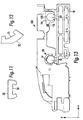
- Fig 13 shows a printer carriage 110 for sliding movement on sliding rods 12,113 attached to the main frame 18 of a printer.
- the carriage defines a front aperture 14 which is arranged to receive a bushing liner 20 in accordance with the present invention and a rear mounting 115 which is arranged to receive a conventional bushing liner 120.
- Forces F 1 and F 2 arise at the points of contact of bushing 20 and forces F 3 and F 4 arise at the points of contact of bushing 120.
- a preload spring 116 is provided between the carriage 110 and the rear bushing 120.
- the main purpose of this spring is to produce a horizontal force Fp in the x-direction which reduces the tendency of the carriage to turn around a vertical axis (i.e. the y-direction).
- the behaviour of the bearing is assisted by the definite location of the dimensionally-stable metallic parts of the liner 20 in aperture 14.
- the precise dimensioning of the metallic parts of the liner 20 and the accurate interference fit with aperture 14 makes the assembly reliable.
- the rigidity of the metallic parts resists large forces arising at the positions of contact, so there are no deformations and no adverse effects on print quality.
- the arrangement is very quiet.
- both static and dynamic forces need to be considered.
- static forces one needs to take into account the weight of the carriage and the printhead and any other components moving rigidly therewith, the forces applied by any ink supply tubes attached to the printhead, and the effect of preload spring 116.
- the force system is complicated by the various inertia forces. It is the purpose of the points of contact of the bushing liners to make the system as stable as possible at all times.
- dynamic forces to be taken into account are the frictional forces and the moments applied by the ink supply tubes and the frictional forces with relation to the slider rods (and directed perpendicular to the paper).
- the preload spring 116 can counter this tendency, excessive frictional forces can arise at the rear bushing.
- the force F 2 By making the angle between the points of contact of the bushing 20 different from 90° it is possible for the force F 2 to have a component in the horizontal direction (i.e. along the X-axis) to introduce the same stabilising effect as the preload spring, but without additional friction effects at the rear bushing.
- the angle between the points of contact is preferably within the range 100° to 165° and more preferably in the range 110° to 130°. This way of achieving stability is safer and more flexible than using spring 116 alone. Similar considerations apply in relation to carriages having a single slider rod, as in Fig.1.
- the size, location and number of the plastics inserts may be selected as desired.
- the plastics material may cover the entire inside surface of the metal material.
- each insert has two, three or four ribs.
- the length of one or more of the ribs may be less than the length "l" of the liner.
- Some or all of the ribs may extend in a circumferential direction. If desired, the ribs may be omitted completely, in which case the entirety of the slightly raised internal surface of the or each insert contacts the rod 12.
- the inserts 24, 25 may extend through the thickness of the liner 20 to any desired extent, from only a small proportion to substantially the entire thickness thereof.
- the external shape of the liner may be part-circular, polygonal or any suitable combination of curved and straight sections.
- the inserts may be pre-moulded and then placed in position rather than being injection moulded in situ.
- Stainless steel is the preferred material for body 21 in view of its high resistance to deformation.
- bronze or other metals may be used if desired.
- the printer carriage can be supported by one or more bushing liners 20 as required and the length "l" of each liner will be determined by the load to be carried. As shown in Fig.13, for certain printers and plotters a plurality of slider rods 12 are provided, each with one or more liners 20.
- An extra bushing housing may be provided between the printer carriage 10 and the or each liner 20.
- grooves may be provided directly in the walls of aperture 14 of the printer carriage, with the plastics inserts then being located in these grooves.
- the rear bushing 120 may be in accordance with the present invention instead of, or in addition to, the front bushing. Also, the direction of the forces arising may be arranged so that the preload spring 116 can be omitted.
Landscapes
- Engineering & Computer Science (AREA)
- General Engineering & Computer Science (AREA)
- Mechanical Engineering (AREA)
- Character Spaces And Line Spaces In Printers (AREA)
- Bearings For Parts Moving Linearly (AREA)
Claims (12)
- Dispositif d'imprimante/traceur comprenant un chariot (10 ; 110) monté pour un coulissement horizontal sur au moins une tige (12), le chariot se montant sur la ou chaque tige comprenant au moins un coussinet (20) ayant une section transversale en partie globalement annulaire et comprenant un matériau rigide, caractérisé en ce que le coussinet comprend, de plus, une ou plusieurs parties (24, 25) d'un matériau de lubrification, au moins une d'entre elles formant au moins une partie de la surface interne du coussinet, ledit matériau de lubrification étant différent dudit matériau rigide.
- Douille de coussinet (20) pour un chariot d'imprimante (10 ; 110) et possédant une section transversale en partie globalement annulaire, la douille de coussinet comprenant un matériau rigide, caractérisé en ce que le coussinet comprend, de plus, une ou plusieurs parties (24, 25) d'un matériau de lubrification, au moins une d'entre elles formant au moins une partie de la surtace interne du coussinet, ledit matériau de lubrification étant différent dudit matériau rigide.
- Douille de coussinet selon la revendication 2, dans laquelle le matériau rigide est un matériau métallique et le matériau de lubrification est une matière plastique.
- Douille de coussinet (20) selon la revendication 3, dans laquelle la surface interne du ou de chaque insert en matière plastique (24, 25) dépasse au-delà de la surface interne des parties (31, 32, 33) du matériau métallique.
- Douille de coussinet (20) selon la revendication 4, dans laquelle la surface interne du ou de chaque insert en matière plastique (24, 25) comprend une ou plusieurs nervures (60).
- Douille de coussinet (20) selon l'une quelconque des revendications 3 à 5, dans laquelle la matière plastique est appliquée au matériau métallique lors d'un processus de moulage par injection, le matériau métallique possédant des rainures (22, 23) qui sont conformées pour retenir la matière plastique après l'injection.
- Douille de coussinet (20) selon la revendication 6, dans laquelle les rainures (22, 23) comprennent des creux en forme de queue d'aronde (73, 74).
- Douille de coussinet (20) selon l'une quelconque des revendications 3 à 7, dans laquelle la surface externe de la douille de coussinet comprend une pluralité de sections plates et/ou incurvées disposées de façon asymétrique.
- Douille de coussinet (20) selon l'une quelconque des revendications 6 et 8, dans laquelle au moins un des inserts (24) est entièrement situé à l'intérieur d'une section plate de la douille de coussinet, dans laquelle les surfaces latérales (55) de la rainure respective (22) sont d'une forme concave.
- Douille de coussinet (20) selon l'une quelconque des revendications 2 à 4, dans laquelle les parties (24, 25) du matériau de lubrification comprennent une ou plusieurs nervures (60).
- Douille de coussinet (20) selon la revendication 10, dans laquelle les nervures (60) sont agencées selon des ensembles espacés selon la circonférence.
- Douille de coussinet (20) selon l'une quelconque des revendications précédentes, dans laquelle la surface interne du coussinet définit deux positions espacées selon la circonférence pour un contact avec la tige, les positions faisant un angle compris entre 100° et 165°.
Priority Applications (4)
| Application Number | Priority Date | Filing Date | Title |
|---|---|---|---|
| EP98120425A EP1013457B1 (fr) | 1998-10-29 | 1998-10-29 | Douille de chariot d'impression |
| ES98120425T ES2189067T3 (es) | 1998-10-29 | 1998-10-29 | Casquillo para carro de impresora. |
| DE69811247T DE69811247T2 (de) | 1998-10-29 | 1998-10-29 | Druckerschlittenbuchse |
| US09/429,436 US6575646B1 (en) | 1998-10-29 | 1999-10-28 | Printer carriage bushing |
Applications Claiming Priority (1)
| Application Number | Priority Date | Filing Date | Title |
|---|---|---|---|
| EP98120425A EP1013457B1 (fr) | 1998-10-29 | 1998-10-29 | Douille de chariot d'impression |
Publications (2)
| Publication Number | Publication Date |
|---|---|
| EP1013457A1 EP1013457A1 (fr) | 2000-06-28 |
| EP1013457B1 true EP1013457B1 (fr) | 2003-02-05 |
Family
ID=8232875
Family Applications (1)
| Application Number | Title | Priority Date | Filing Date |
|---|---|---|---|
| EP98120425A Expired - Lifetime EP1013457B1 (fr) | 1998-10-29 | 1998-10-29 | Douille de chariot d'impression |
Country Status (4)
| Country | Link |
|---|---|
| US (1) | US6575646B1 (fr) |
| EP (1) | EP1013457B1 (fr) |
| DE (1) | DE69811247T2 (fr) |
| ES (1) | ES2189067T3 (fr) |
Families Citing this family (11)
| Publication number | Priority date | Publication date | Assignee | Title |
|---|---|---|---|---|
| JP2000114246A (ja) * | 1998-08-07 | 2000-04-21 | Ulvac Seimaku Kk | ドライエッチング方法および装置、フォトマスクおよびその作製方法、ならびに半導体回路およびその製作方法 |
| DE60021073T2 (de) * | 2000-08-24 | 2006-05-18 | Hewlett-Packard Development Company, L.P., Houston | Tragprofil für Transferwagen |
| JP4497702B2 (ja) | 2000-10-31 | 2010-07-07 | キヤノン株式会社 | 記録装置 |
| KR100385992B1 (ko) | 2001-02-13 | 2003-06-02 | 삼성전자주식회사 | 왕복식 프린터헤드의 캐리지 어셈블리 |
| NL1021851C2 (nl) | 2002-11-06 | 2004-05-07 | Oce Tech Bv | Geleideinrichting voor een inkjet printer. |
| JP3858998B2 (ja) * | 2003-04-25 | 2006-12-20 | ブラザー工業株式会社 | 画像形成装置 |
| US7192116B2 (en) * | 2003-11-26 | 2007-03-20 | Fuji Xerox Co., Ltd. | Systems and methods for dissipating heat from a fluid ejector carriage |
| DE202004016094U1 (de) * | 2004-10-15 | 2006-02-23 | Igus Gmbh | Gleitlager und Linearführung |
| US10514061B2 (en) * | 2018-05-23 | 2019-12-24 | John Wun-Chang Shih | Linear moving bearing |
| DE202022102167U1 (de) | 2022-04-22 | 2023-08-04 | Igus Gmbh | Lineargleitlager |
| CN219096314U (zh) * | 2022-10-26 | 2023-05-30 | 深圳市安克智造科技有限公司 | 打印设备 |
Family Cites Families (9)
| Publication number | Priority date | Publication date | Assignee | Title |
|---|---|---|---|---|
| US4756630A (en) * | 1982-05-07 | 1988-07-12 | Teeslink John W | Toolholder guide |
| US4468144A (en) * | 1982-06-09 | 1984-08-28 | Contitronix, Inc. | Detachable carriage assembly for printer |
| SE467754B (sv) * | 1990-12-27 | 1992-09-07 | Precisions Produkter Ab | Linjaerstyrningssystem |
| US5348404A (en) * | 1992-10-23 | 1994-09-20 | Hewlett-Packard Company | Split bushing mounting of a printer carriage with pre-load |
| US5332321A (en) * | 1992-10-23 | 1994-07-26 | Hewlett-Packard Corporation | Two line contact bushing mounting of a plotter carriage with pre-load |
| US5346320A (en) * | 1992-10-23 | 1994-09-13 | Hewlett-Packard Company | Printer carriage bushing |
| DE4303177A1 (de) * | 1993-02-04 | 1994-08-11 | Freudenberg Carl Fa | Führungshülse |
| US5366305A (en) * | 1993-06-09 | 1994-11-22 | Hewlett-Packard Company | Two-line contact carriage bearing subsystem |
| DE19600870C1 (de) * | 1996-01-12 | 1997-08-14 | Freudenberg Carl Fa | Stangenführung |
-
1998
- 1998-10-29 EP EP98120425A patent/EP1013457B1/fr not_active Expired - Lifetime
- 1998-10-29 ES ES98120425T patent/ES2189067T3/es not_active Expired - Lifetime
- 1998-10-29 DE DE69811247T patent/DE69811247T2/de not_active Expired - Fee Related
-
1999
- 1999-10-28 US US09/429,436 patent/US6575646B1/en not_active Expired - Fee Related
Also Published As
| Publication number | Publication date |
|---|---|
| US6575646B1 (en) | 2003-06-10 |
| DE69811247D1 (de) | 2003-03-13 |
| EP1013457A1 (fr) | 2000-06-28 |
| ES2189067T3 (es) | 2003-07-01 |
| DE69811247T2 (de) | 2003-12-04 |
Similar Documents
| Publication | Publication Date | Title |
|---|---|---|
| US6575646B1 (en) | Printer carriage bushing | |
| US6617733B1 (en) | Magnetic bearing apparatus and vacuum pump having magnetic bearing apparatus | |
| EP0367119A2 (fr) | Mécanisme de direction à crémaillère | |
| JP2875781B2 (ja) | すきまゼロ軸受 | |
| EP0622759B1 (fr) | Montage d'un manchon ayant deux contacts en ligne pour un chariot de traceur avec préchargement | |
| GB2124715A (en) | Rectilinear motion rolling bearing with adjustable preload | |
| JPH0719246A (ja) | 滑り軸受サブシステム | |
| US5820269A (en) | Roller-type linear guide apparatus | |
| US6170989B1 (en) | Modular support structure for hydrodynamic bearing | |
| US20050041896A1 (en) | Guide unit | |
| EP1231069B1 (fr) | Assemblage de chariot d'imprimante avec tête d'impression déplaçable | |
| US6371648B1 (en) | Linear guide device | |
| JPH07190052A (ja) | 合成樹脂製弾性軸受体 | |
| US4461518A (en) | Sliding roller bearing | |
| US5348404A (en) | Split bushing mounting of a printer carriage with pre-load | |
| US5346320A (en) | Printer carriage bushing | |
| JP2934871B1 (ja) | 軸受部材 | |
| US12381445B2 (en) | Rotor bearing arrangement for electric motor | |
| EP1881214A1 (fr) | Dispositif a guide lineaire | |
| JP3264099B2 (ja) | ラックピニオン式ステアリング装置 | |
| CN118030780A (zh) | 一种座椅驱动器及其设计方法、组装方法 | |
| CN119731443A (zh) | 线性滑动轴承 | |
| JP5015693B2 (ja) | 揺動軸受 | |
| JPH085899Y2 (ja) | ラックピニオン式ステアリング装置 | |
| JP3624301B2 (ja) | ラックピニオン式舵取装置 |
Legal Events
| Date | Code | Title | Description |
|---|---|---|---|
| PUAI | Public reference made under article 153(3) epc to a published international application that has entered the european phase |
Free format text: ORIGINAL CODE: 0009012 |
|
| AK | Designated contracting states |
Kind code of ref document: A1 Designated state(s): DE ES GB |
|
| AX | Request for extension of the european patent |
Free format text: AL;LT;LV;MK;RO;SI |
|
| 17P | Request for examination filed |
Effective date: 20001222 |
|
| AKX | Designation fees paid |
Free format text: DE ES GB |
|
| 17Q | First examination report despatched |
Effective date: 20010309 |
|
| RAP1 | Party data changed (applicant data changed or rights of an application transferred) |
Owner name: HEWLETT-PACKARD COMPANY, A DELAWARE CORPORATION |
|
| GRAG | Despatch of communication of intention to grant |
Free format text: ORIGINAL CODE: EPIDOS AGRA |
|
| GRAG | Despatch of communication of intention to grant |
Free format text: ORIGINAL CODE: EPIDOS AGRA |
|
| GRAH | Despatch of communication of intention to grant a patent |
Free format text: ORIGINAL CODE: EPIDOS IGRA |
|
| GRAH | Despatch of communication of intention to grant a patent |
Free format text: ORIGINAL CODE: EPIDOS IGRA |
|
| GRAA | (expected) grant |
Free format text: ORIGINAL CODE: 0009210 |
|
| AK | Designated contracting states |
Designated state(s): DE ES GB |
|
| REG | Reference to a national code |
Ref country code: GB Ref legal event code: FG4D |
|
| REF | Corresponds to: |
Ref document number: 69811247 Country of ref document: DE Date of ref document: 20030313 Kind code of ref document: P |
|
| REG | Reference to a national code |
Ref country code: ES Ref legal event code: FG2A Ref document number: 2189067 Country of ref document: ES Kind code of ref document: T3 |
|
| PLBE | No opposition filed within time limit |
Free format text: ORIGINAL CODE: 0009261 |
|
| STAA | Information on the status of an ep patent application or granted ep patent |
Free format text: STATUS: NO OPPOSITION FILED WITHIN TIME LIMIT |
|
| 26N | No opposition filed |
Effective date: 20031106 |
|
| PGFP | Annual fee paid to national office [announced via postgrant information from national office to epo] |
Ref country code: ES Payment date: 20071026 Year of fee payment: 10 Ref country code: DE Payment date: 20071130 Year of fee payment: 10 |
|
| PG25 | Lapsed in a contracting state [announced via postgrant information from national office to epo] |
Ref country code: DE Free format text: LAPSE BECAUSE OF NON-PAYMENT OF DUE FEES Effective date: 20090501 |
|
| REG | Reference to a national code |
Ref country code: ES Ref legal event code: FD2A Effective date: 20081030 |
|
| PG25 | Lapsed in a contracting state [announced via postgrant information from national office to epo] |
Ref country code: ES Free format text: LAPSE BECAUSE OF NON-PAYMENT OF DUE FEES Effective date: 20081030 |
|
| REG | Reference to a national code |
Ref country code: GB Ref legal event code: 732E Free format text: REGISTERED BETWEEN 20120329 AND 20120404 |
|
| PGFP | Annual fee paid to national office [announced via postgrant information from national office to epo] |
Ref country code: GB Payment date: 20130923 Year of fee payment: 16 |
|
| GBPC | Gb: european patent ceased through non-payment of renewal fee |
Effective date: 20141029 |
|
| PG25 | Lapsed in a contracting state [announced via postgrant information from national office to epo] |
Ref country code: GB Free format text: LAPSE BECAUSE OF NON-PAYMENT OF DUE FEES Effective date: 20141029 |