EP1013483A2 - Dispositif de transmission d'informations issues d'une roue de véhicule et dispositif de détection d'anomalie pour un pneumatique - Google Patents
Dispositif de transmission d'informations issues d'une roue de véhicule et dispositif de détection d'anomalie pour un pneumatique Download PDFInfo
- Publication number
- EP1013483A2 EP1013483A2 EP99125661A EP99125661A EP1013483A2 EP 1013483 A2 EP1013483 A2 EP 1013483A2 EP 99125661 A EP99125661 A EP 99125661A EP 99125661 A EP99125661 A EP 99125661A EP 1013483 A2 EP1013483 A2 EP 1013483A2
- Authority
- EP
- European Patent Office
- Prior art keywords
- wheel
- information
- wheel information
- air pressure
- state
- Prior art date
- Legal status (The legal status is an assumption and is not a legal conclusion. Google has not performed a legal analysis and makes no representation as to the accuracy of the status listed.)
- Withdrawn
Links
- 230000005856 abnormality Effects 0.000 title claims description 38
- 230000005540 biological transmission Effects 0.000 claims description 102
- 230000009467 reduction Effects 0.000 claims description 88
- 230000002159 abnormal effect Effects 0.000 claims description 58
- 230000003213 activating effect Effects 0.000 claims description 4
- 230000007423 decrease Effects 0.000 description 19
- 230000008859 change Effects 0.000 description 17
- 230000005684 electric field Effects 0.000 description 6
- 230000001186 cumulative effect Effects 0.000 description 4
- 238000010586 diagram Methods 0.000 description 4
- 238000001514 detection method Methods 0.000 description 2
- 101150004367 Il4i1 gene Proteins 0.000 description 1
- 230000001133 acceleration Effects 0.000 description 1
- 230000006870 function Effects 0.000 description 1
- 230000004048 modification Effects 0.000 description 1
- 238000012986 modification Methods 0.000 description 1
- 230000000737 periodic effect Effects 0.000 description 1
- 230000004044 response Effects 0.000 description 1
- 230000000630 rising effect Effects 0.000 description 1
Images





Classifications
-
- B—PERFORMING OPERATIONS; TRANSPORTING
- B60—VEHICLES IN GENERAL
- B60C—VEHICLE TYRES; TYRE INFLATION; TYRE CHANGING; CONNECTING VALVES TO INFLATABLE ELASTIC BODIES IN GENERAL; DEVICES OR ARRANGEMENTS RELATED TO TYRES
- B60C23/00—Devices for measuring, signalling, controlling, or distributing tyre pressure or temperature, specially adapted for mounting on vehicles; Arrangement of tyre inflating devices on vehicles, e.g. of pumps or of tanks; Tyre cooling arrangements
- B60C23/02—Signalling devices actuated by tyre pressure
- B60C23/04—Signalling devices actuated by tyre pressure mounted on the wheel or tyre
- B60C23/0408—Signalling devices actuated by tyre pressure mounted on the wheel or tyre transmitting the signals by non-mechanical means from the wheel or tyre to a vehicle body mounted receiver
-
- B—PERFORMING OPERATIONS; TRANSPORTING
- B60—VEHICLES IN GENERAL
- B60C—VEHICLE TYRES; TYRE INFLATION; TYRE CHANGING; CONNECTING VALVES TO INFLATABLE ELASTIC BODIES IN GENERAL; DEVICES OR ARRANGEMENTS RELATED TO TYRES
- B60C23/00—Devices for measuring, signalling, controlling, or distributing tyre pressure or temperature, specially adapted for mounting on vehicles; Arrangement of tyre inflating devices on vehicles, e.g. of pumps or of tanks; Tyre cooling arrangements
- B60C23/02—Signalling devices actuated by tyre pressure
- B60C23/04—Signalling devices actuated by tyre pressure mounted on the wheel or tyre
- B60C23/0408—Signalling devices actuated by tyre pressure mounted on the wheel or tyre transmitting the signals by non-mechanical means from the wheel or tyre to a vehicle body mounted receiver
- B60C23/0422—Signalling devices actuated by tyre pressure mounted on the wheel or tyre transmitting the signals by non-mechanical means from the wheel or tyre to a vehicle body mounted receiver characterised by the type of signal transmission means
- B60C23/0433—Radio signals
- B60C23/0447—Wheel or tyre mounted circuits
- B60C23/0455—Transmission control of wireless signals
- B60C23/0462—Structure of transmission protocol
-
- B—PERFORMING OPERATIONS; TRANSPORTING
- B60—VEHICLES IN GENERAL
- B60C—VEHICLE TYRES; TYRE INFLATION; TYRE CHANGING; CONNECTING VALVES TO INFLATABLE ELASTIC BODIES IN GENERAL; DEVICES OR ARRANGEMENTS RELATED TO TYRES
- B60C23/00—Devices for measuring, signalling, controlling, or distributing tyre pressure or temperature, specially adapted for mounting on vehicles; Arrangement of tyre inflating devices on vehicles, e.g. of pumps or of tanks; Tyre cooling arrangements
- B60C23/02—Signalling devices actuated by tyre pressure
- B60C23/04—Signalling devices actuated by tyre pressure mounted on the wheel or tyre
- B60C23/0408—Signalling devices actuated by tyre pressure mounted on the wheel or tyre transmitting the signals by non-mechanical means from the wheel or tyre to a vehicle body mounted receiver
- B60C23/0474—Measurement control, e.g. setting measurement rate or calibrating of sensors; Further processing of measured values, e.g. filtering, compensating or slope monitoring
Definitions
- the present invention relates to a vehicle wheel information supply device for supplying wheel information relating to a state of a wheel of a vehicle, which device includes a transmitter disposed on the wheel and a receiver disposed on the body of the vehicle.
- the present invention is also concerned with a wheel tire abnormality indicating device which includes such a wheel information supply device, and an indicator operated in response to an output of the vehicle wheel information supply device, to indicate an abnormality of a tire of the vehicle wheel.
- JP-U-5-13802 discloses an example of such kind of vehicle wheel information supply device in the form of a tire air pressure information supply device adapted to supply tire air pressure information indicating whether an air pressure in a tire of a wheel of an automotive vehicle is normal or not.
- This tire air pressure information supply device includes an air pressure detector disposed on the vehicle wheel to detect the air pressure of the wheel tire, an air pressure information transmitter also disposed on the vehicle wheel to transmit the tire air pressure information, and an air pressure information receiver disposed on the vehicle body to receive the tire air pressure information transmitted by the air pressure information transmitter.
- the air pressure information transmitter Based on an output of the air pressure detector, the air pressure information transmitter intermittently transmits a pulse signal of a predetermined pattern when the output indicates that the tire air pressure is normal, and continuously transmits a pulse signal of another predetermined pattern when the output indicates that the tire air pressure is abnormal.
- the air pressure information transmitter in the tire air pressure information supply device described above is adapted to transmit a pulse signal in different patterns where the tire air pressure is normal and where it is abnormal.
- the air pressure information receiver disposed on the vehicle body includes a receiving portion including an antenna.
- the air pressure information transmitter disposed on the vehicle wheel is rotated with the vehicle wheel, so that a distance between this transmitter and the receiving portion of the air pressure information receiver periodically changes, causing a periodic change in the amplitude or intensity of the signal received by the receiver.
- the signal-to-noise ratio (SN ratio) is relatively low, and the receiver may not receive the signal whose intensity is high enough to correctly represent the air pressure information.
- the time period required for the transmitter to transmit the air pressure information is relatively long, the probability of incorrect reception of the information is lower due to an influence of the noise on a part of the information than where the time period is relatively short.
- the probability of correct reception of the entire information by the receiver is lowered with an increase in the time period of the transmission.
- the time period of the transmission where the tire air pressure is normal is the same as that where the tire air pressure is abnormal.
- the reception ratio is lower when the rotating speed of the vehicle wheel is relatively high than when the rotating speed is relatively low, provided the time period of the transmission and the noise level are constant. This is because the ratio of the time period required to transmit a series of the air pressure information to the time period required for one revolution of the wheel increases with an increase in the rotating speed of the wheel.
- Another object of the invention is to provide a vehicle wheel tire abnormality indicating device which includes such a vehicle wheel information supply device.
- a wheel state indicating device in the form of a wheel tire abnormality indicating device including a wheel information supply device constructed according to one embodiment of this invention.
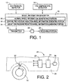
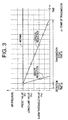
- FIGs. 1 and 2 there are disposed on each of front right and left and rear right and left wheels 10 of an automotive vehicle, an air pressure detector 12 for detecting an air pressure in a tire of the corresponding wheel 10, a tire temperature detector 14 for detecting a temperature of the tire, a wheel information generator 16 for generating wheel information relating to a state of the wheel 10, and a transmitter 18 for transmitting the wheel information generated by the wheel information generator 16.
- the air pressure detector 12 is located at a portion of the wheel 10 at which a valve of the tire is located.
- the air pressure detector 12 generates an output signal while the air pressure of the wheel tire is higher than a given level, namely, while the tire air pressure is detectable.
- the four antennas 22 are located at respective positions at which the wheel information can be received from the respective transmitters 18 disposed on the respective four wheels 10.
- the receiving portion 23 is adapted to receive, through the antennas 22, the wheel information transmitted by the transmitters 18.
- the receiving portion 23 is further adapted to modulate and amplify the wheel information, before the wheel information is fed to the controller 24, to which is connected an indicator 26.
- the controller 24 controls the indicator 26 to provide an indication of the state of each wheel 10, based on the received wheel information, so that the operator of the vehicle is informed of the state of each wheel 10.
- the indicator 26 is provided in a driver's compartment of the vehicle. It will be understood that the antennas 22, the receiving portion 23 and the controller 24 cooperate to constitute a receiver 28.
- the wheel information generator 16 is principally constituted by a computer incorporating a central processing unit (CPU), a random-access memory (RAM), a read-only memory (ROM), an input portion and an output portion. To the input portion of the generator 16, there are connected the air pressure detector 12 and the tire temperature detector 14. To the output portion of the device 16, there is connected the transmitter 18.
- the ROM stores various programs such as a program for executing a wheel information generating portion selecting routine illustrated in the flow chart of Fig. 5, and a program for executing a normal wheel information generating routine illustrated in the flow chart of Fig. 6.
- the wheel information generator 16 includes a normal wheel information generating portion 30, a gradual tire pressure reduction wheel information generating portion 32, and an abrupt tire pressure reduction wheel information generating portion 34, as shown in Fig.
- wheel information generating portion selecting routine of Fig. 5 being executed, one of the three wheel information generating portions 30, 32, 34 is selected, so that the wheel information is generated by the selected wheel information generating portion.
- the generated wheel information is transmitted by the transmitter 18 to the receiving portion 23 of the receiver 28.
- Each of the normal wheel information generating portion 30, gradual tire pressure reduction wheel information generating portion 32 and abrupt tire pressure reduction wheel information generating portion 34 is constituted by a portion of the computer of the wheel information generator 16 which is assigned to store and implement a whole or a part of a program for generating a series of wheel information based on the detected tire air pressure, etc.
- those generating portions 30, 32, 34 may be constituted by respective exclusive computers or respective hardware circuits.
- the controller 24 is also principally constituted by a computer incorporating a CPU, a RAM, a ROM, an input portion and an output portion.
- the ROM stores programs such as a program for executing an identification data registering routine illustrated in the flow chart of Fig. 7. With the identification data registering routine of Fig. 7 being executed, identification data received from the transmitter 18 are registered in the receiver 28.
- the wheel information generator 16 selects and activates one of the three wheel information generating portions 30, 32, 34.
- the wheel information generated by the normal wheel information generating portion 30 has the largest volume, and the wheel information generated by the abrupt tire pressure reduction wheel information generating portion 34 has the smallest volume. It is also noted that the frequency of generation of the wheel information by the normal wheel information generating portion 30 is the lowest, while the frequency of generation of the wheel information by the abrupt tire pressure reduction wheel information generating portion 34 is the highest.
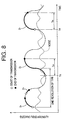
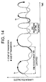
- the intensity of an electric field between these transmitter and receiver changes with a change in the distance, as indicated in the graph of Fig. 8. That is, the intensity of the information signal received by the receiver changes as indicated in Fig. 8.
- the information transmitted from the transmitter can be received by the receiver when the intensity of the electric field is sufficiently high.
- the intensity of the electric field is low, the transmitted information may not be received by the receiver, due to an influence of a noise. While the intensity of the electric field is lower than that of the noise indicated by broken line in Fig. 8, the transmitted wheel information cannot be received.
- a series of information D 1 is transmitted for a time period of T D 1 , as indicated in Fig. 8, the information D 1 cannot be received if the transmission of the information starts at a point of time TA, but can be received if the transmission starts at a point of time TA'.
- the probability of correct reception of the transmitted information is referred to as a reception ratio.
- the reception ratio increases with a decrease in the noise level and a decrease in the volume of the information transmitted (a decrease in the time period required to transmit the information).
- the reception ratio is relatively high when the information volume is relatively small as indicated at D 2 and D 3 in Fig. 8, the number of items represented by the information is relatively small. Therefore, the volume of the information to be transmitted must be determined by taking into account both the reception ratio and the desired number of items represented by the information.
- the apparent reception ratio increases with an increase in the number of receptions (transmissions) of the wheel information, as indicated in Fig. 9.
- the apparent reception ratio can be increased by increasing the number of receptions of the wheel information.
- the reception ratio is 100% (99.999% or higher) with one reception
- the apparent reception ratio is 100%.
- the reception ratio is 99% with one reception
- the apparent reception ratio can be increased to 100% with three receptions.
- the reception ratio is 80% with one reception, the apparent reception ratio can be increased to 100% with eight receptions.
- the apparent reception ratio increases with a decrease in the volume of the wheel information (required transmission or reception time) and an increase in the number of receptions (transmissions).
- the present embodiment is arranged to reduce the volume of the wheel information and increase the frequency of transmission of the wheel information by the transmitter 18 (number of transmissions of the wheel information), where a need for correct reception of the wheel information by the receiver 28 is relatively high.
- the tire air pressure is detected intermittently at a time interval of ⁇ t, namely, with a cycle time of ⁇ t.
- the wheel information generator 16 determines that the tire air pressure is normal, and selects and activates the normal wheel information generating portion 30 to generate NORMAL wheel information 50 indicated in Fig. 4.
- the NORMAL wheel information 50 consists of a header in the form of SYNCHRONIZATION data 51, TRAILER data 52, IDENTIFICATION data 53, AIR PRESSURE data 54, TIRE TEMPERATURE data 55, TRANSMISSION STATE data 56 and CHECK SUM data 57.
- the AIR PRESSURE data 54 represent the tire air pressure of the wheel 10
- the TIRE TEMPERATURE data 55 represent the temperature of the tire.
- the TRANSMISSION STATE data 56 consist of TRANSMISSION STATE data 1 and TRANSMISSION STATE data 2.
- the NORMAL wheel information 50 is generated by the normal wheel information generating portion 30, with the cycle time of ⁇ T, which is considerably longer than the cycle time ⁇ t with which the tire air pressure is detected. To generate the NORMAL wheel information 50, the outputs of the air pressure detector 12 and the tire temperature detector 14 are read into the wheel information generator 16.
- the AIR PRESSURE data 54 and the TIRE TEMPERATURE data 55 serve as primary information
- the SYNCHRONIZATION data 51, TRAILER data 52, IDENTIFICATION data 53, TRANSMISSION STATE data 56 and CHECK SUM data 57 serve as ancillary data.
- the SYNCHRONIZATION data 51 and the TRAILER data 52 of the ancillary data serve as header/trailer data.
- the TRAILER data 52 indicate the end of the NORMAL wheel information 50, and represents a predetermined total volume of the NORMAL wheel information 50, which is different from the total volumes of ABRUPT TIRE PRESSURE REDUCTION wheel information 60 and GRADUAL TIRE PRESSURE REDUCTION wheel information 70 which are generated by the abrupt tire pressure reduction wheel information generating portion 34 and the gradual tire pressure reduction wheel information generating portion 32, respectively.
- the NORMAL wheel information 50, ABRUPT TIRE PRESSURE REDUCTION wheel information 60 and GRADUAL TIRE PRESSURE REDUCTION wheel information 70 have respective different predetermined total volumes, as described below.
- the total volume of the wheel information indicates whether the wheel 10 is in the normal state, or in the state of abrupt or gradual reduction of its tire air pressure.
- the data 51-57 are indicated as [SYNC] [00] [ID1][ID2][ID3][ID4] [AIR PRESSURE] [TIRE TEMP] [TRANS STATE 1][TRANS STATE 2] [CHECK SUM].
- the data [00] constitute the TRAILER data 52, and the data [ID1][ID2][ID3][ID4] constitute the IDENTIFICATION data 53, while the data [TRANS STATE 1][TRANS STATE 2] constitute the TRANSMISSION STATE data 56.
- Each of [SYNC], [ID1], [ID2], [ID3], [ID4], [AIR PRESSURE], [TIRE TEMP), [TRANS STATE 1], [TRANS STATE 2] and [CHECK SUM] is a one byte volume. Since the data [00] (TRAILER data 52) is 0.5 byte, the total volume of the NORMAL wheel information 50 is 10.5 bytes. In the ABRUPT TIRE PRESSURE REDUCTION wheel information 60 and the GRADUAL TIRE PRESSURE REDUCTION wheel information 70, TRAILER data 62 and TRAILER data 72 are [01] and [10], respectively.
- the TRAILER data are [00]
- the TRAILER data 52, 62, 72 are considered to be air pressure information indicative of the tire air pressure.
- the TRAILER data 52, 62, 72 representing the total volume of the wheel information 50, 60, 70 may be considered to be transmission volume information indicative of the total volume of the wheel information transmitted.
- the TRAILER data 52, 62, 72 serve as the air pressure information (which can be considered as the primary information), transmission volume information, and ancillary information (header/trailer information).
- the IDENTIFICATION data 53 are provided to check if the wheel information transmitted from the transmitter 18 disposed on each of the four wheels 10 is received by the corresponding one of the four receiving portions 23 of the receiver 28 disposed at the respective positions on the vehicle body 20, which positions correspond to the respective four wheels 10.
- the data sets [ID1], [ID2], [ID3] and [ID4] of the IDENTIFICATION data 53 correspond to the respective four receiving portions 23, that is, respective four wheels 10.
- the data sets [ID1], [ID2], [ID3] and [ID4] are sent to the receiver 28, so as to be registered in the receiver 28, in relation to the respective receiving portions 23 or wheels 10.
- the IDENTIFICATION data 53 contained in the wheel information are compared with the data sets registered in the receiver 28, to confirm that the transmitter 18 from which the wheel information is transmitted corresponds to the appropriate receiving portion 23 or wheel 10.
- the registration of the IDENTIFICATION data is automatically effected when the air pressure in the tire of the wheel 10 is raised to a level detectable by the air pressure detector 12 upon attachment of each wheel 10 to the vehicle body 20.
- the transmitter 18 for the wheel 10 in question transmits to the receiver 28 the IDENTIFICATION data together with a REGISTRATION MODE signal.
- the receiver 28 is held in a RECEPTION STANDBY mode in which wheel information transmitted by the transmitter 18 is receivable.
- the receiver 28 To register the IDENTIFICATION data, the receiver 28 must be brought into a REGISTRATION mode. This REGISTRATION mode is established when the receiver 28 has received the REGISTRATION MODE signal from the transmitter 18.
- the IDENTIFICATION data transmitted from the transmitter 18 can be registered in the receiver 28.
- This arrangement does not require the receiver 28 to have an exclusive operator-controlled switch for changing the mode from the RECEPTION STANDBY mode to the REGISTRATION mode.
- the IDENTIFICATION data follow the REGISTRATION MODE signal, without any information interlaced therebetween, so that the IDENTIFICATION data received from the transmitter 18 can be correctly registered in the receiver 28 with high stability.
- the IDENTIFICATION data are registered in the receiver 28, with the controller 24 executing the identification data registering routine illustrated in the flow chart of Fig. 7.
- This routine is initiated with step S1 to determine whether any information is received. If an affirmative decision (YES) is obtained in step S1, the control flow goes to step S2 to determine whether the information received is the wheel information (tire air pressure, etc.) or other information that is to be normally processed. If a negative decision (NO) is obtained in step S2, the control flow goes to step S3 to determine whether the information received is the REGISTRATION MODE signal and the IDENTIFICATION data.
- step S3 If an affirmative decision (YES) is obtained in step S3, the control flow goes to step S4 in which the REGISTRATION mode is established, and the IDENTIFICATION data are registered in the controller 24. Then, the control flow goes to step S5 in which the receiver 28 is returned to the RECEPTION STANDBY mode.
- the IDENTIFICATION data registered for all wheels 10 the wheel information received by the receiver 28 is related to the corresponding one of the receiving portions 23 (wheels 10).
- the IDENTIFICATION data 53 to be registered include [ID1], [ID2], [ID3] and [ID4] indicated above, and [ID4] and [ID5] which will be described.
- step S1 If the information received in step S1 is neither the information that is to be normally processed, nor a combination of the REGISTRATION MODE signal and the IDENTIFICATION data, a negative decision (NO) is obtained in steps S2 and S3, and the control flow goes to step S7 in which the received information is processed in a manner corresponding to the kind of the information. If an affirmative decision (YES) is obtained in step S2, the control flow goes to step S6 in which the information received is processed in the normal manner. Step S6 and S7 are also followed by the above-indicated step S5 so that the receiver 28 is returned to the RECEPTION STANDBY mode.
- the TRANSMISSION STATE data 56 indicate the state of transmission of the NORMAL wheel information 50, and include data indicating whether the transmitter 18 in question is normal, and data indicative of the residual amount of electric energy left (voltage) in a battery used in the transmitter 18.
- the SYNCHRONIZATION data 51 [SYNC]) are provided for synchronization of the transmitter 18 with the receiver 28.
- the detected tire air pressure of the wheel 10 When the detected tire air pressure of the wheel 10 is normal, a need of transmitting the NORMAL wheel information 50 so as to assure correct reception thereof is relatively small, and the reception ratio of the NORMAL wheel information 50 need not be so high. In view of this, the total volume of the NORMAL wheel information 50 may be relatively large, and the frequency of transmission of this information 50 need not be so high.
- the wheel information generator 16 selects and activates the abrupt tire pressure reduction wheel information generating portion 34, and this generating portion 34 generates the ABRUPT TIRE PRESSURE REDUCTION wheel information 60, which consists of SYNCHRONIZATION data 62, TRAILER data 62, IDENTIFICATION data 63, AIR PRESSURE data 64 and CHECK SUM data 65, as indicated in Fig. 4.
- the ABRUPT TIRE PRESSURE REDUCTION wheel information 60 does not include TIRE TEMPERATURE data and TRANSMISSION STATE data, and the total volume of the wheel information 60 is 7.5 bytes.
- the AIR PRESSURE data 64 serve as the primary information
- the SYNCHRONIZATION data 61, TRAILER data 62, IDENTIFICATION data 63 and CHECK SUM data 65 serve as the ancillary data.
- the SYNCHRONIZATION data 61 and the TRAILER data 62 serve as the header/trailer information.
- the TRAILER data 62 in the wheel information 60 is [01], which indicates that the tire air pressure is lower than the preset value Ps and is abruptly lowered.
- the ABRUPT TIRE PRESSURE REDUCTION wheel information 60 is generated and transmitted with the cycle time of ⁇ t, which is the cycle time of detection of the tire air pressure. As indicated above, the volume of the wheel information 60 is made relatively small, and the frequency of transmission of this wheel information 60 is made relatively high, in order to increase the reception ratio on the side of the receiver 28.
- the generator 16 selects and activates the gradual tire pressure reduction wheel information generating portion 32, and this generating portion 32 generates the GRADUAL TIRE PRESSURE REDUCTION wheel information 70, which consists of SYNCHRONIZATION data 71, TRAILER data 72, IDENTIFICATION data 73, AIR PRESSURE data 74, TIRE TEMPERATURE data 75 and CHECK SUM data 76.
- the GRADUAL TIRE PRESSURE REDUCTION wheel information 70 does not include TRANSMISSION STATE data, and the total volume of the wheel information 70 is 8.5 bytes, which is intermediate between the total volumes of the NORMAL wheel information 50 and the ABRUPT TIRE PRESSURE REDUCTION wheel information 60.
- the TRAILER data 72 in this wheel information 70 is [10], which indicates that the tire air pressure is lower than the preset value Ps and is gradually lowered at a rate lower than the predetermined threshold.
- the wheel information 70 including the AIR PRESSURE data 74 and TIRE TEMPERATURE data 75 is generated and transmitted with a cycle time of 2 x ⁇ t. As indicated above, the total volume of the wheel information 70 is smaller than that of the NORMAL wheel information 50, and the frequency of transmission of the wheel information 70 is higher than that of the wheel information 50, so that the reception ratio of the wheel information 70 is made higher.
- the wheel information received by the receiving portion 23 is supplied to the controller 24, and the indicator 26 is controlled by the controller 24, depending upon the content of the wheel information received.
- the indicator 26 is controlled to indicate both the tire air pressure and the tire temperature.
- the indicator 26 is controlled to indicate only the tire air pressure and activate an alarm light provided thereon, in order to inform the vehicle operator or driver of an abrupt reduction of the tire air pressure of the wheel 10 corresponding to the transmitter 18 from which the wheel information 70 is received.
- step S21 to read in the detected tire air pressure of each wheel 10.
- step S21 is followed by step S22 to determine whether the detected tire air pressure is lower than the preset value Ps. If a negative decision (NO) is obtained in step S22, the control flow goes to step S23 in which the normal wheel information generating portion 30 is selected.
- the normal wheel information generating portion 30 generates the NORMAL wheel information 50 with the cycle time ⁇ T, which is considerably longer than the cycle time ⁇ t.
- the generated NORMAL wheel information 50 is sent to the appropriate transmitter 18, which transmits the wheel information 50 to the receiving portion 23 of the receiver 28.
- step S23 When step S23 is initially implemented to select the normal wheel information generating portion 30, a normal wheel information generating routine is started by the wheel information generator 16, as illustrated in the flow chart of Fig. 6, to generate the NORMAL wheel information 50 with the cycle time ⁇ T, while the wheel information generating portion selecting routine of Fig. 5 is repeatedly implemented with the cycle time of ⁇ t. That is, each time step S23 is implemented, a counter Co is incremented, and the NORMAL wheel information 50 is generated by the selected generating portion 30 when the content "n" of the counter Co has been increased to a predetermined value "n 0 " which corresponds to the cycle time ⁇ T.
- step S51 The normal wheel information generating routine of Fig. 6 is initiated with step S51 in which the content "n" of a counter Co is incremented to "n+1". Then, step S52 is implemented to determine whether the content "n" is equal to or larger than the predetermined value "n 0 ". If a negative decision (NO) is obtained in step S52, one cycle of execution of the routine of Fig. 6 is terminated, and the NORMAL wheel information 50 is not generated by the generating portion 30. If an affirmative decision (YES) is obtained in step S52, the control flow goes to step S53 in which the normal wheel information generating portion 30 generates the NORMAL wheel information 50. Step S53 is followed by step S54 to reset the counter Co.
- step S22 If the detected tire air pressure is lower than the present value Ps, an affirmative decision (YES) is obtained in step S22 of the routine of Fig. 5, and the control flow goes to step S34 in which the rate of reduction of the tire air pressure is calculated. Step S22 is followed by step S25 to determine whether the calculated rate of reduction of the tire air pressure is higher than the predetermined threshold or not. If an affirmative decision (YES) is obtained in step S25, the control flow goes to step S26 in which the abrupt tire pressure reduction wheel information generating portion 34 is selected and activated to generate the ABRUPT TIRE PRESSURE REDUCTION wheel information 60, so that the generated wheel information 60 is transmitted to the receiver 28. Thus, the wheel information 60 is generated each time step S26 is implemented, namely, with the cycle time of ⁇ t.
- step S25 If the rate of reduction of the detected tire air pressure is not higher than the threshold, a negative decision (NO) is obtained in step S25, and the control flow goes to step S27 in which the gradual tire pressure reduction wheel information generating portion 32 is selected and activated, to generate the GRADUAL TIRE PRESSURE REDUCTION wheel information 70.
- step S27 is initially implemented to select the gradual tire pressure reduction wheel information generating portion 32
- a routine similar to the routine of Fig. 6 is started.
- the GRADUAL TIRE PRESSURE REDUCTION wheel information 70 is generated by the generating portion 32 when the content "n" of the counter Co has increased to a predetermined value corresponding to the cycle time 2 ⁇ t, so that the wheel information 70 is generated with the cycle time 2 ⁇ t.
- the generated wheel information 70 is transmitted to the receiver 28.
- the wheel information supply device is arranged such that the volumes of the ABRUPT TIRE PRESSURE REDUCTION wheel information 60 and the GRADUAL TIRE PRESSURE REDUCTION wheel information 70 which are required to be received by the receiver 28 with relatively high reception ratios are made relatively small, while the frequencies of transmission of those wheel information 60, 70 are made relatively high, so as to increase the reception ratios of those wheel information 60, 70.
- the thus increased reception ratios of the wheel information 60, 70 result in reduction in the times that are required for the receiver 28 to correctly receive the wheel information 60, 70.
- the residual electric energy amount stored in the battery of each transmitter 18 decreases with an increase in the cumulative information transmitting time. In this respect, it is effective to increase the reception ratios by reducing the volumes of the wheel information.
- the normal wheel information generating portion 30 constitutes a first wheel information generating portion, while the gradual tire pressure reduction wheel information generating portion 32 and the abrupt tire pressure reduction wheel information generating portion 34 cooperate to constitute a second wheel information generating portion.
- the first and second wheel information generating portions may be considered to be a normal wheel information generating portion and an abnormal wheel information generating portion, respectively.
- the normal and abnormal wheel information generating portions may be adapted to generate a normal wheel information when the detected tire air pressure is not lower than the preset value Ps, and an abnormal wheel information when the detected tire air pressure is lower than the present value Ps. It is also possible to consider that one of the gradual and abrupt tire pressure reduction wheel information generating portions 32, 34 constitutes a second wheel information generating portion while the other of the generating portions 32, 34 constitutes a third wheel information generating portion.
- the wheel information generator 16 may be considered to generate different volumes of wheel information, depending upon the detected tire air pressure and the rate of reduction of the detected tire air pressure.
- these different sets of wheel information 50, 60, 70 are generated by the respective wheel information generating portions 30, 34, 32, which are selected and activated depending upon the detected tire air pressure and its rate of reduction. Namely, the normal wheel information generating portion 30 is activated when the detected tire air pressure is not lower than the preset value, and the abrupt tire pressure reduction wheel information generating portion 34 is activated when the detected tire air pressure is lower than the preset value and is lowered at a rate higher than the predetermined threshold.
- the gradual tire pressure reduction wheel information generating portion 32 is activated when the detected tire air pressure is lower than the preset value and is lowered at a rate not higher than the threshold. Each time the wheel information is generated by the generator 16, the generated wheel information is transmitted from the appropriate transmitter 18 to the receiver 28 in the predetermined manner.
- the transmitter 18 may include a plurality of transmitting portions, for instance, a high-frequency transmitting portion, a medium-frequency transmitting portion and a low-frequency transmitting portion, which are selectively activated.
- the low-frequency transmitting portion is activated to transmit the wheel information generated by the generator 16, when the detected tire air pressure is not lower than the preset value
- the high-frequency transmitting portion is activated to transmit the generated wheel information, when the detected tire air pressure is lower than the preset value and is lowered at a value higher than the predetermined threshold.
- the medium-frequency transmitting portion is activated to transmit the generated wheel information when the detected tire air pressure is lower than the preset value and is lowered at a value not higher than the threshold.
- the wheel information generating portions 30, 32, 34 of the generator 16 are adapted to generate the respective sets of information 50, 70, 60 with the same cycle time ( ⁇ t) in the predetermined manners.
- the NORMAL wheel information 50 having the largest volume is transmitted with the longest cycle time of ⁇ T.
- the ABRUPT TIRE PRESSURE REDUCTION wheel information 60 having the smallest volume is transmitted with the shortest cycle time of ⁇ t.
- the GRADUAL TIRE PRESSURE REDUCTION wheel information 70 having the medium volume is transmitted with the medium cycle time of 2 ⁇ t.
- the three wheel information generating portions 30, 32, 34 of the wheel information generator 16 may cooperate with the three transmitting portions of the transmitter 18 to transmit the appropriate wheel information with the appropriate cycle time, depending upon the detected tire air pressure and its rate of reduction. For instance, when the detected tire air pressure is not lower than the preset value, the normal wheel information generating portion 30 is activated, and the low-frequency transmitting portion is activated to transmit the wheel information generated by the generating portion 30. When the detected tire air pressure is lower than the preset value and is lowered at a rate higher than the predetermined threshold, the abrupt air pressure reduction wheel information generating portion 34 is activated, and the high-frequency transmitting portion is activated to transmit the wheel information generated by the generating portion 34.
- the gradual tire pressure reduction wheel information generating portion 32 is activated, and the medium-frequency transmitting portion is activated to transmit the wheel information generated by the generating portion 32.
- a second embodiment of this invention wherein the wheel information generating device 16 is adapted to generate the NORMAL wheel information 50 as in the first embodiment, and ABRUPT TIRE PRESSURE REDUCTION wheel information 80 and GRADUAL TIRE PRESSURE REDUCTION wheel information 82 each of which includes IDENTIFICATION data 84 consisting of [ID5] and [ID6].
- the volume of the IDENTIFICATION data 84 is smaller than that of the IDENTIFICATION data 53 included in the NORMAL wheel information 50.
- the volumes of the wheel information 80 and the wheel information 82 in the present second embodiment are 5.5 bytes and 6.5 bytes, respectively, which are smaller than those (7.5 bytes and 8.5 bytes) of the wheel information 60 and the wheel information 70.
- the TRAILER data 62 in the wheel information 80 indicates the total volume of 5.5 bytes of the wheel information 80, while the TRAILER data 72 in the wheel information 82 indicates the total volume of 6.5 bytes of the wheel information 82.
- the wheel information generator 16 may be adapted to generate an ABRUPT TIRE PRESSURE REDUCTION wheel information 90 shown in Fig. 11.
- This wheel information 90 does not include AIR PRESSURE data, and the total volume is further reduced to 4.5 bytes, to increase the reception ratio.
- the TRAILER data 92 consisting of [11] indicates that the detected tire air pressure is abruptly lowered.
- the wheel information 90 does not enable the indicator 26 to provide an indication of the detected tire air pressure, the wheel information 90 activates the alarm light of the indicator 26, informing the vehicle operator that the tire air pressure of the wheel 10 in question is abnormal.
- the indication of the tire air pressure is not usually essential or necessary, provided that the abnormal condition of the wheel tire is indicated.
- the wheel information 90 is sufficient in most cases.
- the wheel information 90 may be considered to be information for providing an alarm regarding the wheel tire condition, or information for indicating an abnormality of the wheel tire.
- the volume of the wheel information is made smaller and the cycle time of generation (transmission) of the wheel information is made shorter when the detected tire air pressure is lower than the preset value Ps than when it is not lower than the preset value Ps.
- the volume or the cycle time of generation of the wheel information may be made smaller or shorter. In this case, too, the reception ratio of the wheel information can be increased.
- the above embodiments are adapted such that the alarm light of the indicator 26 is activated only when the detected tire air pressure is abruptly lowered, the alarm light may be activated also when the tire air pressure is gradually or slowly lowered. Alternatively, the alarm light may be activated when the tire air pressure is lowered below a predetermined alarm threshold value Ps 2 (Fig.
- the alarm light may be activated when the tire air pressure is lowered below the alarm threshold value Ps 2 , irrespective of the rate of lowering of the air pressure.
- the alarm light may be replaced by any other indicator means such as a buzzer or any other means for providing a warning sound or voice message.
- the IDENTIFICATION data 53 (63, 73) are registered in the receiver 28.
- the IDENTIFICATION data 84 are registered in the receiver 28.
- a part (at least one of [ID1], [ID2], [ID3] and [ID4]) of the IDENTIFICATION data 53 may be replaced by the IDENTIFICATION data 84, to reduce the volume of the IDENTIFICATION data registered in the receiver 28.
- the IDENTIFICATION DATA may consist of [ID1], [ID2], [ID5] and [ID6], or [ID3], [ID4], [ID5] and [ID6].
- the IDENTIFICATION data are transmitted by the transmitter 18, immediately following the REGISTRATION MODE signal.
- the IDENTIFICATION data may be transmitted a predetermined time after the transmission of the REGISTRATION MODE signal.
- a fourth embodiment of this invention which uses a wheel information generator 100 including a detailed wheel information generating portion 102, an abridged wheel information generating portion 104, and an abnormality information generating portion 106.
- a wheel information generator 100 including a detailed wheel information generating portion 102, an abridged wheel information generating portion 104, and an abnormality information generating portion 106.
- To the input portion of the generator 100 there are connected not only the air pressure detector 12 and the tire temperature detector 14 but also a wheel speed detector 108. While the rotating speed of the wheel is relatively high, not only relatively long information D1 but also relatively short information D2, may not be correctly received due to a noise, as indicated in Fig. 14. Thus, the reception ratio of the wheel information tends to decrease with an increase in the rotating speed of the wheel 10.
- the present embodiment is adapted such that detailed wheel information and abridged wheel information are successively transmitted continuously when the detected tire air pressure is not lower than the preset value, and such that the detailed wheel information, the abridged wheel information and abnormality information are successively transmitted continuously when the detected tire air pressure is lower than the preset value.
- the ratio of reception of at least one of these two or three sets of information in the present embodiment is higher than the ratio of reception of only one of those sets of information which is selectively transmitted at a predetermined time interval depending upon the detected tire air pressure.
- the wheel information generator 100 is arranged to select and activate the detailed wheel information generating portion 102 and the abridged wheel information generating portion 104 when the detected tire air pressure is not lower than the preset value and is normal, and to select and activate the detailed wheel information generating portion 102, the abridged wheel information generating portion 104 and the abnormality information generating portion 106 when the detected tire air pressure is lower than the preset value and abnormal.
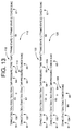
- the wheel information generator 100 With the detailed and abridged wheel information generating portions 102, 104 being activated when the detected tire air pressure is normal, the wheel information generator 100 generates NORMAL wheel information 110 consisting of detailed wheel information 112 and abridged wheel information 114, as indicated in Fig. 13.
- the detailed wheel information 112, which is generated by the detailed wheel information generating portion 102, is the sane as the NORMAL wheel information 50 shown in Fig. 4.
- the abridged wheel information 114 which is generated by the abridged wheel information generating portion 104, is the same as the ABRUPT TIRE PRESSURE REDUCTION wheel information 60 also shown in Fig. 4.
- the wheel information generator 100 With the detailed and abridged wheel information generating portions 102, 104 and the abnormality information generating portion 106 being activated when the detected tire air pressure is abnormal, the wheel information generator 100 generates ABNORMAL wheel information 120 consisting of detailed wheel information 122, abridged wheel information 124, and abnormality information 126, as indicated in Fig. 13.
- the detailed wheel information 122 and the abridged wheel information 124, which are the same as the NORMAL wheel information 50, are generated by the detailed and abridged information generating portions 102, 104, respectively.
- the abnormality information 126 which is generated by the abnormality information generating portion 106, is the same as the ABRUPT TIRE PRESSURE REDUCTION wheel information 90 shown in Fig. 11.
- TRAILER data 130 included in the detailed wheel information 112, 122 represent the total volume of the information 112, 122, and indicate that the information 112, 122 is the detailed wheel information which includes both the AIR PRESSURE data 54 and the TIRE TEMPERATURE data 55.
- TRAILER data 132 included in the abridged wheel information 114, 124 represent the total volume of the information 114, 124, and indicate that the information 114, 124 is the abridged wheel information which includes the AIR PRESSURE data 64 but does not include TIRE TEMPERATURE data.
- TRAILER data 134 included in the abnormality information 126 represent the total volume of the information 126, and indicate that the information 126 is the abnormality information which merely indicates that the tire air pressure is abnormal.
- the ratio of reception of at least one of these kinds of information is higher than the reception ratio where one of different kinds of information is selectively transmitted with a predetermined cycle time.
- the fourth embodiment of Fig1. 12-13 is adapted such that the NORMAL wheel information 110 or the ABNORMAL wheel information 120 is selectively transmitted from the transmitter 18, depending upon the detected tire air pressure of the wheel 10.
- the transmitter 18 may be considered to have a first and a second transmitting portion which are operated when the tire air pressure is normal and abnormal, respectively, so that the detailed wheel information 112 and the abridged wheel information 114 generated by the wheel information generator 100 are successively transmitted by the first transmitting portion when the tire air pressure is normal, and so that the detailed wheel information 122, the abridged wheel information 124 and the abnormality information 126 generated by the wheel information generator 100 are successively transmitted by the second transmitting portion when the tire air pressure is abnormal.
- the wheel information generator 100 may be adapted to generate all of the three different kinds of information 112 (122), 114 (124), 126, irrespective of whether the detected tire air pressure is lower than the preset value or not.
- the wheel information generator 100 may be modified to include only two of the detailed wheel information generating portion 102, the abridged wheel information generating portion 104, and the abnormality information generating portion 106.
- the generator 100 may include the detailed wheel information generating portion 102 and the abnormality information generating portion 106.
- the detailed wheel information generating portion 102 and the abnormality information generating portion 106 are both activated when the tire air pressure is abnormal, and only the detailed wheel information generating portion 102 is activated when the tire air pressure is normal. That is, ABNORMAL wheel information 140 consisting of detailed wheel information 142 and abnormality information 144 as shown in Fig.
- NORMAL wheel information 146 consisting of only the detailed wheel information as also shown in Fig. 15 is generated when the tire air pressure is normal.
- the different kinds of information are transmitted, they may be successively transmitted in any order.
- the detailed wheel information 142 may either precede or follow the abnormality information 144, provided the information 142 and the information 144 are successively transmitted.
- the wheel information may include information relating to the shape of the tire or the amount or condition of deformation of the tire, as well as information relating to the air pressure of the tire, information relating to the rate of reduction of the tire air pressure, and information relating to the tire temperature.
- the different information generating portions of the wheel information generator 16, 100 may be selectively activated, depending upon the rotating speed of the wheel 10.
- the reception ratio of the wheel information having a given volume decreases with an increase in the rotating speed of the wheel 10, as discussed above.
- the wheel information generator 100 may be adapted such that the abridged wheel information generating portion 104 is activated when the wheel speed is higher than a predetermined upper limit, and the detailed wheel information generating portion 102 is activated when the wheel speed is not higher than the upper limit.
- the wheel speed detector 108 may include a centrifugal force detecting portion adapted to detect the centrifugal force which increases with an increase in the wheel speed.
- the centrifugal force detecting portion may be a piezoelectric element adapted to detect a radial force which acts on a weight disposed on the tire or a tire holding portion of the wheel.
- An electric output signal of the piezoelectric element represents the centrifugal force from which the rotating speed of the wheel can be obtained.
- an acceleration sensor may be used for the wheel speed detector 108.
- a strain gage may be used as the above-indicated centrifugal force detecting portion of the wheel speed detector 108.
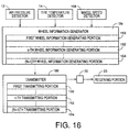
- a wheel information supply device includes a wheel information generator 156 and a transmitter 166.
- the wheel information generator 156 includes a plurality of wheel information generating portions 150, 152, 154, and the transmitter 166 includes a plurality of transmitting portions 160, 162, 164.
- only the first wheel information generating portion 150 and only the first transmitting portion 160 are activated when the wheel speed Vw is lower than a first threshold value Vws(1).
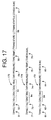
- the first wheel information generating portion 150 generates wheel information 170 shown in Fig. 17, and the first transmitting portion 160 transmits the wheel information 170 a predetermined number of times N(1).
- the wheel speed Vw is equal to an N-th threshold value Vws(n) or higher
- the (N+1)th wheel information generating portion 154 and the (N+1)th transmitting portion 164 are activated.
- the (N+1)th wheel information generating portion 154 generates wheel information 172 shown in Fig.
- the (N+1)th transmitting portion 164 transmits the wheel information 172 a predetermined number of times (N+1).
- the n-th wheel information generating portion 152 and the n-th transmitting portion 162 are activated.
- the n-th wheel information generating portion 152 generates wheel information 174 shown in Fig. 17, and the n-th transmitting portion 162 transmits the wheel information 174 a predetermined number of times M(n).
- both the wheel information generator 156 and the transmitter 166 are controlled depending upon the wheel speed Vw.
- the n-th threshold value Vws(n) and the number of times M(n) increase while the volume of the wheel information decreases as the number "n" increases from “1" to "N". That is, as the wheel speed Vw increases, the volume of the wheel information to be transmitted is reduced and the number of times of transmission of the wheel information is increased.
- the wheel information is transmitted with a predetermined cycle time, namely, at a predetermined time interval (e.g., ⁇ t).
- a predetermined cycle time namely, at a predetermined time interval (e.g., ⁇ t).
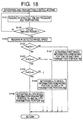
- step S101 to read in the detected tire air pressure and tire temperature, which are respectively detected by the air pressure detector 12 and the tire temperature detector 14 with the predetermined cycle time ⁇ t.
- step S102 is followed by step S102 to determine whether a preset cycle time has passed. If an affirmative decision (YES) is obtained in step S102, the control flow goes to step S103 to read in the wheel speed Vw, and to steps S104-S106 to determine whether the detected wheel speed Vw is equal to or higher than each of n-th threshold value Vws(n), more specifically, to determine one of three wheel speed ranges in which the detected wheel speed Vw lies.
- the first range has an upper limit equal to the first threshold value Vws(1)
- the second range is defined by a lower limit equal to the (n-1)th threshold value Vws(n-1) and an upper limit equal to the n-th threshold value Vws(n).
- the third range has a lower limit equal to the N-th threshold value Vws(N).
- step S104 When the detected wheel speed Vw is lower than the first threshold value Vws(1), a negative decision (NO) is obtained in step S104, and the control flow goes to step S107 in which the first wheel information generating portion 150 and the first transmitting portion 170 are selected and activated, so that the first wheel information 170 generated by the first wheel information generating portion 150 is transmitted by the first transmitting portion 160 the predetermined number of times M(1).
- step S104 When the detected wheel speed Vw is equal to or higher than the (n-1)th threshold value Vws(n-1) and is lower than the n-th threshold value Vws(n), an affirmative decision (YES) is obtained in step S104 while a negative decision (NO) is obtained in step S105, and the control flow goes to step S108 in which the n-th wheel information generating portion 152 and the n-th transmitting portion 162 are activated, so that the n-th wheel information 174 generated by the n-th wheel information generating device 152 is transmitted by the n-th transmitting portion 162 the predetermined number of times M(n).
- step S104 When the detected wheel speed Vw is equal to or higher than the N-th threshold value Vws(N), an affirmative decision (YES) is obtained in steps S104, S105 and S106, and the control flow goes to step S109 in which the (N+1)th wheel generating portion 154 and the (N+1)th transmitting portion 164 are activated, so that the (N+1)th wheel information 172 generated by the (N+1)th wheel information generating portion 154 is transmitted by the (N+1)th transmitting portion 164 the predetermined number of times M(N+1).
- both the operation of the wheel information generator 156 and the operation of the transmitter 166 are controlled depending upon the wheel speed Vw such that the volume of the wheel information to be transmitted decreases while the number of times of transmission of the wheel information increases, as the wheel speed Vw increases.
- This arrangement is effective to prevent reduction in the reception ratio of the wheel information when the wheel speed Vw is relatively high.
- the wheel information generator 156 need not include a plurality of wheel information generating portions (150, 152, 154) as provided in the above embodiment, provided the generator 156 is capable of generating different kinds of wheel information having respective different volumes.
- the transmitter 166 need not include a plurality of transmitting portions, provided the transmitter 166 is capable of transmitting the wheel information different number of times.
- the selected wheel information generating portion is operated only once to generate the corresponding wheel information, and the transmitter 166 transmits the sane wheel information the predetermined number of times, without the wheel information being updated with a change in the wheel speed Vw.
- the selected wheel information generating portion may be operated the predetermined number of times so that the wheel information generated by each operation of the wheel information generating portion is transmitted. This arrangement permits updating of the wheel information with a change in the wheel speed Vw.
- the generated wheel information may be transmitted the predetermined number of times M(n), either continuously without a non-transmission time between the successive transmissions, or at a predetermined time interval with a non-transmission time between the successive transmissions. In the latter case, the frequency of transmission of the wheel information increases with a decrease in the volume of the wheel information.
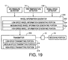
- the wheel information generator 200 includes a low-speed wheel information generating portion 202, a medium-speed wheel information generating portion 204 and a high-speed wheel information generating portion 206.
- the transmitter 208 includes a low-speed transmitting portion 210, a medium-speed transmitting portion 212 and a high-speed transmitting portion 214.
- the low-speed, medium-speed and high-speed wheel information generating portions 202, 204, 206 respectively generate the first wheel information 170, the (N+1)th wheel information 174 and the n-th wheel information 172 as low-speed wheel information, medium-speed wheel information and high-speed wheel information. These generating portions 202, 204, 206 are all activated to generate the respective kinds of wheel information 170, 174, 172 with a predetermined cycle time.
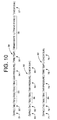
- the low-speed, medium-speed and high-speed transmitting portions 210, 212, 214 of the transmitter 208 are arranged to transmit the above-indicated three kinds of wheel information 170, 174, 172 according to respective three transmission patterns shown in Fig. 21.
- One of these three transmitting portions 210, 212, 214 is selected depending upon the detected wheel speed Vw.
- all of the three transmission patterns (low-speed, medium-speed and high-speed transmission patterns)
- all of the three kinds of wheel information 170, 172, 174 are transmitted.
- the three transmission patterns have different proportions of the numbers of transmission of the individual kinds of wheel information per each transmitting operation of the transmitter 208.
- the transmission patterns are stored in the ROM of the transmitter 208.
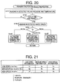
- One of the three transmitting portions 210, 212, 214 which operate according to the respective transmission patterns is selected and activated depending upon the detected wheel speed Vw, according to a transmitting portion selecting routine illustrated in the flow chart of Fig. 20.
- the routine of Fig. 20 has steps S151, S152 and S153 which are identical with step S101, S102 and S103 in Fig. 18.
- Step S153 is followed by step S154 to determine one of three ranges in which the detected wheel speed Vw lies. Namely, when the wheel speed Vw is lower than a threshold Vs2, the control flow goes to step S155 to select and activate the low-speed transmitting portion 210, so that the low-speed transmitting portion 210 is operated according to the low-speed transmission pattern to first transmit the low-speed wheel information 170 a predetermined first number of times L1, then transmit the medium-speed wheel information 174 a predetermined second number of times L2, and finally transmit the high-speed wheel information 172. According to the low-speed transmission pattern, L1 ⁇ L2 ⁇ L3.
- the control flow goes to step S156 to select and activate the medium-speed transmitting portion 212, so that the medium-speed transmitting portion 212 is operated according to the medium-speed transmission pattern to first transmit the low-speed wheel information 170 a predetermined first number of times M1, then transmit the medium-speed wheel information 174 a predetermined second number of times M2, and finally transmit the high-speed wheel information 172 a predetermined third number of times M3.
- step S157 When the detected wheel speed Vw is equal to or higher than the threshold Vs1, the control flow goes to step S157 to select and activate the high-speed transmitting portion 214, so that the high-speed transmitting portion 214 is operated according to the high-speed transmission pattern to first transmit the low-speed wheel information 170 a predetermined first number of times H1, then transmit the medium-speed wheel information 174 a predetermined second number of times H2, and finally transmit the high-speed wheel information 172 a predetermined third number of times H.
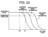
- the reception ratio of the wheel information decreases with an increase in the rotating speed of the wheel 10, and decreases with an increase in the volume of the wheel information while the wheel speed is constant.
- the wheel speed at which the reception ratio falls below a permissible lower limit decreases with an increase in the volume of the wheel information.
- the reception ratios of the medium-speed wheel information 174 and the high-speed wheel information 172 are higher than the permissible lower limit, even after the wheel speed Vw is higher than the threshold Vs1, until the wheel speed has increased to respective upper limits. Accordingly, the medium-speed wheel information 172 and high-speed wheel information 174 having relatively small volumes are transmitted when the wheel speed Vw is relatively high. In this case, the total volume of the wheel information is relatively small, and the number of items represented by the wheel information is reduced.
- the reception ratio can be increased by increasing the number of transmissions of the wheel information. In this case, however, the required amount of electric energy is increased, and the service life of the battery used in the transmitter 208 is shortened.
- the ratio of the number of the small-volume wheel information (172; 172, 174) to the number of the large-volume wheel information (170; 170, 174) is increased with an increase in the wheel speed Vw, so that the reception ratio is made relatively high even when the vehicle speed is relatively high.
- This arrangement has a possibility that the large-volume wheel information can be received when the vehicle speed is relatively high, so that the number of items represented by the received wheel information can be made relatively large even when the vehicle speed is relatively high.
- the reception ratios of the medium-speed and high-speed wheel information 174, 172 can be increased. Even where the numbers of the three kinds of wheel information for each wheel speed range are equal to each other and the total numbers of times Ln, Mn, Hn are equal to each other, the different transmission patterns can be obtained for the three wheel speed ranges, if the transmission cycle times are different for the respective three wheel speed ranges.
- the numbers of times of transmission of the three kinds of wheel information are equal to each other for one of the three wheel speed ranges, while those for the other speed ranges are different from each other.
- the proportions of the numbers of times of transmission of the three kinds of wheel information can be made different from each other.
- the low-speed wheel information 170, medium-speed wheel information 174 and high-speed wheel information 172 are all generated and transmitted, irrespective of the wheel speed.
- all of the three kinds of wheel information need not be transmitted.
- at least one of L1, L2, L3, M1, M2, M3, H1, H2 and H3 may be zero.
- M2, M3 and H3 are desirably "1" or larger. That is, it is desirable to transmit the medium-speed wheel information 174 and the high-speed wheel information 172 when the wheel speed is in the medium range, and transmit the high-speed wheel information 172 when the wheel speed is in the high range.
- the order of transmission of the three kinds of wheel information 170, 174, 172 can be changed depending upon the detected wheel speed Vw. That is, the low-speed wheel information 170 is initially transmitted when the wheel speed is in the low range, and the medium-speed wheel information 174 is initially transmitted when the wheel speed is in the medium range. Further, the high-speed wheel information 172 is initially transmitted when the wheel speed is in the high range.
- the same wheel information e.g., 170
- the transmissions need not be successive, and the different kinds of wheel information 170, 172, 174 may be transmitted at random. For instance, the wheel information 170 may be transmitted immediately before and after the wheel information 174.
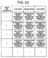
- Fig. 23 shows a combination of generation patterns for the three different wheel speed ranges, according to an eighth embodiment of the invention.
- each of the three kinds of wheel information generated is transmitted only once or a predetermined number of times, according to a predetermined rule.
- the low-speed wheel information 170, the medium-speed wheel information 174 and the high-speed wheel information 172 are generated in this order.
- the medium-speed wheel information 174, the high-speed wheel information 172 and the low-speed wheel information 170 are generated in this order.
- the high-speed wheel information 172, the medium-speed wheel information 174 and the low-speed wheel information 170 are generated in this order.
- the wheel information is generated and transmitted with the predetermined cycle time ⁇ t, so that the wheel information received can be updated with a change in the wheel condition (tire air pressure).
- a vehicle wheel information supply device for supplying wheel information relating to a state of a wheel (10) of a vehicle, including a wheel state detector (12, 14, 108) for detecting the state of the wheel, a wheel information generator (16, 100, 156) for generating the wheel information relating to the state of the wheel, on the basis of an output of the wheel state detector, a transmitter for transmitting the wheel information, and a receiver (28) which receives the wheel information transmitted by the transmitter, the wheel state detector, the wheel information generator and the transmitter being disposed on the wheel while the receiver being disposed on a body of said vehicle, wherein the wheel information generator is capable of selectively generating different kinds of wheel information having respective different volumes, and at least one of the wheel information generator and the transmitter (18, 166, 208) operates in a manner which changes depending upon at least one parameter indicative of the state of the wheel (10), which at least one parameter is detected by the wheel state detector.
Landscapes
- Engineering & Computer Science (AREA)
- Mechanical Engineering (AREA)
- Computer Networks & Wireless Communication (AREA)
- Measuring Fluid Pressure (AREA)
- Arrangements For Transmission Of Measured Signals (AREA)
Applications Claiming Priority (4)
| Application Number | Priority Date | Filing Date | Title |
|---|---|---|---|
| JP37041398 | 1998-12-25 | ||
| JP37041398 | 1998-12-25 | ||
| JP22542199 | 1999-08-09 | ||
| JP22542199A JP3499470B2 (ja) | 1998-12-25 | 1999-08-09 | 車輪状態関連情報供給装置およびタイヤ異常状態報知装置 |
Publications (2)
| Publication Number | Publication Date |
|---|---|
| EP1013483A2 true EP1013483A2 (fr) | 2000-06-28 |
| EP1013483A3 EP1013483A3 (fr) | 2003-04-02 |
Family
ID=26526630
Family Applications (1)
| Application Number | Title | Priority Date | Filing Date |
|---|---|---|---|
| EP99125661A Withdrawn EP1013483A3 (fr) | 1998-12-25 | 1999-12-22 | Dispositif de transmission d'informations issues d'une roue de véhicule et dispositif de détection d'anomalie pour un pneumatique |
Country Status (3)
| Country | Link |
|---|---|
| US (1) | US6275148B1 (fr) |
| EP (1) | EP1013483A3 (fr) |
| JP (1) | JP3499470B2 (fr) |
Cited By (13)
| Publication number | Priority date | Publication date | Assignee | Title |
|---|---|---|---|---|
| EP1214208A1 (fr) * | 1999-08-16 | 2002-06-19 | The Goodyear Tire & Rubber Company | Procede et systeme pour surveiller un etat dynamique d'un element rotatif, notamment d'un pneumatique |
| WO2004030948A1 (fr) * | 2002-10-01 | 2004-04-15 | Piezotag Limited | Unite de telemetrie |
| EP1468847A1 (fr) * | 2003-04-18 | 2004-10-20 | Pacific Industrial Co., Ltd. | Appareil pour surveiller des conditions des pneus |
| WO2008103973A1 (fr) * | 2007-02-23 | 2008-08-28 | Continental Automotive Systems Us, Inc. | Signaux de radio fréquence robustes |
| CN103889745A (zh) * | 2011-08-09 | 2014-06-25 | 大陆汽车系统公司 | 用于轮胎压力监控系统的协议误解避免设备和方法 |
| US9446636B2 (en) | 2014-02-26 | 2016-09-20 | Continental Automotive Systems, Inc. | Pressure check tool and method of operating the same |
| US9517664B2 (en) | 2015-02-20 | 2016-12-13 | Continental Automotive Systems, Inc. | RF transmission method and apparatus in a tire pressure monitoring system |
| US9776463B2 (en) | 2011-08-09 | 2017-10-03 | Continental Automotive Systems, Inc. | Apparatus and method for data transmissions in a tire pressure monitor |
| US10220660B2 (en) | 2015-08-03 | 2019-03-05 | Continental Automotive Systems, Inc. | Apparatus, system and method for configuring a tire information sensor with a transmission protocol based on vehicle trigger characteristics |
| CN112976961A (zh) * | 2021-03-25 | 2021-06-18 | 武汉拾易鑫科技有限公司 | 基于机器视觉和大数据分析的汽车行驶安全状态实时监测预警方法 |
| WO2021127700A1 (fr) * | 2019-12-18 | 2021-06-24 | Continental Automotive Systems, Inc. | Nombre réduit d'états dans un système de surveillance de pression de pneu |
| EP3967526A1 (fr) * | 2020-09-14 | 2022-03-16 | Continental Reifen Deutschland GmbH | Procédé de transmission sans fil des informations d'un module de roue disposé sur une roue vers une unité de réception et module de roue |
| WO2024260996A1 (fr) * | 2023-06-22 | 2024-12-26 | Continental Automotive Technologies GmbH | Procédé pour le pilotage d'une unité roue simplifiée appartenant à un système de surveillance de la pression des pneumatiques d'un véhicule automobile |
Families Citing this family (78)
| Publication number | Priority date | Publication date | Assignee | Title |
|---|---|---|---|---|
| FR2794065B1 (fr) * | 1999-05-28 | 2001-06-22 | Sagem | Systeme securise de controle de la pression d'un pneumatique |
| JP3510164B2 (ja) | 1999-10-06 | 2004-03-22 | トヨタ自動車株式会社 | 車輪状態情報供給装置および車輪状態情報供給・受信装置 |
| US6571481B1 (en) * | 2000-05-16 | 2003-06-03 | Jeffrey N. Weiss | Automatic low tire pressure detector |
| JP4611537B2 (ja) * | 2000-06-09 | 2011-01-12 | 本田技研工業株式会社 | 車載用タイヤ空気圧検知装置 |
| JP3561213B2 (ja) * | 2000-07-18 | 2004-09-02 | 住友ゴム工業株式会社 | タイヤ空気圧低下警報装置および方法 |
| US8266465B2 (en) | 2000-07-26 | 2012-09-11 | Bridgestone Americas Tire Operation, LLC | System for conserving battery life in a battery operated device |
| US7161476B2 (en) | 2000-07-26 | 2007-01-09 | Bridgestone Firestone North American Tire, Llc | Electronic tire management system |
| US7150187B2 (en) * | 2000-11-27 | 2006-12-19 | Pirelli Pneumatici S.P.A. | System and method for monitoring deformations of a moving tire |
| DE10144326B4 (de) * | 2001-09-10 | 2005-09-22 | Siemens Ag | Verfahren und System zur Überwachung eines Reifenluftdrucks |
| DE10144359A1 (de) * | 2001-09-10 | 2003-04-03 | Siemens Ag | Vorrichtung zum Messen des Reifendrucks eines jeden Rades eines Kraftfahrzeug und Verfahren zum Betreiben der Vorrichtung |
| JP3826838B2 (ja) * | 2001-09-18 | 2006-09-27 | トヨタ自動車株式会社 | 前後力制御装置 |
| US6864803B2 (en) * | 2001-10-12 | 2005-03-08 | Lear Corporation | System and method for tire pressure monitoring using CDMA tire pressure signals |
| US6693522B2 (en) | 2001-10-12 | 2004-02-17 | Lear Corporation | System and method for tire pressure monitoring including automatic tire location recognition |
| JP4013521B2 (ja) * | 2001-10-24 | 2007-11-28 | マツダ株式会社 | 車両用タイヤの空気圧情報表示装置 |
| US6691567B2 (en) | 2002-03-01 | 2004-02-17 | Lear Corporation | System and method for tire pressure monitoring including automatic tire location recognition |
| US20030164034A1 (en) * | 2002-03-01 | 2003-09-04 | Lear Corporation | System and method for using a saw based RF transmitter for FM transmission in a TPM |
| US6668636B2 (en) | 2002-03-01 | 2003-12-30 | Lear Corporation | System and method for tire pressure monitoring including tire location recognition |
| US6788193B2 (en) | 2002-03-01 | 2004-09-07 | Lear Corporation | System and method for tire pressure monitoring providing automatic tire location recognition |
| US6725712B1 (en) | 2002-03-01 | 2004-04-27 | Lear Corporation | System and method for tire pressure monitoring with automatic tire location recognition |
| US6876265B2 (en) * | 2002-03-01 | 2005-04-05 | Lear Corporation | System and method for using a saw based RF transmitter for AM modulated transmission in a TPM |
| US20030164759A1 (en) * | 2002-03-01 | 2003-09-04 | Lear Corporation | System and method for tire pressure monitoring with optimal tire pressure indication during tire pressure adjustment |
| US7154414B2 (en) | 2002-03-01 | 2006-12-26 | Lear Corporation | System and method for remote tire pressure monitoring |
| US6647773B2 (en) | 2002-03-01 | 2003-11-18 | Lear Corporation | System and method for integrated tire pressure monitoring and passive entry |
| US20030164760A1 (en) * | 2002-03-01 | 2003-09-04 | Lear Corporation | System and method for tire pressure monitoring using vehicle radio |
| US6829924B2 (en) | 2002-03-01 | 2004-12-14 | Lear Corporation | Tire pressure monitoring system with low frequency initiation approach |
| JP3951763B2 (ja) | 2002-03-19 | 2007-08-01 | トヨタ自動車株式会社 | 車輪状態取得装置 |
| US20030179086A1 (en) * | 2002-03-25 | 2003-09-25 | Lear Corporation | System for remote tire pressure monitoring with low frequency initiation antenna |
| US6838985B2 (en) * | 2002-03-25 | 2005-01-04 | Lear Corporation | System and method for remote tire pressure monitoring with low frequency initiation |
| JP3960112B2 (ja) | 2002-04-22 | 2007-08-15 | トヨタ自動車株式会社 | タイヤ状態検出・通信装置 |
| US20030214395A1 (en) * | 2002-05-14 | 2003-11-20 | Johnson Controls Technology Company | Removable tire characteristic receiver |
| DE10223214A1 (de) * | 2002-05-24 | 2003-12-18 | Siemens Ag | Verfahren zum Zuordnen von Reifenmodulen zu Radpositionen eines Reifendrucküberwachungssytems für ein Kraftfahrzeug und Vorrichtung zum Überwachen des Reifendrucks |
| US7079033B2 (en) | 2002-06-05 | 2006-07-18 | Denso Corporation | ID registration method for tire pressure sensor, ID registration apparatus, ID registration tool for tire pressure monitoring system, and tire with air pressure sensor |
| JP3935000B2 (ja) * | 2002-06-26 | 2007-06-20 | 株式会社デンソー | 車両制御システムと、これを実現するためのタイヤ空気圧監視装置、タイヤ空気圧センサ及びタイヤ空気圧監視装置用id登録ツール |
| US6980099B2 (en) * | 2002-07-01 | 2005-12-27 | Siemens Aktiengesellschaft | Arrangement for monitoring at least one parameter for a number of motor vehicle wheels |
| US6972672B2 (en) * | 2002-07-03 | 2005-12-06 | Siemens Vdo Automotive Corporation | Tire sensor localization utilizing speed corrected frequency |
| US6952160B1 (en) * | 2002-08-07 | 2005-10-04 | Ford Global Technologies, Llc | Method and apparatus, for identifying the location of pressure sensors in a tire pressure monitoring system |
| US6982636B1 (en) * | 2002-08-07 | 2006-01-03 | Ford Global Technologies, Llc | Method and system for mitigating false alarms in a tire pressure monitoring system for an automotive vehicle |
| JP3997864B2 (ja) | 2002-08-14 | 2007-10-24 | トヨタ自動車株式会社 | 車輪状態取得装置および車両状態取得装置 |
| JP4637582B2 (ja) * | 2002-08-30 | 2011-02-23 | 株式会社ブリヂストン | 車輪状態監視システム |
| JP4016773B2 (ja) * | 2002-09-13 | 2007-12-05 | トヨタ自動車株式会社 | 車輪識別情報登録支援装置 |
| CN1290717C (zh) * | 2003-05-25 | 2006-12-20 | 朱鹏飞 | 汽车轮胎、机器、急减速故障预警系统 |
| US7289022B2 (en) * | 2003-06-05 | 2007-10-30 | Toyota Jidosha Kabushiki Kaisha | Communication system and method for communicating between a tire/wheel assembly and a vehicle body |
| JP4168857B2 (ja) | 2003-07-31 | 2008-10-22 | トヨタ自動車株式会社 | 識別情報検査方法及び情報取得装置 |
| DE10352539B4 (de) * | 2003-11-11 | 2007-04-12 | Siemens Ag | System zum Überwachen eines luftbereiften Fahrzeugs, Signalauswerteverfahren sowie Fahrzeugreifen |
| JP4066947B2 (ja) * | 2003-12-19 | 2008-03-26 | 株式会社デンソー | タイヤ空気圧検出装置 |
| JP4030990B2 (ja) * | 2004-09-14 | 2008-01-09 | 株式会社ケーヒン | 乗員保護装置の通信制御装置 |
| JP3895347B2 (ja) | 2004-11-19 | 2007-03-22 | 横浜ゴム株式会社 | タイヤ変形量算出方法及びタイヤ変形量算出装置 |
| US8565959B2 (en) * | 2004-12-03 | 2013-10-22 | The Goodyear Tire & Rubber Company | Method for detection of low leak rates in a tire |
| US7817023B2 (en) * | 2004-12-15 | 2010-10-19 | The Yokohama Rubber Co., Ltd. | Wheel information acquiring system |
| US7224269B2 (en) * | 2004-12-15 | 2007-05-29 | Ford Global Technologies, Llc | Method and system for resetting tire pressure monitoring system for an automotive vehicle |
| JP4548113B2 (ja) * | 2004-12-22 | 2010-09-22 | 株式会社デンソー | タイヤ空気圧検出装置 |
| JP4604755B2 (ja) * | 2005-02-15 | 2011-01-05 | 横浜ゴム株式会社 | タイヤ情報送信装置およびこれを用いたタイヤ情報取得システム |
| JP2006306344A (ja) * | 2005-05-02 | 2006-11-09 | Nissan Motor Co Ltd | タイヤ空気圧モニタ装置 |
| US7369043B2 (en) * | 2005-05-11 | 2008-05-06 | Ford Global Technologies, Llc | Method and apparatus for automatically identifying the location of pressure sensors in a tire pressure monitoring system |
| FR2889610B1 (fr) * | 2005-08-04 | 2007-10-19 | Siemens Vdo Automotive Sas | Procede de transmission d'un signal electromagnetique de requete d'identification a destination d'un boitier electronique monte sur une roue d'un vehicule |
| JP4922585B2 (ja) * | 2005-09-09 | 2012-04-25 | 中央精機株式会社 | タイヤ監視装置のデータ生成出力装置及びタイヤ監視装置 |
| US7570157B2 (en) * | 2005-10-24 | 2009-08-04 | Ford Global Technologies, Llc | Method and apparatus for adjusting the pressure sensor measurement range in a tire pressure monitoring system |
| US7705717B2 (en) * | 2005-11-30 | 2010-04-27 | Ford Global Technologies | Method and apparatus for receiving signals from a sensor into a tire pressure monitoring system |
| JP2007261288A (ja) * | 2006-03-27 | 2007-10-11 | Alps Electric Co Ltd | タイヤ情報検出装置 |
| US7269530B1 (en) * | 2006-05-02 | 2007-09-11 | Universal Scientific Industrial Co., Ltd. | Wireless transmission method for tire detection signals |
| JP4281787B2 (ja) * | 2006-11-24 | 2009-06-17 | トヨタ自動車株式会社 | 車載異常警報装置 |
| US8392048B2 (en) * | 2006-11-30 | 2013-03-05 | Hunter Engineering Company | Integrated tire pressure diagnostic system and method |
| JP2008149863A (ja) * | 2006-12-15 | 2008-07-03 | Seetron Inc | タイヤ状態監視装置 |
| WO2009006518A1 (fr) * | 2007-07-03 | 2009-01-08 | Continental Automotive Systems Us, Inc. | Capteur universel de contrôle de pression de pneu |
| US8560159B2 (en) * | 2008-04-29 | 2013-10-15 | Huf Hulsbeck & Furst Gmbh & Co. Kg | Method, system and system components for wireless tire pressure monitoring |
| JP5246077B2 (ja) * | 2009-07-09 | 2013-07-24 | 日産自動車株式会社 | タイヤ空気圧検出装置、タイヤ空気圧監視システムおよびタイヤ空気圧送信方法 |
| US8659412B2 (en) | 2009-12-10 | 2014-02-25 | Continental Automotive Systems, Inc. | Tire pressure monitoring apparatus and method |
| FR2955414B1 (fr) * | 2010-01-15 | 2012-02-03 | Johnson Controls Tech Co | Procede d'echange de signaux entre un capteur de pression de pneu et une unite centrale equipant un vehicule automobile. |
| US8751092B2 (en) | 2011-01-13 | 2014-06-10 | Continental Automotive Systems, Inc. | Protocol protection |
| KR101599365B1 (ko) | 2011-08-09 | 2016-03-14 | 컨티넨탈 오토모티브 시스템즈 인코포레이티드 | 타이어 압력 모니터링 시스템에서 프로토콜 배열 |
| US9676238B2 (en) | 2011-08-09 | 2017-06-13 | Continental Automotive Systems, Inc. | Tire pressure monitor system apparatus and method |
| CN103717416B (zh) | 2011-08-09 | 2019-02-22 | 大陆汽车系统公司 | 轮胎压力监控设备和方法 |
| JP5795522B2 (ja) * | 2011-11-15 | 2015-10-14 | 株式会社東海理化電機製作所 | タイヤ空気圧監視システムの制御装置 |
| WO2016203741A1 (fr) * | 2015-06-15 | 2016-12-22 | 株式会社ブリヂストン | Procédé de calcul de charge |
| FR3060126B1 (fr) * | 2016-12-08 | 2020-06-26 | Continental Automotive France | Procede pour obtenir une information redondante de la vitesse d'un vehicule |
| DE102018212839A1 (de) * | 2018-08-01 | 2020-02-06 | Ford Global Technologies, Llc | System und ein Verfahren zum Überwachen eines Reifendrucks |
| CN113923833B (zh) * | 2021-10-20 | 2023-11-07 | 重庆交通大学 | 一种基于减速带的低交通量隧道智能节能控制系统 |
| JP7848751B2 (ja) * | 2022-10-20 | 2026-04-21 | トヨタ自動車株式会社 | 車輪状態取得システム |
Citations (2)
| Publication number | Priority date | Publication date | Assignee | Title |
|---|---|---|---|---|
| JPH0513802U (ja) | 1991-04-08 | 1993-02-23 | 太平洋工業株式会社 | タイヤ空気圧警報システム |
| JPH11225421A (ja) | 1998-02-03 | 1999-08-17 | Je Kk | 結束用バンド |
Family Cites Families (19)
| Publication number | Priority date | Publication date | Assignee | Title |
|---|---|---|---|---|
| US4319220A (en) | 1976-08-31 | 1982-03-09 | Dennis G. Pappas | Alarm system for monitoring pressurized vehicular tires |
| DE3703128A1 (de) | 1987-02-03 | 1988-08-11 | Continental Gummi Werke Ag | Ueberwachungsverfahren und -vorrichtung fuer dynamisch beanspruchte gummiartikel |
| CH681931A5 (fr) * | 1991-05-29 | 1993-06-15 | Ascom Zelcom Ag | |
| JPH0513802A (ja) | 1991-06-28 | 1993-01-22 | Canon Inc | 光電変換装置 |
| DE4205911A1 (de) | 1992-02-26 | 1993-09-02 | Uwatec Ag | Kontrollvorrichtung fuer den luftdruck von luftbereiften fahrzeugraedern |
| GB9220234D0 (en) | 1992-09-24 | 1992-11-04 | Otter Controls Ltd | Tyre condition monitoring |
| DE4303583C2 (de) | 1993-02-08 | 1996-02-22 | Alpha Beta Electronics Ag | Ventil mit einer Einrichtung zur Erzeugung eines drahtlos übermittelbaren Druckabnahme-Anzeigesignals für Fahrzeugreifen |
| US5600301A (en) | 1993-03-11 | 1997-02-04 | Schrader Automotive Inc. | Remote tire pressure monitoring system employing coded tire identification and radio frequency transmission, and enabling recalibration upon tire rotation or replacement |
| US5540892A (en) * | 1993-04-22 | 1996-07-30 | Kidd; Marvin L. | Urinalysis collection and testing kit and method |
| US5473938A (en) * | 1993-08-03 | 1995-12-12 | Mclaughlin Electronics | Method and system for monitoring a parameter of a vehicle tire |
| US5463374A (en) * | 1994-03-10 | 1995-10-31 | Delco Electronics Corporation | Method and apparatus for tire pressure monitoring and for shared keyless entry control |
| JPH10504783A (ja) | 1994-08-31 | 1998-05-12 | オター コントロールズ リミテッド | タイヤ状態監視システム |
| US5581023A (en) * | 1994-10-31 | 1996-12-03 | Handfield; Michael | Pressure transducer for monitoring a pneumatic tire |
| JP3579150B2 (ja) | 1994-11-14 | 2004-10-20 | 横浜ゴム株式会社 | 車両のタイヤ内空気圧モニター装置 |
| DE69431127T2 (de) | 1994-11-22 | 2003-03-27 | Schrader-Bridgeport International, Inc. | Reifendruckfernüberwachungssystem |
| US5825286A (en) | 1995-05-08 | 1998-10-20 | Semisystems, Inc. | Vehicular data collection and transmission system and method |
| US5731516A (en) | 1995-06-07 | 1998-03-24 | Handfield; Michael | System and method for monitoring a pneumatic tire |
| DE19522486C2 (de) | 1995-06-21 | 1999-04-22 | Duerrwaechter E Dr Doduco | Verfahren zum Betreiben einer Einrichtung zum Überwachen und drahtlosen Signalisieren einer Druckänderung in Luftreifen an Fahrzeugen |
| US5717376A (en) | 1996-09-03 | 1998-02-10 | United Technologies Automotive, Inc. | System for determining failure of remote sensing device |
-
1999
- 1999-08-09 JP JP22542199A patent/JP3499470B2/ja not_active Expired - Fee Related
- 1999-12-17 US US09/466,073 patent/US6275148B1/en not_active Expired - Lifetime
- 1999-12-22 EP EP99125661A patent/EP1013483A3/fr not_active Withdrawn
Patent Citations (2)
| Publication number | Priority date | Publication date | Assignee | Title |
|---|---|---|---|---|
| JPH0513802U (ja) | 1991-04-08 | 1993-02-23 | 太平洋工業株式会社 | タイヤ空気圧警報システム |
| JPH11225421A (ja) | 1998-02-03 | 1999-08-17 | Je Kk | 結束用バンド |
Cited By (21)
| Publication number | Priority date | Publication date | Assignee | Title |
|---|---|---|---|---|
| EP1214208A1 (fr) * | 1999-08-16 | 2002-06-19 | The Goodyear Tire & Rubber Company | Procede et systeme pour surveiller un etat dynamique d'un element rotatif, notamment d'un pneumatique |
| WO2004030948A1 (fr) * | 2002-10-01 | 2004-04-15 | Piezotag Limited | Unite de telemetrie |
| AU2003269243B2 (en) * | 2002-10-01 | 2008-10-16 | Piezotag Limited | Telemetry unit |
| US7733241B2 (en) | 2002-10-01 | 2010-06-08 | Piezotag Limited | Telemetry unit |
| EP1780056A3 (fr) * | 2002-10-01 | 2011-03-09 | Piezotag Limited | Unité télémétrique |
| EP1468847A1 (fr) * | 2003-04-18 | 2004-10-20 | Pacific Industrial Co., Ltd. | Appareil pour surveiller des conditions des pneus |
| US6931923B2 (en) | 2003-04-18 | 2005-08-23 | Pacific Industrial Co., Ltd. | Tire condition monitoring apparatus |
| WO2008103973A1 (fr) * | 2007-02-23 | 2008-08-28 | Continental Automotive Systems Us, Inc. | Signaux de radio fréquence robustes |
| US7924148B2 (en) | 2007-02-23 | 2011-04-12 | Continental Automotive Systems Us, Inc | Robust radio frequency signals |
| CN103889745B (zh) * | 2011-08-09 | 2016-08-31 | 大陆汽车系统公司 | 用于轮胎压力监控系统的协议误解避免设备和方法 |
| CN103889745A (zh) * | 2011-08-09 | 2014-06-25 | 大陆汽车系统公司 | 用于轮胎压力监控系统的协议误解避免设备和方法 |
| US9776463B2 (en) | 2011-08-09 | 2017-10-03 | Continental Automotive Systems, Inc. | Apparatus and method for data transmissions in a tire pressure monitor |
| US9446636B2 (en) | 2014-02-26 | 2016-09-20 | Continental Automotive Systems, Inc. | Pressure check tool and method of operating the same |
| US9517664B2 (en) | 2015-02-20 | 2016-12-13 | Continental Automotive Systems, Inc. | RF transmission method and apparatus in a tire pressure monitoring system |
| US10220660B2 (en) | 2015-08-03 | 2019-03-05 | Continental Automotive Systems, Inc. | Apparatus, system and method for configuring a tire information sensor with a transmission protocol based on vehicle trigger characteristics |
| WO2021127700A1 (fr) * | 2019-12-18 | 2021-06-24 | Continental Automotive Systems, Inc. | Nombre réduit d'états dans un système de surveillance de pression de pneu |
| US11179978B2 (en) | 2019-12-18 | 2021-11-23 | Continental Automotive Systems, Inc. | Reduced number of states in a tire pressure monitoring system |
| EP3967526A1 (fr) * | 2020-09-14 | 2022-03-16 | Continental Reifen Deutschland GmbH | Procédé de transmission sans fil des informations d'un module de roue disposé sur une roue vers une unité de réception et module de roue |
| CN112976961A (zh) * | 2021-03-25 | 2021-06-18 | 武汉拾易鑫科技有限公司 | 基于机器视觉和大数据分析的汽车行驶安全状态实时监测预警方法 |
| WO2024260996A1 (fr) * | 2023-06-22 | 2024-12-26 | Continental Automotive Technologies GmbH | Procédé pour le pilotage d'une unité roue simplifiée appartenant à un système de surveillance de la pression des pneumatiques d'un véhicule automobile |
| FR3150143A1 (fr) * | 2023-06-22 | 2024-12-27 | Continental Automotive Technologies GmbH | Procédé pour le pilotage d’une unité roue simplifiée appartenant à un système de surveillance de la pression des pneumatiques d’un véhicule automobile |
Also Published As
| Publication number | Publication date |
|---|---|
| EP1013483A3 (fr) | 2003-04-02 |
| US6275148B1 (en) | 2001-08-14 |
| JP2000238515A (ja) | 2000-09-05 |
| JP3499470B2 (ja) | 2004-02-23 |
Similar Documents
| Publication | Publication Date | Title |
|---|---|---|
| EP1013483A2 (fr) | Dispositif de transmission d'informations issues d'une roue de véhicule et dispositif de détection d'anomalie pour un pneumatique | |
| US6340930B1 (en) | System and method for monitoring a condition of a vehicle tire | |
| EP1356960B1 (fr) | Appareil de détection/communication de l'état d'un pneumatique de véhicule et appareil de communication de données de pneumatique | |
| JP4606026B2 (ja) | タイヤ圧力監視システム | |
| EP0967095B1 (fr) | Procédé et appareil d'identification d'émetteurs à distance dans un véhicule | |
| US7019628B2 (en) | Tire monitoring and keyless entry system | |
| US6430484B1 (en) | Vehicle wheel information supply device which supplies smaller data set earlier than larger data set | |
| US7015801B1 (en) | Vehicle-controlled tire condition sensor communication utilizing fixed tire identification | |
| US7518495B2 (en) | Universal tire pressure monitor | |
| EP1092570B1 (fr) | Appareil et procédé de transmission pour un dispositif de surveillance de la pression de gonflage des pneumatiques d'un véhicule | |
| US7154414B2 (en) | System and method for remote tire pressure monitoring | |
| US20020084896A1 (en) | Tire condition sensor communication with tire location provided via vehicle-mounted identification units | |
| EP1216854A2 (fr) | Appareil et procédé de transmission pour un dispositif de surveillance de l'état des pneumatiques d'un véhicule | |
| US20030156022A1 (en) | Transmitter of tire condition monitoring apparatus and tire condition monitoring apparatus | |
| KR100363146B1 (ko) | 타이어 공기압 모니터장치와 모니터링 방법 | |
| US11198336B2 (en) | Transmission and receiving arrangement for a tire pressure detection device | |
| EP1536392A1 (fr) | Systeme de surveillance des etats de roues | |
| US20210221186A1 (en) | Tire pressure monitoring system | |
| US20060158324A1 (en) | System and method to facilitate idetifying location of a remote module | |
| US7557698B2 (en) | Wheel information processing device | |
| US7403105B2 (en) | Highly reliable direct-type tire inflation pressure sensing apparatus | |
| EP1384605B1 (fr) | Appareil de surveillance de condition de pneumatique | |
| JP4810894B2 (ja) | タイヤ空気圧の情報を受信するための車体側通信機、自車輪のタイヤ空気圧を検出して無線送信するタイヤ空気圧送信機、およびタイヤ空気圧監視システム | |
| JP4135712B2 (ja) | タイヤ空気圧検出装置 | |
| MXPA00001354A (en) | Method for communicating data in a remote tire pressure monitoring system |
Legal Events
| Date | Code | Title | Description |
|---|---|---|---|
| PUAI | Public reference made under article 153(3) epc to a published international application that has entered the european phase |
Free format text: ORIGINAL CODE: 0009012 |
|
| 17P | Request for examination filed |
Effective date: 19991222 |
|
| AK | Designated contracting states |
Kind code of ref document: A2 Designated state(s): AT BE CH CY DE DK ES FI FR GB GR IE IT LI LU MC NL PT SE |
|
| AX | Request for extension of the european patent |
Free format text: AL;LT;LV;MK;RO;SI |
|
| RIC1 | Information provided on ipc code assigned before grant |
Free format text: 7B 60C 23/04 A, 7B 60C 23/20 B, 7B 60T 8/00 B |
|
| PUAL | Search report despatched |
Free format text: ORIGINAL CODE: 0009013 |
|
| AK | Designated contracting states |
Kind code of ref document: A3 Designated state(s): AT BE CH CY DE DK ES FI FR GB GR IE IT LI LU MC NL PT SE Designated state(s): AT BE CH CY DE DK ES FI FR GB GR IE IT LI LU MC NL PT SE |
|
| AX | Request for extension of the european patent |
Extension state: AL LT LV MK RO SI |
|
| 17Q | First examination report despatched |
Effective date: 20030724 |
|
| AKX | Designation fees paid |
Designated state(s): DE FR GB |
|
| STAA | Information on the status of an ep patent application or granted ep patent |
Free format text: STATUS: THE APPLICATION IS DEEMED TO BE WITHDRAWN |
|
| 18D | Application deemed to be withdrawn |
Effective date: 20101125 |