EP1013496A2 - Anzeigeinstrument - Google Patents
Anzeigeinstrument Download PDFInfo
- Publication number
- EP1013496A2 EP1013496A2 EP99124706A EP99124706A EP1013496A2 EP 1013496 A2 EP1013496 A2 EP 1013496A2 EP 99124706 A EP99124706 A EP 99124706A EP 99124706 A EP99124706 A EP 99124706A EP 1013496 A2 EP1013496 A2 EP 1013496A2
- Authority
- EP
- European Patent Office
- Prior art keywords
- front frame
- cover plate
- spacer element
- display instrument
- instrument according
- Prior art date
- Legal status (The legal status is an assumption and is not a legal conclusion. Google has not performed a legal analysis and makes no representation as to the accuracy of the status listed.)
- Granted
Links
Images

Classifications
-
- B—PERFORMING OPERATIONS; TRANSPORTING
- B60—VEHICLES IN GENERAL
- B60K—ARRANGEMENT OR MOUNTING OF PROPULSION UNITS OR OF TRANSMISSIONS IN VEHICLES; ARRANGEMENT OR MOUNTING OF PLURAL DIVERSE PRIME-MOVERS IN VEHICLES; AUXILIARY DRIVES FOR VEHICLES; INSTRUMENTATION OR DASHBOARDS FOR VEHICLES; ARRANGEMENTS IN CONNECTION WITH COOLING, AIR INTAKE, GAS EXHAUST OR FUEL SUPPLY OF PROPULSION UNITS IN VEHICLES
- B60K35/00—Instruments specially adapted for vehicles; Arrangement of instruments in or on vehicles
- B60K35/20—Output arrangements, i.e. from vehicle to user, associated with vehicle functions or specially adapted therefor
- B60K35/21—Output arrangements, i.e. from vehicle to user, associated with vehicle functions or specially adapted therefor using visual output, e.g. blinking lights or matrix displays
- B60K35/22—Display screens
-
- B—PERFORMING OPERATIONS; TRANSPORTING
- B60—VEHICLES IN GENERAL
- B60K—ARRANGEMENT OR MOUNTING OF PROPULSION UNITS OR OF TRANSMISSIONS IN VEHICLES; ARRANGEMENT OR MOUNTING OF PLURAL DIVERSE PRIME-MOVERS IN VEHICLES; AUXILIARY DRIVES FOR VEHICLES; INSTRUMENTATION OR DASHBOARDS FOR VEHICLES; ARRANGEMENTS IN CONNECTION WITH COOLING, AIR INTAKE, GAS EXHAUST OR FUEL SUPPLY OF PROPULSION UNITS IN VEHICLES
- B60K35/00—Instruments specially adapted for vehicles; Arrangement of instruments in or on vehicles
- B60K35/50—Instruments characterised by their means of attachment to or integration in the vehicle
Definitions
- the invention relates to a display instrument, in particular for a motor vehicle, with a housing with a front frame holding a cover pane and an elastic arranged between the cover plate and the front frame Spacer.
- the invention further relates to a method for connecting a cover plate with a front frame of such a display instrument.
- Such a display instrument is known, with a cover plate in a radial recess of an instrument housing forming an axial shoulder engages and thereby also arranged in the radial recess Seal ring clamped.
- the cover plate must be warped for assembly, and a special assembly tool is used to insert the disc into the housing required. This assembly is expensive and complicated, making automation of production almost impossible.
- the choice of material for the cover plate is largely determined because this must have at least a low intrinsic elasticity, and during installation there is a risk of damage to the pane.
- display instruments are known, in which the cover glasses each are welded to the front frame. It is an expensive one Manufacturing process that can only be used for a few material combinations is. It is also known to clip the cover pane and the front frame. These clip connections are subject to play, which means that there is distortion of the display instrument, as is the case in particular in motor vehicles due to continuous vibrating excitation occur regularly, leading to constant noise is coming. It also penetrates these connections Dust into the display instrument, thereby reducing both the readability of the instrument can deteriorate as well as its operational reliability reduced becomes.
- the invention is therefore based on the object of a display instrument to create the kind mentioned at the outset, on the one hand, the penetration of dirt in the instrument at least largely excludes and to others a permanent and play-free connection between the cover plate and Front frame guaranteed.
- the display instrument should be special be easy and inexpensive to manufacture in large quantities. Farther is a method for simplified connection of a cover plate with a Front frame of such a display instrument can be developed.
- the first-mentioned object is achieved in that the spacer arranged in a region of the periphery of the front frame and the cover plate facing axial recess is placed in the the cover plate can be engaged. Because of such training is a safe one Guaranteed fit of the cover plate on the front frame without Relative movement of the components to one another, e.g. B. stimulated by external Vibrations, the elements slide on each other, causing a unwanted noise is excluded. Furthermore can with the display instrument according to the invention in a simple manner Manufacturing tolerances, particularly with large-scale display instruments can reach a significant degree in a simple manner between the cover plate and front frame are balanced.
- the spacer also enables optical lamination together with the axial recess the connection area between the cover pane and the front frame; an additional Aperture for this can be omitted, the entire scope of the display instrument can the installation space of the display instrument for a viewer diminishing immediately visible. Due to the fact that the cover plate can be engaged the display instrument according to the invention is in the axial recess Particularly easy to assemble, since the cover plate does not tilt from the front or warping directly connected to the front frame can.
- the axial recess is only in sections in the area the circumference of the front frame is arranged.
- a particularly dense one and homogeneous connection between the cover panel and the front frame is, however enables if according to an advantageous development of the invention the axial recess in the area of the circumference of the front frame around this circulates continuously. This also makes the joining process of the cover plate and front frame simplified.
- the Axial recess on a groove-shaped cross section so that on the one hand exact position of the cover plate relative to the front frame is guaranteed and on the other hand, the groove base simply has an axial stop can form when joining the cover plate and front frame. Both the joining process as well as the introduction of the spacer element into the axial recess is advantageously considerably simplified if the groove towards the cover plate has diverging side flanks.
- a particularly secure fixation of the spacer to the front frame can be achieved if, according to another advantageous development, the Invention of the groove base of the axial recess one away from the cover plate has facing indentation in which the spacer element can be held.
- the spacer is a Is rubber element and can be inserted into the axial recess of the front frame.
- the spacer element can be attached to the in a particularly simple manner Arrange the front frame if it is advantageously made of a hardening material consists.
- an adjustment can be made during curing the part of the cover disk which engages in the axial recess.
- the spacer element simultaneously functions as a seal for the instrument, the connection of the cover plate with the front frame and the mechanical Decoupling and damping of these components.
- the spacer element Materials, processing and installation of the spacer advantageous simplifying z.
- the spacer element can be clamped between the front frame and cover plate, so that it due to the clamping force over the entire life of the display instrument a tight connection and safe decoupling of the front frame and Cover plate guaranteed.
- the display instrument is particularly durable even under vibrating loads like them occurs in motor vehicles, and it is also very easy to assemble if advantageously the front frame and the cover plate by means of a clip device are interconnectable. A particularly secure connection is guaranteed if at a distance from each other in the area of the circumference of the cover plate at least two clips are arranged, which in corresponding, Clip tabs arranged on the front frame can be engaged.
- Advantageously leaves exert a particularly high pressure on the spacer element when the Clip device is arranged in the region of the spacer.
- the spacer has indentations or recesses through which the clips can be reached through.
- the Cover plate in the area of its circumference approximately in the axial direction of the display instrument to the front frame pointing web.
- This jetty can be arranged in sections, of particular advantage for a particular however, there is a tight connection between the cover pane and the front frame the web continuously around the circumference of the cover plate circulates.
- the web could only serve as a joining aid, for example.
- the transition and thus damping and sealing surface between the cover plate and the front frame is particularly large when advantageous according to another Further development of the invention, the web can be engaged in the spacer element.
- the cover plate is made of a polymethyl methacrylate (PMMA) material. This rules out that due to poor optical quality of the cover plate and therefore poor Readability of the display instrument may endanger the Road safety takes place.
- PMMA polymethyl methacrylate
- the front frame is particularly simple and inexpensive can be produced if it is preferably made of a polypropylene (PP) having material.
- the second task namely the creation of a simplified procedure Connecting a cover plate to a front frame of an inventive Display instrument, is solved according to the invention by that in a first shrill the spacer in the axial recess of the Front frame is introduced and that in a second font, the cover plate is pressed into the axial recess against the spacer element.
- This method advantageously does not require manual dexterity; allows in a simple way a high degree of automation in production, whereby very large quantities are produced per unit of time can.
- the spacer is to be positioned in a very simple manner. Pressing the cover plate into the axial recess provides one represents a simple uniaxial joining process.
- the spacer element preferably consists of a when introduced into the Axial recess flowable material and is injected into the axial recess. In a particularly simple manner, it can therefore be easily compared with one of the spray nozzle to be positioned without an additional one Joining process, the spacer be introduced into the axial recess. It would be conceivable that the spacer element after the insertion of the Cover disk remains in a tough state. A particularly firm and there is a permanent connection between the cover pane and the front frame however, if the spacer is advantageous after assembling Front frame and cover plate harden.
- an adhesive connection is on to hold the cover plate the front frame is already sufficient.
- the front frame and the Cover plate are clipped together. Through the clip connection additionally, a clamping force is permanently exerted on the spacer element, so that it is biased against the front frame and cover plate against each other can position.
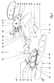
- Figure 1 is a display instrument according to the invention with a front frame 2, a printed circuit board 9 and a rear wall 10 before assembly.
- a cover plate 1 can be clipped into the front of the front frame 2.
- Printed circuit board 9 On the Printed circuit board 9 are several measuring units 11, control lights 19 and incandescent lamps 20 arranged.
- the measuring units 11 are used to drive the assembled state the display instrument via a dial 6 swiveling pointers 12.
- the dial 6 is made of a translucent material and Attachment to a light guide plate 8 that can be illuminated by the incandescent lamps 20 intended.
- the measuring mechanisms 11 form with the hands 12 and the dial 6 one display unit each, combined with other display units form the display instrument, also known as a combination instrument.
- Such combination instruments are preferred in motor vehicles used and are usually built into the instrument panel there.
- the front frame 2 has several recesses 13 for the display units and is formed in one piece with light wells 15 for the indicator lights 19.
- the front of the front frame 2 is used to attach a panel 7.
- This Aperture 7 has corresponding recesses 13 in the front frame 2 Recesses 14 for the display units and hidden in the assembled Condition of the light wells 15.
- the front frame 2 has several Holding parts 17 for fastening the combination instrument in the instrument panel of the motor vehicle on An electrical connection of the combination instrument with the vehicle electronics takes place by means of the printed circuit board 9 arranged plug contacts.
- the dial 6 and the light guide plate 8 each have a recess 22 for a flat screen to be arranged on the printed circuit board 9
- Printed circuit board 9 is an incandescent lamp 21 for illuminating the flat screen 26 intended.
- the light guide plate 8 has a further recess 16, through which is additional information from a row on the circuit board 9 arranged LEDs 18 on the dial 6. Therefor required light wells 35 are provided for mounting on the printed circuit board 9.
- a recess in the front frame 2 and the cover plate 1 25 is used to carry out an operating element 23 for resetting of a trip meter.
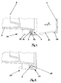
- FIGs 2 3 a section of the edge region of a front frame 2 and one Cover plate 1 is shown enlarged in an alternative embodiment, where to illustrate the position of the section, a level 5, in which a Dial is to be arranged, and a recess 13 of the front frame 2 for a display unit is located.
- Figure 2 shows the two components before they in the drawn joining direction A, which is approximately the axial direction B of the display instrument (Fig. 1) corresponds to be composed.
- the assembled one Condition is shown in Figure 3. It can be seen that in the area of Circumference 27 of the front frame 2 an axial recess facing the cover plate 1 4 is arranged.
- axial recess 4 in the region of the circumference 27 of the front frame 2 around this continuously revolving axial recess 4 is a an approximately U-shaped cross section having an elastic spacer 3 inserted.
- the axial recess 4 is groove-shaped and the spacer 3 lies directly on its groove base 33 and the groove flanks 24, 36.
- a web 28 running around the circumference of the cover disk 1 is can be engaged in the spacer 3.
- a same section of a peripheral region of a front frame 2 and 4, 5 shows a cover plate 1 in an embodiment corresponding to FIG. 1.
- a dial level 5 drawn in the area of the circumference 27 of the front frame 2 .
- the groove base 33 one away from the cover plate 1 has indentation 34, as a spacer 3 is a polyester foam injected, which hardens after the spraying process and in an elastic State remains.
- Clip tabs 30 take correspondingly attached to the circumference of the cover plate 1 Clip 29 on.
Landscapes
- Engineering & Computer Science (AREA)
- Chemical & Material Sciences (AREA)
- Combustion & Propulsion (AREA)
- Transportation (AREA)
- Mechanical Engineering (AREA)
- Instrument Panels (AREA)
- Connection Of Plates (AREA)
Abstract
Description
- Fig. 1
- ein Anzeigeinstrument in einer Explosionsdarstellung,
- Fig. 2, 3
- einen Ausschnitt eines Frontrahmens und einer Deckscheibe in einer ersten Ausführungsform und
- Fig. 4, 5
- einen Ausschnitt eines Frontrahmens und einer Deckscheibe in einer zweiten Ausführungsform.
Claims (19)
- Anzeigeinstrument, insbesondere für ein Kraftfahrzeug, mit einem Gehäuse mit einem eine Deckscheibe halternden Frontrahmen und einem zwischen Deckscheibe und Frontrahmen angeordneten elastischen Abstandselement, dadurch gekennzeichnet, daß das Abstandselement (3) in einer im Bereich des Umfangs (27) des Frontrahmens (2) angeordneten und der Deckscheibe (1) zugewandten Axialausnehmung (4) plaziert ist, in die die Deckscheibe (1) eingreifbar ist.
- Anzeigeinstrument nach Anspruch 1, dadurch gekennzeichnet, daß die Axialausnehmung (4) im Bereich des Umfangs (27) des Frontrahmens (2) um diesen kontinuierlich umläuft.
- Anzeigeinstrument nach Anspruch 1 oder 2, dadurch gekennzeichnet, daß die Axialausnehmung (4) einen nutförmigen Querschnitt aufweist.
- Anzeigeinstrument nach Anspruch 3, dadurch gekennzeichnet, daß der Nutgrund (33) der Axialausnehmung (4) eine von der Deckscheibe (1) weg weisende Einbuchtung (34) aufweist.
- Anzeigeinstrument nach einem der vorhergehenden Ansprüche, dadurch gekennzeichnet, daß das Abstandselement (3) aus einem aushärtenden Werkstoff besteht.
- Anzeigeinstrument nach einem der vorhergehenden Ansprüche, dadurch gekennzeichnet, daß das Abstandselement (3) einen Klebstoff aufweist.
- Anzeigeinstrument nach einem der vorhergehenden Ansprüche, dadurch gekennzeichnet, daß das Abstandselement (3) aus einem Polyesterschaum besteht.
- Anzeigeinstrument nach einem der vorhergehenden Ansprüche, dadurch gekennzeichnet, daß das Abstandselement (3) zwischen Frontrahmen (2) und Deckscheibe (1) einklemmbar ist.
- Anzeigeinstrument nach einem der vorhergehenden Ansprüche, dadurch gekennzeichnet, daß der Frontrahmen (2) und die Deckscheibe (3) mittels einer Klipsvorrichtung (31) miteinander verbindbar sind.
- Anzeigeinstrument nach Anspruch 9, dadurch gekennzeichnet, daß im Bereich des Umfangs (32) der Deckscheibe (1) mit Abstand zueinander mindestens zwei Klipse (29) angeordnet sind, die in korrespondierende, am Frontrahmen (2) angeordnete Klipslaschen (30) eingreifbar sind.
- Anzeigeinstrument nach Anspruch 10, dadurch gekennzeichnet, daß das Abstandselement (3) Einbuchtungen oder Ausnehmungen aufweist, durch die die Klipse (29) hindurchgreifbar sind.
- Anzeigeinstrument nach einem der vorhergehenden Ansprüche, dadurch gekennzeichnet, daß die Deckscheibe (1) im Bereich ihres Umfangs (32) einen in etwa in Axialrichtung (B) des Anzeigeinstruments zu dem Frontrahmen (2) weisenden Steg (28) aufweist.
- Anzeigeinstrument nach Anspruch 12, dadurch gekennzeichnet, daß der Steg (28) an das Abstandselement (3) anlegbar ist.
- Anzeigeinstrument nach Anspruch 13, dadurch gekennzeichnet, daß der Steg (28) in das Abstandselement (3) eingreifbar ist.
- Anzeigeinstrument nach einem der vorhergehenden Ansprüche, dadurch gekennzeichnet, daß der Frontrahmen (2) aus einem Polypropylen (PP) und die Deckscheibe (1) aus einem Polymethylmethacrylat (PMMA) aufweisenden Werkstoff besteht.
- Verfahren zum Verbinden einer Deckscheibe mit einem Frontrahmen eines Anzeigeinstrumentes nach einem der vorhergehenden Ansprüche, dadurch gekennzeichnet, daß in einem ersten Schrift das Abstandselement (3) in die Axialausnehmung (4) des Frontrahmens (2) eingebracht wird und daß in einem zweiten Schrift die Deckscheibe (1) in die Axialausnehmung (4) gegen das Abstandselement (3) eingedrückt wird.
- Verfahren nach Anspruch 16, dadurch gekennzeichnet, daß das Abstandselement (3) aus einem beim Einbringen in die Axialausnehmung (4) fließfähigen Werkstoff besteht und in die Axialausnehmung (4) eingespritzt wird.
- Verfahren nach einem der Ansprüche 16 oder 17, dadurch gekennzeichnet, daß das Abstandselement (3) nach dem Zusammenfügen von Frontrahmen (2) und Deckscheibe (1) aushärtet.
- Verfahren nach einem der Ansprüche 16 bis 18, dadurch gekennzeichnet, daß der Frontrahmen (2) und die Deckscheibe (1) miteinander verklipst werden.
Applications Claiming Priority (2)
| Application Number | Priority Date | Filing Date | Title |
|---|---|---|---|
| DE19859919A DE19859919A1 (de) | 1998-12-23 | 1998-12-23 | Anzeigeinstrument |
| DE19859919 | 1998-12-23 |
Publications (3)
| Publication Number | Publication Date |
|---|---|
| EP1013496A2 true EP1013496A2 (de) | 2000-06-28 |
| EP1013496A3 EP1013496A3 (de) | 2001-05-16 |
| EP1013496B1 EP1013496B1 (de) | 2006-03-01 |
Family
ID=7892572
Family Applications (1)
| Application Number | Title | Priority Date | Filing Date |
|---|---|---|---|
| EP99124706A Expired - Lifetime EP1013496B1 (de) | 1998-12-23 | 1999-12-11 | Anzeigeinstrument |
Country Status (4)
| Country | Link |
|---|---|
| US (2) | US6476320B1 (de) |
| EP (1) | EP1013496B1 (de) |
| DE (2) | DE19859919A1 (de) |
| ES (1) | ES2257839T3 (de) |
Cited By (7)
| Publication number | Priority date | Publication date | Assignee | Title |
|---|---|---|---|---|
| EP1382478A1 (de) * | 2002-07-18 | 2004-01-21 | Dr.Ing. h.c.F. Porsche Aktiengesellschaft | Anzeigeinstrument mit einem Gehäuse |
| EP2612780A1 (de) * | 2012-01-07 | 2013-07-10 | Johnson Controls Automotive Electronics SAS | Verfahren zur Montage einer Anzeigevorrichtung und Anzeigevorrichtung |
| EP3045341A1 (de) * | 2015-01-16 | 2016-07-20 | Yazaki North America, Inc. | Anzeigeinstrument in ring |
| EP3045342A1 (de) * | 2015-01-16 | 2016-07-20 | Yazaki North America, Inc. | Neukonfigurierbare messvorrichtung über anzeige |
| DE102011054151B4 (de) * | 2010-10-08 | 2017-05-04 | Visteon Global Technologies, Inc. | Anzeigesystem mit ultradünnem lichtleiter für eine gebündelte instrumentenbeleuchtung |
| EP3581422A1 (de) * | 2018-06-14 | 2019-12-18 | Aptiv Technologies Limited | Armaturentafelbaugruppe |
| EP3756927A1 (de) * | 2019-06-27 | 2020-12-30 | Marelli Stuttgart (Germany) GmbH | Rahmen eines kombiinstruments eines kraftfahrzeugs und kombiinstrument mit einem solchen rahmen |
Families Citing this family (24)
| Publication number | Priority date | Publication date | Assignee | Title |
|---|---|---|---|---|
| DE19859919A1 (de) * | 1998-12-23 | 2000-07-06 | Mannesmann Vdo Ag | Anzeigeinstrument |
| WO2001075981A1 (en) * | 2000-04-04 | 2001-10-11 | Matsushita Electric Industrial Co.,Ltd. | Thin-film semiconductor device and method for manufacturing the same |
| FR2857744B1 (fr) * | 2003-07-16 | 2005-10-28 | Johnson Contr Automotive Elect | Aiguille d'indicateur de bord a eclairage luminescent |
| US7105741B2 (en) * | 2004-07-16 | 2006-09-12 | Spx Corporation | Vehicle diagnostic device housing assembly and method positioned and retained in vehicle cup holder |
| US7885739B2 (en) * | 2004-08-19 | 2011-02-08 | Spx Corporation | Open-ended vehicle diagnostic device interface |
| US7805228B2 (en) * | 2004-08-19 | 2010-09-28 | Spx Corporation | Vehicle diagnostic device |
| US7430465B2 (en) | 2004-11-17 | 2008-09-30 | Spx Corporation | Open-ended PC host interface for vehicle data recorder |
| US7100959B1 (en) * | 2006-01-06 | 2006-09-05 | Nu Image Components, Inc. | Molded dashboard cover |
| DE102007002501B4 (de) * | 2007-01-17 | 2011-12-15 | Bayerische Motoren Werke Aktiengesellschaft | Anordnung einer Vorrichtung in einem Bauteil einer Innenausstattung eines Kraftfahrzeuges |
| US7753423B2 (en) * | 2008-01-08 | 2010-07-13 | Toyota Motor Engineering & Manufacturing North America, Inc. | Component assembly for a motor vehicle |
| US8340855B2 (en) | 2008-04-22 | 2012-12-25 | Spx Corporation | USB isolation for vehicle communication interface |
| JP5200857B2 (ja) * | 2008-10-28 | 2013-06-05 | 住友電装株式会社 | 電気接続箱 |
| US8138901B2 (en) | 2009-02-24 | 2012-03-20 | Visteon Global Technologies, Inc. | Instrument cluster mask with tell-tales |
| WO2012018733A2 (en) | 2010-08-03 | 2012-02-09 | Spx Corporation | Vehicle diagnostic, communication and signal delivery system |
| FR2970909B1 (fr) * | 2011-01-31 | 2016-02-05 | Johnson Controls Tech Co | Tableau de bord |
| US8678466B2 (en) * | 2012-03-30 | 2014-03-25 | Toyota Motor Engineering & Manufacturing North America, Inc. | Instrument panel assembly |
| DE102012018259A1 (de) * | 2012-09-17 | 2014-03-20 | GM Global Technology Operations, LLC (n.d. Ges. d. Staates Delaware) | Scheibeneinheit, Blendeneinheit, Anzeigeninstrument, Anzeigeneinrichtung, Kraftfahrzeug und Verfahren hierzu |
| US20180201712A1 (en) * | 2015-07-16 | 2018-07-19 | Basf Se | Hot-melt adhesive, containing poly(meth) acrylate made from alkyl(meth)acrylates and from determined heterocyclic groups containing (meth)acrylates |
| DE102015010295A1 (de) | 2015-08-07 | 2017-02-09 | Audi Ag | Anzeigevorrichtung für ein Kraftfahrzeug |
| US9981556B2 (en) * | 2015-12-01 | 2018-05-29 | Continental Automotive Systems, Inc. | Mold and fold vehicle display assembly |
| US10654527B2 (en) * | 2016-04-07 | 2020-05-19 | Continental Automotive Systems, Inc | Integrated fastener for instrumentation cluster |
| US10363819B2 (en) | 2017-10-05 | 2019-07-30 | Toyota Motor Engineering & Manufacturing North America, Inc. | Meter cluster assembly |
| TWM561976U (zh) * | 2017-12-08 | 2018-06-11 | 和碩聯合科技股份有限公司 | 機殼結構 |
| DE202020100955U1 (de) * | 2020-02-21 | 2021-05-25 | ZF Automotive Safety Germany GmbH | Lenkradbaugruppe sowie Abdeckelement für eine solche Lenkradbaugruppe |
Family Cites Families (25)
| Publication number | Priority date | Publication date | Assignee | Title |
|---|---|---|---|---|
| FR937683A (fr) * | 1943-10-09 | 1948-08-24 | Bendix Aviat Corp | Dispositif de fermeture étanche en particulier pour instruments |
| DE2515830A1 (de) * | 1975-04-11 | 1976-10-21 | Moto Meter Gmbh | Frontscheibenabdichtung |
| DE7727618U1 (de) * | 1977-09-07 | 1978-02-02 | Gulbinat, Ewald, 6942 Moerlenbach | Einrichtung zur loesbaren befestigung einer abdeckscheibe an gehaeusen fuer temperatur- und druckmessgeraete o.dgl. |
| DE3101519C2 (de) * | 1981-01-19 | 1986-07-10 | Licentia Patent-Verwaltungs-Gmbh, 6000 Frankfurt | Elektrisch leitendes Dichtungsprofil zur Herstellung einer Hochfrequenz-Dichtung zwischen metallischen Gehäuseteilen |
| US4560083A (en) * | 1984-01-16 | 1985-12-24 | Trw Inc. | Closure and method for an aperture |
| US4874906A (en) * | 1987-06-29 | 1989-10-17 | Shotey Michael J | Plug enclosing outlet cover |
| US4939934A (en) * | 1989-01-18 | 1990-07-10 | Vdo Adolf Schindling Ag | Combination instrument |
| DE3903229A1 (de) * | 1989-02-03 | 1990-08-09 | Vdo Schindling | Elektronischer schaltkreis |
| DE4227579C2 (de) * | 1992-08-20 | 2001-02-01 | Mannesmann Vdo Ag | Anzeigegerät |
| DE4315027A1 (de) * | 1992-12-02 | 1994-06-09 | Vdo Schindling | Kombinations-Instrument |
| JP2574258Y2 (ja) * | 1993-02-12 | 1998-06-11 | 住友電装株式会社 | 防水筺体 |
| JPH079018U (ja) * | 1993-06-25 | 1995-02-07 | 住友電装株式会社 | 分岐接続箱 |
| DE4332716A1 (de) * | 1993-09-25 | 1995-03-30 | Vdo Schindling | Kombinations-Instrument |
| JPH07286866A (ja) * | 1994-04-18 | 1995-10-31 | Yazaki Corp | メータケース前面板への透明板の取付構造 |
| JP3006654B2 (ja) * | 1994-05-19 | 2000-02-07 | 矢崎総業株式会社 | メータモジュール組立体 |
| JP2891324B2 (ja) * | 1994-05-25 | 1999-05-17 | 矢崎総業株式会社 | 電気接続箱の防水シール構造 |
| CH689321A5 (de) * | 1994-11-04 | 1999-02-15 | Gec Alsthom T & D Ag | Sichtfenster. |
| US5703612A (en) * | 1995-01-20 | 1997-12-30 | Nu-Tech & Engineering, Inc. | Illuminated pointer for an analog gauge and related method of use and manufacture |
| FR2742404B1 (fr) * | 1995-12-19 | 1998-02-20 | Reydel Sa | Tableau de bord |
| JP3446483B2 (ja) * | 1996-07-03 | 2003-09-16 | 住友電装株式会社 | 電気接続箱 |
| TW337401U (en) * | 1997-10-09 | 1998-07-21 | Weltek Electronics Co Ltd | Waterproof case |
| US6179429B1 (en) * | 1998-04-13 | 2001-01-30 | Visteon Global Technologies, Inc. | Illuminated instrument cluster dial for an automotive vehicle |
| JP3624720B2 (ja) * | 1998-10-29 | 2005-03-02 | 住友電装株式会社 | 太陽電池モジュール用端子ボックス装置 |
| DE19859919A1 (de) * | 1998-12-23 | 2000-07-06 | Mannesmann Vdo Ag | Anzeigeinstrument |
| JP2001326475A (ja) * | 2000-05-15 | 2001-11-22 | Nec Corp | 通信機器の防水構造 |
-
1998
- 1998-12-23 DE DE19859919A patent/DE19859919A1/de not_active Ceased
-
1999
- 1999-12-11 ES ES99124706T patent/ES2257839T3/es not_active Expired - Lifetime
- 1999-12-11 DE DE59913167T patent/DE59913167D1/de not_active Expired - Lifetime
- 1999-12-11 EP EP99124706A patent/EP1013496B1/de not_active Expired - Lifetime
- 1999-12-22 US US09/470,190 patent/US6476320B1/en not_active Expired - Lifetime
-
2002
- 2002-09-05 US US10/236,897 patent/US6653567B2/en not_active Expired - Lifetime
Non-Patent Citations (1)
| Title |
|---|
| None |
Cited By (9)
| Publication number | Priority date | Publication date | Assignee | Title |
|---|---|---|---|---|
| EP1382478A1 (de) * | 2002-07-18 | 2004-01-21 | Dr.Ing. h.c.F. Porsche Aktiengesellschaft | Anzeigeinstrument mit einem Gehäuse |
| US6846031B2 (en) | 2002-07-18 | 2005-01-25 | Dr. Ing H.C.F. Porsche Aktiengesellschaft | Indicating instrument assembly having a housing and method of making same |
| DE102011054151B4 (de) * | 2010-10-08 | 2017-05-04 | Visteon Global Technologies, Inc. | Anzeigesystem mit ultradünnem lichtleiter für eine gebündelte instrumentenbeleuchtung |
| EP2612780A1 (de) * | 2012-01-07 | 2013-07-10 | Johnson Controls Automotive Electronics SAS | Verfahren zur Montage einer Anzeigevorrichtung und Anzeigevorrichtung |
| WO2013102678A1 (en) * | 2012-01-07 | 2013-07-11 | Johnson Controls Automotive Electronics Sas | Method for assembling a display device and display device |
| EP3045341A1 (de) * | 2015-01-16 | 2016-07-20 | Yazaki North America, Inc. | Anzeigeinstrument in ring |
| EP3045342A1 (de) * | 2015-01-16 | 2016-07-20 | Yazaki North America, Inc. | Neukonfigurierbare messvorrichtung über anzeige |
| EP3581422A1 (de) * | 2018-06-14 | 2019-12-18 | Aptiv Technologies Limited | Armaturentafelbaugruppe |
| EP3756927A1 (de) * | 2019-06-27 | 2020-12-30 | Marelli Stuttgart (Germany) GmbH | Rahmen eines kombiinstruments eines kraftfahrzeugs und kombiinstrument mit einem solchen rahmen |
Also Published As
| Publication number | Publication date |
|---|---|
| ES2257839T3 (es) | 2006-08-01 |
| DE59913167D1 (de) | 2006-04-27 |
| US20030015364A1 (en) | 2003-01-23 |
| DE19859919A1 (de) | 2000-07-06 |
| EP1013496A3 (de) | 2001-05-16 |
| EP1013496B1 (de) | 2006-03-01 |
| US6476320B1 (en) | 2002-11-05 |
| US6653567B2 (en) | 2003-11-25 |
Similar Documents
| Publication | Publication Date | Title |
|---|---|---|
| EP1013496B1 (de) | Anzeigeinstrument | |
| EP0915772B1 (de) | Kombinationsinstrument | |
| DE10259194B4 (de) | Automobil-Armaturentafelbaugruppe | |
| DE102004029248B4 (de) | Beleuchtungssystem für Anzeigen, insbesondere in Fahrzeugen sowie Abdeckungsbauteil für derartiges Beleuchtungssystem | |
| DE19755497C1 (de) | Steuergerätegehäuse aus Kunststoff für ein Kraftfahrzeug | |
| DE102006039065A1 (de) | Befestigungsvorrichtung für einen optischen Sensor an einer Fahrzeugscheibe | |
| EP1072383A1 (de) | Mehrkomponenten-Kunststoffspritzgussteil mit optischer Anzeigefunktion | |
| WO2005009795A2 (de) | Dekor-zierteil | |
| EP0378739A2 (de) | Kombinationsinstrument | |
| DE102012018259A1 (de) | Scheibeneinheit, Blendeneinheit, Anzeigeninstrument, Anzeigeneinrichtung, Kraftfahrzeug und Verfahren hierzu | |
| DE112006002444T5 (de) | Betriebswahlschalter | |
| DE19652139C1 (de) | Anzeigeeinheit | |
| DE3232258A1 (de) | Umhuellung fuer messinstrumente, insbesondere manometer | |
| DE10160749A1 (de) | Anzeigevorrichtung mit mindestens einem in deren frontseitigem Gehäuseteil angeordneten Zeigerinstrument | |
| DE19835215A1 (de) | Kombinationsinstrument | |
| DE19947437A1 (de) | Sensor | |
| DE10105362B4 (de) | Gehäuse, insbesondere für eine Anzeigevorrichtung | |
| DE4343201A1 (de) | Anzeigeeinrichtung | |
| DE19934446A1 (de) | Anzeigeinstrument | |
| DE19740424A1 (de) | Anzeigeeinheit mit einer Flüssigkristallzelle | |
| WO2000022321A2 (de) | Schaltvorrichtung für ein automatikgetriebe | |
| DE19654415A1 (de) | Armaturentafel, insbesondere für ein Fahrzeug | |
| DE10333978A1 (de) | Optoelektronische Sensoreinrichtung | |
| DE19747289B4 (de) | Verfahren zur Leiterplattenmontage eines Schrittmotors | |
| DE102022127236A1 (de) | Kameraanordnung mit an einem Gehäuseelement festgelegter und an einer Linsenvorrichtung anliegender Abdeckeinrichtung und Verfahren zum Fertigen einer solchen Kameraanordnung |
Legal Events
| Date | Code | Title | Description |
|---|---|---|---|
| PUAI | Public reference made under article 153(3) epc to a published international application that has entered the european phase |
Free format text: ORIGINAL CODE: 0009012 |
|
| AK | Designated contracting states |
Kind code of ref document: A2 Designated state(s): DE ES FR GB |
|
| AX | Request for extension of the european patent |
Free format text: AL;LT;LV;MK;RO;SI |
|
| PUAL | Search report despatched |
Free format text: ORIGINAL CODE: 0009013 |
|
| AK | Designated contracting states |
Kind code of ref document: A3 Designated state(s): AT BE CH CY DE DK ES FI FR GB GR IE IT LI LU MC NL PT SE |
|
| AX | Request for extension of the european patent |
Free format text: AL;LT;LV;MK;RO;SI |
|
| RAP1 | Party data changed (applicant data changed or rights of an application transferred) |
Owner name: SIEMENS AKTIENGESELLSCHAFT |
|
| AKX | Designation fees paid |
Free format text: DE ES FR GB |
|
| 17P | Request for examination filed |
Effective date: 20011119 |
|
| 17Q | First examination report despatched |
Effective date: 20040416 |
|
| GRAP | Despatch of communication of intention to grant a patent |
Free format text: ORIGINAL CODE: EPIDOSNIGR1 |
|
| GRAS | Grant fee paid |
Free format text: ORIGINAL CODE: EPIDOSNIGR3 |
|
| GRAA | (expected) grant |
Free format text: ORIGINAL CODE: 0009210 |
|
| AK | Designated contracting states |
Kind code of ref document: B1 Designated state(s): DE ES FR GB |
|
| REG | Reference to a national code |
Ref country code: GB Ref legal event code: FG4D Free format text: NOT ENGLISH |
|
| REF | Corresponds to: |
Ref document number: 59913167 Country of ref document: DE Date of ref document: 20060427 Kind code of ref document: P |
|
| GBT | Gb: translation of ep patent filed (gb section 77(6)(a)/1977) |
Effective date: 20060412 |
|
| REG | Reference to a national code |
Ref country code: ES Ref legal event code: FG2A Ref document number: 2257839 Country of ref document: ES Kind code of ref document: T3 |
|
| ET | Fr: translation filed | ||
| PLBE | No opposition filed within time limit |
Free format text: ORIGINAL CODE: 0009261 |
|
| STAA | Information on the status of an ep patent application or granted ep patent |
Free format text: STATUS: NO OPPOSITION FILED WITHIN TIME LIMIT |
|
| 26N | No opposition filed |
Effective date: 20061204 |
|
| REG | Reference to a national code |
Ref country code: ES Ref legal event code: PC2A Owner name: CONTINENTAL AUTOMOTIVE GMBH Effective date: 20110325 |
|
| REG | Reference to a national code |
Ref country code: FR Ref legal event code: TP |
|
| REG | Reference to a national code |
Ref country code: GB Ref legal event code: 732E Free format text: REGISTERED BETWEEN 20110825 AND 20110831 |
|
| PGFP | Annual fee paid to national office [announced via postgrant information from national office to epo] |
Ref country code: GB Payment date: 20141219 Year of fee payment: 16 Ref country code: ES Payment date: 20141226 Year of fee payment: 16 |
|
| REG | Reference to a national code |
Ref country code: DE Ref legal event code: R084 Ref document number: 59913167 Country of ref document: DE |
|
| REG | Reference to a national code |
Ref country code: FR Ref legal event code: PLFP Year of fee payment: 17 |
|
| GBPC | Gb: european patent ceased through non-payment of renewal fee |
Effective date: 20151211 |
|
| PG25 | Lapsed in a contracting state [announced via postgrant information from national office to epo] |
Ref country code: GB Free format text: LAPSE BECAUSE OF NON-PAYMENT OF DUE FEES Effective date: 20151211 |
|
| REG | Reference to a national code |
Ref country code: FR Ref legal event code: PLFP Year of fee payment: 18 |
|
| REG | Reference to a national code |
Ref country code: ES Ref legal event code: FD2A Effective date: 20170306 |
|
| PG25 | Lapsed in a contracting state [announced via postgrant information from national office to epo] |
Ref country code: ES Free format text: LAPSE BECAUSE OF NON-PAYMENT OF DUE FEES Effective date: 20151212 |
|
| REG | Reference to a national code |
Ref country code: FR Ref legal event code: PLFP Year of fee payment: 19 |
|
| PGFP | Annual fee paid to national office [announced via postgrant information from national office to epo] |
Ref country code: FR Payment date: 20181219 Year of fee payment: 20 |
|
| PGFP | Annual fee paid to national office [announced via postgrant information from national office to epo] |
Ref country code: DE Payment date: 20181231 Year of fee payment: 20 |
|
| REG | Reference to a national code |
Ref country code: DE Ref legal event code: R071 Ref document number: 59913167 Country of ref document: DE |