EP1013532B1 - Appareil de déplacement, aménagé pour guider un dispositif de support le long d'au moins deux rails, et méthode correspondante - Google Patents
Appareil de déplacement, aménagé pour guider un dispositif de support le long d'au moins deux rails, et méthode correspondante Download PDFInfo
- Publication number
- EP1013532B1 EP1013532B1 EP99204460A EP99204460A EP1013532B1 EP 1013532 B1 EP1013532 B1 EP 1013532B1 EP 99204460 A EP99204460 A EP 99204460A EP 99204460 A EP99204460 A EP 99204460A EP 1013532 B1 EP1013532 B1 EP 1013532B1
- Authority
- EP
- European Patent Office
- Prior art keywords
- motors
- rails
- controlled
- rail
- control means
- Prior art date
- Legal status (The legal status is an assumption and is not a legal conclusion. Google has not performed a legal analysis and makes no representation as to the accuracy of the status listed.)
- Expired - Lifetime
Links
- 238000006073 displacement reaction Methods 0.000 title claims abstract description 45
- 238000000034 method Methods 0.000 title claims description 13
- 230000008901 benefit Effects 0.000 description 11
- 238000010276 construction Methods 0.000 description 5
- 230000009467 reduction Effects 0.000 description 5
- 239000011324 bead Substances 0.000 description 4
- 238000004519 manufacturing process Methods 0.000 description 4
- 239000000725 suspension Substances 0.000 description 4
- 230000008878 coupling Effects 0.000 description 3
- 238000010168 coupling process Methods 0.000 description 3
- 238000005859 coupling reaction Methods 0.000 description 3
- 230000007257 malfunction Effects 0.000 description 3
- 230000008859 change Effects 0.000 description 2
- 230000001419 dependent effect Effects 0.000 description 2
- 238000012423 maintenance Methods 0.000 description 2
- 230000003068 static effect Effects 0.000 description 2
- 238000005452 bending Methods 0.000 description 1
- 230000001684 chronic effect Effects 0.000 description 1
- 238000010586 diagram Methods 0.000 description 1
- 230000000694 effects Effects 0.000 description 1
- 230000005484 gravity Effects 0.000 description 1
- 238000009434 installation Methods 0.000 description 1
- 230000007246 mechanism Effects 0.000 description 1
- 230000001360 synchronised effect Effects 0.000 description 1
- 230000002123 temporal effect Effects 0.000 description 1
Images

Classifications
-
- B—PERFORMING OPERATIONS; TRANSPORTING
- B61—RAILWAYS
- B61B—RAILWAY SYSTEMS; EQUIPMENT THEREFOR NOT OTHERWISE PROVIDED FOR
- B61B5/00—Elevated railway systems without suspended vehicles
- B61B5/02—Elevated railway systems without suspended vehicles with two or more rails
-
- B—PERFORMING OPERATIONS; TRANSPORTING
- B66—HOISTING; LIFTING; HAULING
- B66B—ELEVATORS; ESCALATORS OR MOVING WALKWAYS
- B66B9/00—Kinds or types of lifts in, or associated with, buildings or other structures
- B66B9/06—Kinds or types of lifts in, or associated with, buildings or other structures inclined, e.g. serving blast furnaces
- B66B9/08—Kinds or types of lifts in, or associated with, buildings or other structures inclined, e.g. serving blast furnaces associated with stairways, e.g. for transporting disabled persons
- B66B9/0838—Levelling gears
Definitions
- This invention relates to a displacement apparatus arranged for guiding a carrying device along at least two rails and to a method for controlling such an apparatus.
- a displacement apparatus is known from European patent application 0,394,201.
- This known displacement apparatus comprises a first and a second rail, arranged above each other in one plane, while on each rail a running gear is arranged which carry a carrying device.
- Each running gear comprises a toothed wheel engaging a tooth track on the rail in question.
- This displacement apparatus comprises a motor providing for the drive of the carrying device, with the position of the carrying device, at least in inclined portions of the rails, being determined by the toothed wheels and the motor.
- the upper rail, at least in horizontal portions, is provided with a stability rail which is guided between two pairs of stability wheels, which stability wheels are fixedly connected with the carrying device. It is thus provided that upon a load off the center of the carrying device, as seen in front view, the carrying device is yet held in the desired vertical position.
- This known displacement apparatus involves the disadvantage that it is particularly costly in manufacture and use, while moreover there is a substantial risk of malfunctions, in particular in that the displacement apparatus, in the horizontal portions of the rails is statically overdetermined.
- This displacement apparatus too is costly in manufacture and maintenance, and moreover susceptible to failure.
- this is also because upon asymmetrical loading of the carrying device, at least to the extent that a moment relative to the running gears arises, an unequal loading of the two driving wheels is obtained, so that an increased wear will arise and moreover the disadvantages mentioned are enhanced still further.
- EP 0,152,136 discloses a displacement apparatus of the type described in the opening paragraph hereof, in which the two rails are mutually connected by connecting parts and are of hollow design. Through the rails and the connecting parts extends an endless bead chain. On each rail a running gear is provided, mutually connected by a carrying device. The upper rail is open at the underside, such that the upper running gear, by way of a driving cam, can engage between the beads of the chain. Adjacent the lower end of the upper rail, a driving wheel is arranged with which the bead chain can be moved, thereby driving the carrying device through the driving cam.
- Each running gear comprises two sets of wheels engaging the same rail at spaced apart points, the sets of wheels running on the upper and the lower rails being mutually coupled through a four-bar mechanism, such that positional changes occur synchronously.
- This known displacement apparatus is complex in construction and control and is susceptible to wear, in particular the bead chain and the driving cam, while the displacement apparatus is moreover statically overdetermined, owing to the four coupled sets of wheels.
- the known displacement apparatuses are suitable for use both with horizontal displacements and with displacements proceeding along an inclined path.
- the object of the invention is to provide a displacement apparatus of the type described in the opening paragraph hereof, in which the disadvantages mentioned of the known displacement apparatuses are avoided while maintaining the advantages thereof.
- a displacement apparatus according to the invention is characterized by the features according to claim 1.
- a displacement apparatus according to the invention is characterized by the features according to claim 2.
- position-controlled motors on rails extending horizontally, at least inclining to a very minor extent only provides the advantage that a carrying device can be simply held in a desired position by means of the driving gears, regardless of the loading of the carrying device, while the rails and driving gears can be manufactured with relatively large tolerances.
- Force-controlled drive of the motors on inclined parts of the rails then provides the advantage that the construction is not statically overdetermined, and on the inclined parts is automatically held in the desired position.
- each motor will be controlled depending on the forces applied to the driving gear, which forces are directly dependent on the loading of the carrying device.
- the running speed of each of the motors, and hence of each of the running wheels on the inclined rails can be adjusted, such that at all times the desired position of the carrying device is maintained.
- the stability of the carrying device on the inclined portions is substantially obtained in that the running wheels can then easily transmit forces in a direction perpendicular to the longitudinal direction of the respective rails, and by gravity.
- a displacement apparatus is characterized by the features according to claim 4.
- the registration means for determining the angle of inclination of the rails adjacent the driving gears provide the advantage that in a simple manner the moment can be determined at which a switch is to be made from force-controlled drive to position-controlled drive or vice versa.
- the angles of inclination at which a switch is made are preferably chosen such that in each case the carrying device is still just stable.
- a displacement apparatus according to the invention is further characterized by the features according to claim 7.
- the advantage is achieved that the desired stability of the carrying device on the horizontal, at any rate only slightly inclined, rails can be obtained and maintained still better, without additional measures, while on the inclined part of the rails the stability is maintained, while the driving gears can simply follow the inclination and any inaccuracies of the rails.
- the advantage thereby achieved is that in the inclined portion of the rails the two motors can independently of each other be controlled and checked in speed, such that the independent drives can form a so-called "fail-safe" system.
- the invention further relates to a method for controlling a displacement apparatus, characterized by the features according to claim 9.
- the control means at least one reference angle is set, the motors being controlled in a position-controlled manner when the angle of the rails is less than the reference angle, and the motors being controlled in a force-controlled manner when the angle of the rails is greater than the reference angle.
- the motors can be slowed down, such that the carrying device is slowed down and optionally stopped.
- the motors can be made of self-locking design, such that upon failure of either of the two motors, the carrying device automatically comes to a halt.
- the motors can be mutually coupled, in particular in the case of position-controlled drive, while the coupling can be accomplished mechanically, though preferably electronically.
- 'Motor' is herein understood to mean at least a drive unit for actively driving a running wheel in a driving gear, which may or may not be directly and individually energized.
- a displacement apparatus is described as a platform lift but other embodiments are also possible, such as a chairlift or other apparatuses for displacing persons and/or goods in horizontal and/or vertical direction.
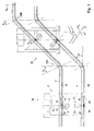
- Fig. 1 shows in front view a portion of a stairlift according to the invention, comprising a first rail 2 and a second rail 4, extending parallel thereto and contained in the same vertical plane, on which two rails 2, 4 a carrying device 6 is carried by a first driving gear 8 engaging the first rail 2 and a second driving gear 10 engaging the second rail 4.
- the first driving gear 8 comprises a first motor 12, which is connected via a reduction gearbox 14 with a driving wheel 16.
- the driving wheel 16 is provided with external teeth which can cooperate with a tooth track 18 on the first rail 2.
- the second driving gear 10 comprises a second motor 20, which is connected via a reduction gearbox 22 with a second driving wheel 24, which engages through its outer teeth a second tooth track 26 on the second rail 4.
- a stairlift according to Fig. 1 comprises a horizontal portion 28 of the rails, which merges via a bend 30 with an inclined portion 32 of the rails.
- the two rails 2, 4 are so designed that the vertical distance between the two tooth tracks 18, 26 is substantially the same throughout the path of the rails.
- the driving gears 8, 10 are placed straight above each other, are made of relatively compact design and have, at least viewed in the longitudinal direction of the rail, a relatively narrow overall width.
- a carrying device 6 can also traverse bends having a relatively small bending radius, located, for instance, in a plane perpendicular to the plane of the drawing of Fig. 1, as schematically represented in perspective at the bottom, right, of Fig. 1.
- the driving gears 8, 10 in the embodiment shown in Figs. 1 and 2 are bearing-mounted for pivotal movement relative to the carrying device 6 about a pivotal axis 34, 36, respectively, which may or may not be virtual.
- the pivotal axes extend perpendicularly to the plane of the drawing, adjacent the axes of the driving wheels 16, 24 in the exemplary embodiment shown. What is thus accomplished is that when the driving wheels 16, 24 traverse the bend 30, pivotal movement of the driving gears 8, 10 will be obtained, equal to temporal angular change of the rail 2, 4, so that the running wheels, in particular the driving wheels 16, 24, continue to run straight on the tooth tracks 18, 26.
- Fig. 1 shows a carrying device 6 both on the horizontal portion 28 and on the inclined portion 32, clearly visualizing the change in position of the two driving gears 8, 10.
- At least one of the driving gears 8, 10 comprises angle measuring means 38, with which the position of the respective driving gear 8, 10 relative to, for instance, the vertical can be determined.
- the angle ⁇ 0 in question is about 0°.
- this angle ⁇ 2 is, for instance, 45°.
- the angle ⁇ 2 obviously depends on the angle of inclination ⁇ of the part in question of the rails 2, 4.
- an angle ⁇ 1 is schematically drawn in.
- the carrying device 6 When the driving gears 8, 10 assume a position which includes this angle ⁇ 1 , the carrying device is still just stable. Further, in the second bend 30b in Fig. 1, an angle ⁇ 4 is drawn in. When the driving gears 8, 10 assume an angular position which includes the angle ⁇ 4 , the carrying device 6 is likewise still just stable. If the carrying device assumes an angle greater than ⁇ 1 or ⁇ 4 , the carrying device 6 is in principle unstable, since the driving gears 8, 10 and the rails 2, 4 in this path are insufficiently capable of taking up eccentric forces exerted on the carrying device 6, so that tilting of the carrying device in the plane of the drawing would be possible if no further measures are taken.
- each driving gear 8, 10 is driven in a position-controlled manner.
- the carrying device can be held in the desired vertical position.
- the relative position of each driving gear 8, 10 relative to the respective rail 2, 4 can then be accurately determined and set, while any occurring eccentric forces can be taken up by cooperation of the tooth track 18, 26 and the driving wheel 16, 24. In such a position, no static overdetermination arises.
- the driving gears 8, 10 include an angle greater than a 1 and a 4 , respectively. It will be possible, upon eccentric loading of the carrying device, for a relatively large portion of the occurring forces to be readily taken up by the running wheels 40 of the carrying device 6 (Fig. 2). In fact, a relatively large component of the occurring resulting force will be at right angles to the longitudinal direction of the respective portion of the rail 2, 4. In the path in question, the driving gears 8, 10 are driven in a force-controlled manner, so that static overdetermination is prevented while yet the desired position of the carrying device 6 is automatically obtained and maintained.
- the force control moreover provides the advantage that when one of the driving gears 8, 10 is subject to heavier loading in that the forces arising thereon are greater than, for instance, on the other driving gear, this will automatically be compensated such that for each driving gear the most suitable driving speed is obtained and maintained. Should either of the driving gears 8, 10 on the inclined part 32 of the rails 2, 4 malfunction or fail, this will be established as a result of the occurring forces and/or the rotary speed of preferably the driving gear that does function, and the carrying device will come to a halt and/or be secured in a position in a controlled manner, or be moved up or down along the rail 2, 4 into a horizontal portion 28. On the inclined portion 32 of the rails 2, 4 the force-controlled driving gears 8, 10 therefore function as a "fail-safe" system. This makes further safety provisions such as brakes, safety grippers and the like basically redundant.
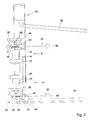
- a carrying device 6, as shown in side elevation in Fig. 2, comprises a backplate 42 on which adjacent the underside a folding platform 46 is mounted by means of a pivotal axis 44.
- the upper driving gear 8 is pivotally connected via the axis 34 and the lower driving gear 10 via the axis 36.
- each driving gear comprises a carrying bracket 48 to which the reduction gearbox 14, 22 with the associated motors 12 and 20, respectively, are connected and in which the driven shafts 50, 52 with the driving wheels 16, 24 are bearing-mounted.
- Each suspension bracket 48 extends around the respective rail 2, 4.
- a slightly frustoconically shaped first guide wheel 54 is arranged, while the suspension bracket 48 carries two second guide wheels 56, which run against the rail 2, in each case staggered about 60° relative to the first guide wheel.
- the rail 2 is confined between the first guide wheel 54 and the two second guide wheels 56.
- two substantially frustoconical third guide wheels 58 are arranged, with the truncated ends facing each other, which third guide wheels lie fittingly against the outer side of the lower rail 4.
- the respective suspension bracket 48 is provided, on the side remote from the third guide wheels 58, with a fourth guide wheel or guide support 60, such that the lower rail 4 is confined between the two third guide wheels 58 and the fourth guide wheel 60.
- the guide wheels 52, 60 each have circumferential surfaces adapted to the outer circumference of the respective rails 2, 4. Such modes of confining rails by guide wheels or the like are well known.
- an angle sensor 38 is coupled for determining the angle taken by the respective driving gear 8, 10.
- a pivoting arm is arranged in the form of a safety bracket 62.
- Fig. 3 it is schematically shown how the driving gears 8, 10 are connected to a central control unit 71.
- the driving gears and connections are made of mirror-symmetrical design, but it is also possible to provide measuring and control means to be described hereinafter for only a single driving gear 8 or 10.
- an angle measuring device 38 is provided, as well as speed measuring and control means 70, and position measuring and control means 72, while moreover means 74 can be provided for registering the loading of the motors 12, 20.
- the different measuring and control means 38, 70, 72, 74 are connected with the central control unit 71, to which moreover operating means 76 are connected.
- These operating means 76 can, for instance, be arranged on the carrying device 6 and/or adjacent an end or an intermediate position of the rails 2, 4. Further connected to the central control unit is a computer 78 or a like data inputting device, with which limit values can be set and with which a part of the control can be programmed, checked and controlled. For that purpose, incidentally, means may also be provided in the central control unit 71, for instance a microprocessor and a keyboard.
- the limit values ⁇ 1 and ⁇ 4 can be inputted in the central control unit, while moreover maximum allowable deviations can be set for the driving gears 8, 10 relative to each other and/or the limit values set. Subsequently, if the angles ⁇ 1 and ⁇ 4 are exceeded, the central unit 71 will switch from position-controlled control to force-controlled control of the motors, or vice versa, based on the conditions mentioned earlier.
- the desired data can be supplied to the central control unit, on the basis of which through control of the driving gears the desired position of the carrying device 6 relative to the rails 2, 4 can be controlled, independently of or depending on the loading thereof.
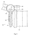
- a driving gear 108 for a carrying device comprises a driving wheel 116, rotatable around a driving shaft 134, which is driven by a first motor 112 with a first reduction gearbox 114.
- the driving wheel 116 extends in a vertical plane, under the upper rail 102, in which a suitable toothing 118 is provided. Owing to the vertical position of the driving wheel 116 in question, the first motor 112 can be fixedly connected with the carrying device 106.
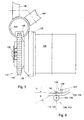
- Fig. 5 shows in a similar view a lower driving gear 110, provided with a second driving wheel 124, connected via a second driving shaft 136 and a second reduction gearbox 122 with a second motor 120 which is fixedly connected with the carrying device 6.
- the lower driving wheel 124 engages in a tooth track 126 provided in the lower rail 104, and is located in a vertical plane, preferably in the same vertical plane as the upper driving wheel 116.
- a supporting wheel 135, 137 is arranged, supported against the outer side of the rail 102, 104, for obtaining a suitable positioning of the driving wheel 116, 124 relative to the tooth track 118, 126.
- further guide wheels 156, 158 comparable to the guide wheels shown in Fig. 2, are provided. Many variations of this, however, are possible, which will be immediately clear to one skilled in the art.
- Fig. 6 schematically shows, in front view, a driving gear 108, 110 according to Figs. 4 and 5, incorporating angle measuring means 138.
- the angle measuring means 138 comprise, for instance, an arm 139, adapted to pivot in a pivotal point 141 fixedly arranged relative to the rotation axis 134, 136 of the driving wheel 116, 124.
- a guide wheel 143 is arranged which is supported against the top of the rail 102, 104.
- the pivoting arm 139 is biased in downward direction, so that the wheel 143 remains in contact with the respective rail 102, 104.
- an angle sensor is included for measuring the angle ⁇ 1 enclosed by the pivoting arm 139 and the horizontal H.
- the angle can be determined at which a switch is to be made from position-controlled control to force-controlled control or vice versa, as described hereinbefore with reference to Figs. 1-3. It will be clear, incidentally, that other kinds of angle registering means 138 can be used, as long as the shape of the rail can be determined by them with sufficient accuracy for switching from position-controlled control to force-controlled control and vice versa.
- means can be provided for providing a signal when set limit values are exceeded, for instance when either of the motors is subject to excessive loading.
- the driving gears in particular in position-controlled condition, can be controlled in mutual dependency, while the driving gears 8, 10 can be mutually coupled electronically via the central control unit 71 or mechanically, via, for instance, a coupling shaft between the two driving gears, which can be switched on and off.
- the motors are preferably controlled independently of each other.
- the limit angles at which a switch is made from force-controlled control to position-controlled control and vice versa can be equal, but it is also possible to set each limit angle differently or to make it dependent upon the loading of the platform.
- the fact is that at greater or more eccentric loading of the platform, a lesser stability will be of greater influence than in the case of a lesser load and/or a more central load.
- the rails 2, 4 and the associated guide means for guiding the carrying device along the rails can be designed in a different manner, for instance as rails of a different cross section, while moreover the tooth tracks can be arranged at a different position on the rails 2, 4.
- the carrying device can be designed in a different manner, for instance as a chair or basket or as a suspension means.
- the rails 2, 4 can be adapted in all kinds of ways and have all kinds of two- or three-dimensional bent shapes, adapted to the specific use.
Landscapes
- Engineering & Computer Science (AREA)
- Transportation (AREA)
- Mechanical Engineering (AREA)
- Automation & Control Theory (AREA)
- Structural Engineering (AREA)
- Types And Forms Of Lifts (AREA)
- Control Of Vehicles With Linear Motors And Vehicles That Are Magnetically Levitated (AREA)
- Knitting Machines (AREA)
- Carriers, Traveling Bodies, And Overhead Traveling Cranes (AREA)
- Vehicle Body Suspensions (AREA)
- Escalators And Moving Walkways (AREA)
- Replacing, Conveying, And Pick-Finding For Filamentary Materials (AREA)
- Control Of Conveyors (AREA)
- Automobile Manufacture Line, Endless Track Vehicle, Trailer (AREA)
- Electric Propulsion And Braking For Vehicles (AREA)
- Platform Screen Doors And Railroad Systems (AREA)
- Facsimile Scanning Arrangements (AREA)
- Optical Systems Of Projection Type Copiers (AREA)
- Lift-Guide Devices, And Elevator Ropes And Cables (AREA)
Claims (13)
- Un appareil de déplacement comportant un premier rail (2), un deuxième rail (4) s'étendant au-dessous dudit et sensiblement parallèle audit premier rail, et un dispositif support (6) supporté sur lesdits deux rails (2, 4) par des premier et deuxième engrenages d'entraínement (8, 10), ledit premier engrenage d'entraínement (8) avec un premier moteur (12) étant en prise avec ledit premier rail (2) et ledit deuxième engrenage d'entraínement (10) avec un deuxième moteur (20) étant en prise avec ledit deuxième rail (14), lesdits premier et deuxième rails comportant au moins une partie inclinée (32), des moyens de commande (70, 72, 74) étant prévus pour lesdits deux moteurs, lesdits moyens de contrôle (70, 72, 74) étant agencés pour contrôler lesdits premier et deuxième moteurs (12, 20) d'une manière à force contrôlée au moins sur une partie d'au moins une partie inclinée (32) desdits premier et deuxième rails (2, 4).
- Un appareil de déplacement selon la revendication 1, comportant au moins une partie (28), s'étendant sensiblement horizontalement, des premier et deuxième rails (2,4), le moyen de contrôle (72) étant agencé pour contrôler les premier et deuxième moteurs (12, 20) d'une manière à position contrôlée au moins sur une partie d'au moins une partie sensiblement horizontale (22) des rails.
- Un appareil de déplacement selon la revendication 1 ou 2, dans lequel le moyen de contrôle (72) est agencé pour contrôler le moteur (12, 20) d'une manière à position contrôlée au moins adjacente à une partie initiale et/ou une partie finale d'au moins une partie inclinée (32) des rails (2,4).
- Un appareil de déplacement selon la revendication 3, dans lequel des moyens d'enregistrement (38, 76) sont prévus pour enregistrer l'angle d'inclinaison (β) du premier et/ou du deuxième rails et/ou du premier et/ou du deuxième engrenages d'entraínement, ces moyens d'enregistrement (38, 76) étant connectés au moyen de contrôle (70), le moyen de contrôle étant agencé pour commuter, au moins sur la base des données provenant des moyens d'enregistrement, entre un contrôle à force contrôlée et un contrôle à position contrôlée des moteurs (12, 20).
- Un appareil de déplacement selon la revendication 4, dans lequel les moyens d'enregistrement (38, 76) et/ou les moyens de contrôle (70) sont aptes à être montés pour enregistrer l'angle d'inclinaison (β) d'au moins une partie inclinée (32) et/ou d'un engrenage d'entraínement (8, 10) disposé sur celle-ci, les moyens de commande (70, 72, 74) commutant entre le contrôle à force contrôlée et un contrôle à position contrôlée des moteurs (12, 20).
- Un appareil de déplacement selon l'une quelconque des revendications précédentes, dans lequel les premier et deuxième moteurs (12, 20) sont couplés mutuellement, de préférence électroniquement.
- Un appareil de déplacement selon l'une quelconque des revendications 2 à 6, dans lequel les moyens de contrôle (70, 72, 74) sont agencés pour contrôler les moteurs (12, 20) de façon dépendante l'un de l'autre dans une manière à position contrôlée et, de façon indépendante l'un de l'autre d'une manière à force contrôlée sur les parties des rails (2, 4) appropriées à cela.
- Un appareil de déplacement selon l'une quelconque des revendications précédentes, dans lesquels les premier et deuxième engrenages d'entraínement (8, 10) viennent en prise avec des dents (18, 26) prévues dans ou sur les premier et deuxième rails correspondants (2, 4).
- Un procédé pour commander un appareil de déplacement, comportant un dispositif support (6) supporté sur deux rails (2, 4) avec un engrenage d'entraínement (8, 10) sur chaque rail, chaque engrenage d'entraínant comportant un moteur (12, 20), et des moyens de contrôle (70, 72,74) étant prévus pour contrôler les moteurs, dans lequel :au moins un angle de référence (α1, α4) est déterminé dans les moyens de contrôle (70) ;les moteurs (12, 20) sont contrôlés par les moyens de contrôle (72) d'une manière à position contrôlée sur une partie des rails qui comporte un angle (β) par rapport à l'horizontale plus petit que l'angle de référence ; etles moteurs (12, 20) sont contrôlés par les moyens de contrôle (74) d'une manière à force contrôlée sur une partie de rails qui comporte un angle (β) plus grand que l'angle de référence.
- Un procédé selon la revendication 9, dans lequel :les moteurs (12, 20) sont contrôlés de façon dépendante par les moyens de contrôle (70, 72, 74) d'une manière à position contrôlée sur une partie des rails qui comporte un angle (β) par rapport à l'horizontal plus petit que l'angle de référence ; etles moteurs sont contrôlés de façon indépendante par les moyens de contrôle d'une manière à force contrôlée sur une partie des rails qui comporte un angle (β) plus grand que l'angle de référence.
- Un procédé selon la revendication 9 ou 10, dans lequel au moins durant l'entraínement à force contrôlée des moteurs (12, 20), la vitesse de déplacement du dispositif support (6) est pilotée sous une valeur limite pré-réglée, l'agencement étant tel que après défaillance de l'un des moteurs, l'appareil de déplacement est amené à un arrêt.
- Un procédé selon l'une quelconque des revendications 9-11, dans lequel les angles de référence (α1, α2) sont déterminés, un premier angle de référence étant utilisé pour commuter du contrôle à position contrôlée des moteurs (12, 20) au contrôle à force contrôlée de ceux-ci, et un deuxième angle de référence étant utilisé pour commuter du contrôle à force contrôlée des moteurs au contrôle à position contrôlée de ceux-ci.
- Un procédé selon l'une quelconque des revendications 9-12, dans lequel la charge des deux moteurs (12, 20) est enregistrée, au moins durant le contrôle à force contrôlée de ceux-ci, et quand la force enregistrée dans au moins l'un des moteurs excède une valeur limite prédéterminée, un signal d'avertissement est généré par le moyen de contrôle (70).
Applications Claiming Priority (2)
| Application Number | Priority Date | Filing Date | Title |
|---|---|---|---|
| NL1010883 | 1998-12-23 | ||
| NL1010883A NL1010883C2 (nl) | 1998-12-23 | 1998-12-23 | Verplaatsingsinrichting ingericht voor het langs ten minste twee rails geleiden van een draaginrichting. |
Publications (2)
| Publication Number | Publication Date |
|---|---|
| EP1013532A1 EP1013532A1 (fr) | 2000-06-28 |
| EP1013532B1 true EP1013532B1 (fr) | 2003-05-07 |
Family
ID=19768362
Family Applications (1)
| Application Number | Title | Priority Date | Filing Date |
|---|---|---|---|
| EP99204460A Expired - Lifetime EP1013532B1 (fr) | 1998-12-23 | 1999-12-21 | Appareil de déplacement, aménagé pour guider un dispositif de support le long d'au moins deux rails, et méthode correspondante |
Country Status (10)
| Country | Link |
|---|---|
| US (1) | US6342768B1 (fr) |
| EP (1) | EP1013532B1 (fr) |
| JP (1) | JP2000226170A (fr) |
| AT (1) | ATE239632T1 (fr) |
| CA (1) | CA2293050A1 (fr) |
| DE (1) | DE69907614T2 (fr) |
| DK (1) | DK1013532T3 (fr) |
| ES (1) | ES2199520T3 (fr) |
| NL (1) | NL1010883C2 (fr) |
| NO (1) | NO996394L (fr) |
Families Citing this family (10)
| Publication number | Priority date | Publication date | Assignee | Title |
|---|---|---|---|---|
| GB2367807B (en) * | 2000-08-10 | 2004-06-16 | Sunrise Medical Ltd | A stairlift assembly |
| DE102004033754A1 (de) * | 2004-07-10 | 2006-02-09 | HIRO LIFT Hillenkötter + Ronsieck GmbH | Treppenschrägaufzug |
| NL1030131C2 (nl) * | 2005-10-06 | 2007-04-10 | Free Lift B V | Hellinglifteenheid, alsmede hellinglift. |
| ITNA20080005A1 (it) * | 2008-01-23 | 2009-07-24 | Luigi Cozzuto | Scala mobile a doppia rampa di gradini. |
| ES2333640B1 (es) * | 2009-06-26 | 2010-09-13 | Thyssenkrupp Elevator Innovation Center, S.A. | Sistema de transporte para pasajeros/mercancias. |
| DE102009034345B4 (de) * | 2009-07-23 | 2013-01-03 | Kone Corp. | Verfahren und Einrichtung zum Betreiben einer Personentransporteinrichtung |
| US9239105B2 (en) * | 2013-10-11 | 2016-01-19 | Kone Corporation | Power transmission system for people mover |
| CN111498663A (zh) * | 2020-04-26 | 2020-08-07 | 波士顿电梯(湖州)有限公司 | 一种防摔自动扶梯 |
| CN114249196B (zh) * | 2020-09-24 | 2024-08-09 | 湖南大举信息科技有限公司 | 用于多轿厢智能并行电梯的安全控制系统及安全运行方法 |
| CN113666224B (zh) * | 2021-08-30 | 2022-10-25 | 太原理工大学 | 一种多自由度助力运物一体机 |
Family Cites Families (16)
| Publication number | Priority date | Publication date | Assignee | Title |
|---|---|---|---|---|
| GB1206682A (en) * | 1968-03-12 | 1970-09-30 | Thomas Mertens | Improvements in transport systems |
| US3572498A (en) * | 1968-09-23 | 1971-03-30 | Trw Inc | Variable speed conveyor |
| US3707220A (en) * | 1970-11-23 | 1972-12-26 | Westinghouse Electric Corp | Modular passenger conveyor construction |
| US3876061A (en) * | 1970-12-28 | 1975-04-08 | Trw Inc | Variable speed conveyor |
| US3743077A (en) * | 1970-12-28 | 1973-07-03 | Trw Inc | Variable speed conveyor |
| JPS5012757A (fr) * | 1973-06-04 | 1975-02-10 | ||
| US4397096A (en) * | 1981-08-14 | 1983-08-09 | Westinghouse Electric Corp. | Method of and apparatus for positioning the drive units of a plural drive escalator |
| US4706570A (en) * | 1985-07-17 | 1987-11-17 | Acco Babcock Inc. | Crane with anti-skewing device |
| DE3526905A1 (de) * | 1985-07-24 | 1987-02-05 | Orenstein & Koppel Ag | Parallelantrieb fuer rolltreppen oder rollsteige |
| DE3863999D1 (de) * | 1987-09-01 | 1991-09-05 | Inventio Ag | Abschaltvorrichtung fuer eine fahrtreppe. |
| IT1234715B (it) | 1989-04-19 | 1992-05-26 | Vimec Srl | Impianto di risalita e discesca scale per inabili |
| DE4122855A1 (de) * | 1991-02-14 | 1992-08-20 | Hillenkoetter & Ronsieck | Aufzug, insbesondere schraegaufzug |
| US5372540A (en) * | 1993-07-13 | 1994-12-13 | The Laitram Corporation | Robot cutting system |
| JPH07117963A (ja) * | 1993-09-02 | 1995-05-09 | Masao Kubota | 連続搬送装置 |
| US5566810A (en) * | 1995-07-12 | 1996-10-22 | Otis Elevator Company | Reduction of handrail vibration in passenger conveyors |
| US6155401A (en) * | 1998-02-13 | 2000-12-05 | Inventio Ag | Drive for an escalator |
-
1998
- 1998-12-23 NL NL1010883A patent/NL1010883C2/nl not_active IP Right Cessation
-
1999
- 1999-12-21 ES ES99204460T patent/ES2199520T3/es not_active Expired - Lifetime
- 1999-12-21 AT AT99204460T patent/ATE239632T1/de not_active IP Right Cessation
- 1999-12-21 DE DE69907614T patent/DE69907614T2/de not_active Expired - Fee Related
- 1999-12-21 US US09/471,619 patent/US6342768B1/en not_active Expired - Fee Related
- 1999-12-21 DK DK99204460T patent/DK1013532T3/da active
- 1999-12-21 EP EP99204460A patent/EP1013532B1/fr not_active Expired - Lifetime
- 1999-12-22 NO NO996394A patent/NO996394L/no not_active Application Discontinuation
- 1999-12-22 CA CA002293050A patent/CA2293050A1/fr not_active Abandoned
- 1999-12-24 JP JP11376929A patent/JP2000226170A/ja active Pending
Also Published As
| Publication number | Publication date |
|---|---|
| EP1013532A1 (fr) | 2000-06-28 |
| HK1029088A1 (en) | 2001-03-23 |
| US6342768B1 (en) | 2002-01-29 |
| DE69907614D1 (de) | 2003-06-12 |
| DE69907614T2 (de) | 2004-03-25 |
| CA2293050A1 (fr) | 2000-06-23 |
| DK1013532T3 (da) | 2003-09-01 |
| NL1010883C2 (nl) | 2000-06-26 |
| ES2199520T3 (es) | 2004-02-16 |
| NO996394D0 (no) | 1999-12-22 |
| JP2000226170A (ja) | 2000-08-15 |
| NO996394L (no) | 2000-06-26 |
| ATE239632T1 (de) | 2003-05-15 |
Similar Documents
| Publication | Publication Date | Title |
|---|---|---|
| EP1940718B1 (fr) | Unite de levage inclinee et elevateur incline | |
| US6342768B1 (en) | Displacement apparatus arranged for guiding a carrying device along at least two rails | |
| EP1547894B1 (fr) | Système avec véhicule guidé | |
| US20030127259A1 (en) | Transport arrangement and method of controlling a transport arrangement | |
| JP4560748B2 (ja) | レール上において案内される走行車を有する案内システム | |
| CZ286427B6 (en) | Method of holding horizontal position of staircase elevator transport platform and apparatus for making the same | |
| EP3478618B1 (fr) | Unité d'entraînement | |
| EP2452909B1 (fr) | Appareil de suiveur de rails pour monte-escalier | |
| JPH0373686B2 (fr) | ||
| KR19980079761A (ko) | 레일에서 이동하는 호이스트의 러닝기어 | |
| GB2301811A (en) | Stairlift | |
| HK1029088B (en) | Displacement apparatus arranged for guiding a carrying device along at least two rails, and corresponding method | |
| KR102798593B1 (ko) | 이송 장치의 캐리지용 경사 보상 장치 | |
| JP4120878B2 (ja) | 有軌道台車 | |
| CN223990794U (zh) | 斜行电梯轿厢水平保持装置 | |
| EP1119513B1 (fr) | Monte-personne/charge et son procede de deplacement | |
| JPH1136203A (ja) | 走行用ラック・ピニオン装置 | |
| CN110468703A (zh) | 一种适用于变坡度行走的桥检车门架系统 | |
| JPH08282480A (ja) | 可動体使用の搬送設備 | |
| JPH09221290A (ja) | 階段昇降座席装置 | |
| JP2545270B2 (ja) | ホーク式格納台車の駆動装置 | |
| JP3742162B2 (ja) | 親子台車のレール継ぎ装置 | |
| JP2001058796A (ja) | リフタ装置 | |
| JPH0572893U (ja) | 無人搬送車用昇降装置 | |
| JP2538303Y2 (ja) | 搬送用電車 |
Legal Events
| Date | Code | Title | Description |
|---|---|---|---|
| PUAI | Public reference made under article 153(3) epc to a published international application that has entered the european phase |
Free format text: ORIGINAL CODE: 0009012 |
|
| AK | Designated contracting states |
Kind code of ref document: A1 Designated state(s): AT BE CH CY DE DK ES FI FR GB GR IE IT LI LU MC NL PT SE |
|
| AX | Request for extension of the european patent |
Free format text: AL;LT;LV;MK;RO;SI |
|
| 17P | Request for examination filed |
Effective date: 20001009 |
|
| AKX | Designation fees paid |
Free format text: AT BE CH CY DE DK ES FI FR GB GR IE IT LI LU MC NL PT SE |
|
| AXX | Extension fees paid |
Free format text: SI PAYMENT 20001003 |
|
| GRAH | Despatch of communication of intention to grant a patent |
Free format text: ORIGINAL CODE: EPIDOS IGRA |
|
| RTI1 | Title (correction) |
Free format text: DISPLACEMENT APPARATUS ARRANGED FOR GUIDING A CARRYING DEVICE ALONG AT LEAST TWO RAILS, AND CORRESPONDING METHOD |
|
| GRAH | Despatch of communication of intention to grant a patent |
Free format text: ORIGINAL CODE: EPIDOS IGRA |
|
| GRAA | (expected) grant |
Free format text: ORIGINAL CODE: 0009210 |
|
| AK | Designated contracting states |
Designated state(s): AT BE CH CY DE DK ES FI FR GB GR IE IT LI LU MC NL PT SE |
|
| AX | Request for extension of the european patent |
Extension state: SI |
|
| PG25 | Lapsed in a contracting state [announced via postgrant information from national office to epo] |
Ref country code: FR Free format text: LAPSE BECAUSE OF FAILURE TO SUBMIT A TRANSLATION OF THE DESCRIPTION OR TO PAY THE FEE WITHIN THE PRESCRIBED TIME-LIMIT Effective date: 20030507 Ref country code: FI Free format text: LAPSE BECAUSE OF FAILURE TO SUBMIT A TRANSLATION OF THE DESCRIPTION OR TO PAY THE FEE WITHIN THE PRESCRIBED TIME-LIMIT Effective date: 20030507 |
|
| REG | Reference to a national code |
Ref country code: GB Ref legal event code: FG4D |
|
| REG | Reference to a national code |
Ref country code: CH Ref legal event code: EP |
|
| REG | Reference to a national code |
Ref country code: IE Ref legal event code: FG4D |
|
| REF | Corresponds to: |
Ref document number: 69907614 Country of ref document: DE Date of ref document: 20030612 Kind code of ref document: P |
|
| PG25 | Lapsed in a contracting state [announced via postgrant information from national office to epo] |
Ref country code: PT Free format text: LAPSE BECAUSE OF FAILURE TO SUBMIT A TRANSLATION OF THE DESCRIPTION OR TO PAY THE FEE WITHIN THE PRESCRIBED TIME-LIMIT Effective date: 20030807 Ref country code: GR Free format text: LAPSE BECAUSE OF FAILURE TO SUBMIT A TRANSLATION OF THE DESCRIPTION OR TO PAY THE FEE WITHIN THE PRESCRIBED TIME-LIMIT Effective date: 20030807 |
|
| REG | Reference to a national code |
Ref country code: SE Ref legal event code: TRGR |
|
| REG | Reference to a national code |
Ref country code: DK Ref legal event code: T3 |
|
| REG | Reference to a national code |
Ref country code: CH Ref legal event code: NV Representative=s name: ISLER & PEDRAZZINI AG |
|
| PG25 | Lapsed in a contracting state [announced via postgrant information from national office to epo] |
Ref country code: LU Free format text: LAPSE BECAUSE OF NON-PAYMENT OF DUE FEES Effective date: 20031221 Ref country code: GB Free format text: LAPSE BECAUSE OF NON-PAYMENT OF DUE FEES Effective date: 20031221 Ref country code: CY Free format text: LAPSE BECAUSE OF FAILURE TO SUBMIT A TRANSLATION OF THE DESCRIPTION OR TO PAY THE FEE WITHIN THE PRESCRIBED TIME-LIMIT Effective date: 20031221 |
|
| PG25 | Lapsed in a contracting state [announced via postgrant information from national office to epo] |
Ref country code: SE Free format text: LAPSE BECAUSE OF NON-PAYMENT OF DUE FEES Effective date: 20031222 Ref country code: IE Free format text: LAPSE BECAUSE OF NON-PAYMENT OF DUE FEES Effective date: 20031222 Ref country code: ES Free format text: LAPSE BECAUSE OF NON-PAYMENT OF DUE FEES Effective date: 20031222 |
|
| PG25 | Lapsed in a contracting state [announced via postgrant information from national office to epo] |
Ref country code: MC Free format text: LAPSE BECAUSE OF NON-PAYMENT OF DUE FEES Effective date: 20031231 Ref country code: BE Free format text: LAPSE BECAUSE OF NON-PAYMENT OF DUE FEES Effective date: 20031231 |
|
| REG | Reference to a national code |
Ref country code: ES Ref legal event code: FG2A Ref document number: 2199520 Country of ref document: ES Kind code of ref document: T3 |
|
| PLBE | No opposition filed within time limit |
Free format text: ORIGINAL CODE: 0009261 |
|
| STAA | Information on the status of an ep patent application or granted ep patent |
Free format text: STATUS: NO OPPOSITION FILED WITHIN TIME LIMIT |
|
| 26N | No opposition filed |
Effective date: 20040210 |
|
| EN | Fr: translation not filed | ||
| BERE | Be: lapsed |
Owner name: *THYSSEN DE REUS B.V. Effective date: 20031231 |
|
| EUG | Se: european patent has lapsed | ||
| GBPC | Gb: european patent ceased through non-payment of renewal fee |
Effective date: 20031221 |
|
| REG | Reference to a national code |
Ref country code: IE Ref legal event code: MM4A |
|
| REG | Reference to a national code |
Ref country code: ES Ref legal event code: FD2A Effective date: 20031222 |
|
| PGFP | Annual fee paid to national office [announced via postgrant information from national office to epo] |
Ref country code: NL Payment date: 20061215 Year of fee payment: 8 |
|
| PGFP | Annual fee paid to national office [announced via postgrant information from national office to epo] |
Ref country code: DE Payment date: 20061219 Year of fee payment: 8 Ref country code: AT Payment date: 20061219 Year of fee payment: 8 |
|
| PGFP | Annual fee paid to national office [announced via postgrant information from national office to epo] |
Ref country code: CH Payment date: 20061222 Year of fee payment: 8 |
|
| PGFP | Annual fee paid to national office [announced via postgrant information from national office to epo] |
Ref country code: DK Payment date: 20061227 Year of fee payment: 8 |
|
| PGFP | Annual fee paid to national office [announced via postgrant information from national office to epo] |
Ref country code: IT Payment date: 20061231 Year of fee payment: 8 |
|
| REG | Reference to a national code |
Ref country code: CH Ref legal event code: PCAR Free format text: ISLER & PEDRAZZINI AG;POSTFACH 1772;8027 ZUERICH (CH) |
|
| REG | Reference to a national code |
Ref country code: CH Ref legal event code: PL |
|
| REG | Reference to a national code |
Ref country code: DK Ref legal event code: EBP |
|
| PG25 | Lapsed in a contracting state [announced via postgrant information from national office to epo] |
Ref country code: AT Free format text: LAPSE BECAUSE OF NON-PAYMENT OF DUE FEES Effective date: 20071221 |
|
| NLV4 | Nl: lapsed or anulled due to non-payment of the annual fee |
Effective date: 20080701 |
|
| PG25 | Lapsed in a contracting state [announced via postgrant information from national office to epo] |
Ref country code: LI Free format text: LAPSE BECAUSE OF NON-PAYMENT OF DUE FEES Effective date: 20071231 Ref country code: DE Free format text: LAPSE BECAUSE OF NON-PAYMENT OF DUE FEES Effective date: 20080701 Ref country code: CH Free format text: LAPSE BECAUSE OF NON-PAYMENT OF DUE FEES Effective date: 20071231 |
|
| PG25 | Lapsed in a contracting state [announced via postgrant information from national office to epo] |
Ref country code: NL Free format text: LAPSE BECAUSE OF NON-PAYMENT OF DUE FEES Effective date: 20080701 |
|
| PG25 | Lapsed in a contracting state [announced via postgrant information from national office to epo] |
Ref country code: DK Free format text: LAPSE BECAUSE OF NON-PAYMENT OF DUE FEES Effective date: 20080102 |
|
| PG25 | Lapsed in a contracting state [announced via postgrant information from national office to epo] |
Ref country code: IT Free format text: LAPSE BECAUSE OF NON-PAYMENT OF DUE FEES Effective date: 20071221 |