EP1013543B1 - Dispositif émetteur de lumière pour feu arrière de bicyclette - Google Patents
Dispositif émetteur de lumière pour feu arrière de bicyclette Download PDFInfo
- Publication number
- EP1013543B1 EP1013543B1 EP99125220A EP99125220A EP1013543B1 EP 1013543 B1 EP1013543 B1 EP 1013543B1 EP 99125220 A EP99125220 A EP 99125220A EP 99125220 A EP99125220 A EP 99125220A EP 1013543 B1 EP1013543 B1 EP 1013543B1
- Authority
- EP
- European Patent Office
- Prior art keywords
- distribution member
- light
- light distribution
- emission device
- light emission
- Prior art date
- Legal status (The legal status is an assumption and is not a legal conclusion. Google has not performed a legal analysis and makes no representation as to the accuracy of the status listed.)
- Expired - Lifetime
Links
- 238000010586 diagram Methods 0.000 description 24
- 230000003287 optical effect Effects 0.000 description 4
- 239000000758 substrate Substances 0.000 description 2
- 230000010354 integration Effects 0.000 description 1
- 238000004519 manufacturing process Methods 0.000 description 1
- 230000005855 radiation Effects 0.000 description 1
Images


Classifications
-
- F—MECHANICAL ENGINEERING; LIGHTING; HEATING; WEAPONS; BLASTING
- F21—LIGHTING
- F21V—FUNCTIONAL FEATURES OR DETAILS OF LIGHTING DEVICES OR SYSTEMS THEREOF; STRUCTURAL COMBINATIONS OF LIGHTING DEVICES WITH OTHER ARTICLES, NOT OTHERWISE PROVIDED FOR
- F21V5/00—Refractors for light sources
-
- B—PERFORMING OPERATIONS; TRANSPORTING
- B62—LAND VEHICLES FOR TRAVELLING OTHERWISE THAN ON RAILS
- B62J—CYCLE SADDLES OR SEATS; AUXILIARY DEVICES OR ACCESSORIES SPECIALLY ADAPTED TO CYCLES AND NOT OTHERWISE PROVIDED FOR, e.g. ARTICLE CARRIERS OR CYCLE PROTECTORS
- B62J6/00—Arrangement of optical signalling or lighting devices on cycles; Mounting or supporting thereof; Circuits therefor
- B62J6/04—Rear lights
-
- F—MECHANICAL ENGINEERING; LIGHTING; HEATING; WEAPONS; BLASTING
- F21—LIGHTING
- F21W—INDEXING SCHEME ASSOCIATED WITH SUBCLASSES F21K, F21L, F21S and F21V, RELATING TO USES OR APPLICATIONS OF LIGHTING DEVICES OR SYSTEMS
- F21W2107/00—Use or application of lighting devices on or in particular types of vehicles
- F21W2107/10—Use or application of lighting devices on or in particular types of vehicles for land vehicles
- F21W2107/13—Use or application of lighting devices on or in particular types of vehicles for land vehicles for cycles
-
- F—MECHANICAL ENGINEERING; LIGHTING; HEATING; WEAPONS; BLASTING
- F21—LIGHTING
- F21Y—INDEXING SCHEME ASSOCIATED WITH SUBCLASSES F21K, F21L, F21S and F21V, RELATING TO THE FORM OR THE KIND OF THE LIGHT SOURCES OR OF THE COLOUR OF THE LIGHT EMITTED
- F21Y2115/00—Light-generating elements of semiconductor light sources
- F21Y2115/10—Light-emitting diodes [LED]
Definitions
- the present invention relates to a light emission device for a bicycle taillight, and to a bicycle taillight employing such a light emission device.
- Fig. 12 is a table illustrating the regulation values (left and right (LR), and vertical (V) angles) in the tail direction of a bicycle taillight practiced in Germany, for instance.
- Figs. 13A and 13B are diagrams showing the range indicated by the left (L), right (R) and vertical (V) angles of the regulation values shown in Fig. 12.
- Fig. 13A is a plan view of a bicycle taillight 30 seen directly from above, and the direction indicated by an arrow a is the direction of the bicycle travel.
- angles L and R respectively define the light distribution angles from the tail direction to the forward direction of the bicycle as shown in the diagram.
- Fig. 13B is a diagram of bicycle taillight 30 viewed from the side.
- bicycle taillight 30 is required to distribute light in the overhead direction (the direction indicated by b) in a conical manner at angles of 45° in the forward and backward directions, and toward the tail side (the direction opposite to the direction indicated by arrow a) at angles of 10° in the upward and downward directions, respectively. It has been required for a bicycle taillight to meet the conditions as those given above.
- Fig. 14 is a schematic view showing an internal structure of a conventional bicycle taillight 30 that meets the regulation values set forth in Germany as described above.
- the conventional bicycle tail light 30 includes a large LED 31a directed toward the rear direction of the bicycle (shown by an arrow in the diagram), two pairs of small LEDs 31b to 31e symmetrically provided on either side of LED 31a, and cylindrical lenses 32a to 32d arranged symmetrically around LEDs 31a to 31e. Cylindrical lenses 32a to 32d serve to distribute light emitted from LEDs 31a to 31e in the above-described prescribed directions at a prescribed luminous intensity.
- the conventional bicycle taillight 30 requires five LEDs and four cylindrical lenses as shown in Fig. 14 to satisfy the prescribed regulation values. In other words, there was a need to employ a plurality of LEDs and cylindrical lenses so that the increase in cost was unavoidable.
- a light emission device having a single luminance body having a top portion and a cylindrical portion.
- a light distribution member is provided surrounding the cylindrical portion of the luminance body for distributing light.
- the distributing member is provided for distributing light towards the two sides.
- a light emission device comprising a single high luminance body having a top portion and a cylindrical portion, comprising a first light distribution member on one side of the cylindrical portion and a second light distribution member.
- the light distribution members are provided for radiation to the two sides.
- one object of the present invention is to provide a light emission device that satisfies a certain set of regulation values while allowing the cost reduction.
- Another object of the present invention is to provide a bicycle taillight that allows a reduction in cost.
- the light emission device comprises a single high luminance LED body having a top portion and a cylindrical portion, a first light distribution member provided above said cylindrical portion of said LED body for distributing light upward and a second light distribution member provided on the other side of said cylindrical portion of said LED body for the distribution of light in the lateral directions, wherein said first light distribution member has reverse-conical shape toward said LED body.
- the invention results in a higher degree of brightness at angles of 40° or greater.
- the first light distribution member has a reverse-conical shape toward the LED body. Since light is effectively reflected on a side surface having the reverse-conical shape, the light is efficiently distributed upward.
- the first light distribution member is asymmetrical to the second light distribution member. Since the first light distribution member and the second light distribution member are respectively formed to have a shape asymmetrical to the other, a desired luminous intensity in a desired direction can be achieved.
- the second light distribution member has a reverse V-shaped groove in a second direction.
- the reverse V-shaped groove in the second direction allows light to reflect upon a groove surface so that light is distributed in the lateral direction.
- the second light distribution member includes a third light distribution member, and the third light distribution member has a trough-shaped curved surface in the top direction.
- the third light distribution member Since the third light distribution member has the trough-shaped curved surface in the top direction, light reflects upon the curved surface so that the light in the forward direction is distributed.
- first light distribution member and the second light distribution member are integrated.
- the integration of the first light distribution member and the second light distribution member allows easy manufacture and assembly.
- the above-described light emission device is utilized for a bicycle taillight. Since the light emission device having a single high luminance LED body and a plurality of light distribution members provided on either side of the cylindrical portion of the single high luminance LED body is utilized as a bicycle taillight, a bicycle taillight that satisfies a certain set of regulation values while allowing the cost reduction can be provided.
- a light emission device 1 includes a high luminance LED body 10 and a light distribution member 20 integrated with LED body 10 for receivably holding LED body 10.
- LED body 10 includes a top portion 12 having a hemispheric shape, and a cylindrical portion 13 connected to the top portion.
- Light distribution member 20 includes an upper light distribution member 21 provided in an upper portion of LED body 10, a lower light distribution member 22 provided in a lower portion of LED body 10, and an upper and lower light distribution member connecting portion 23 connecting upper light distribution member 21 and lower light distribution member 22.
- LED body 10 further includes a planar bottom portion 14 having two electrodes 11 protruding therefrom.
- Upper light distribution member 21 has a reverse-conical shape toward top portion 12 side of LED body 10.
- Upper light distribution member 21 has a top planar surface 28 at the top edge, and a reverse-conical shaped side surface 27 is formed between top planar surface 28 and cylindrical portion 13 of LED body 10.
- the vertical angle of the reverse-conical shape is about 14°.
- Lower light distribution member 22 includes a trough-shaped curved surface 24 on top portion 12 side, directed from top portion 12 side toward bottom portion 14 side, and a reverse V-shaped groove 25 provided on cylindrical portion 13 side, extending toward cylindrical portion 13 of LED body 10 from the lower portion.
- Fig. 2A is a front view of light distribution member 20 seen from IIA side of Fig. 1
- Fig. 2B is a side view of light distribution member 20 seen from the direction shown as IIB in Fig. 1.
- LED body 10 is inserted into light distribution member 20 as shown by an arrow in the diagram such that a flange portion 16 provided at the bottom portion of LED body 10 is received by a flange receiving portion 26 provided in light distribution member 20, whereby LED body 10 and light distribution member 20 are integrated.
- Figs. 3A to 3C are diagrams illustrating the mounted condition of LED body and upper light distribution member 21 of light distribution member 20.
- Fig. 3A is a plan view seen from the direction indicated by IIIA in Fig. 1
- Fig. 3B is a front view seen from IIA side
- Fig. 3C is a side view seen from IIB side.
- Each straight line with an arrow end in the diagram indicates the path of light that travels from a light emitting diode 15 provided within LED body 10.
- the light from light emitting diode 15 reflects upon reverse-conical shaped side surface 27 of upper light distribution member 21, and is refracted by top planar surface 28 such that light is distributed upward.
- Figs. 4A to 4D are diagrams illustrating the positional relation between LED body 10 and lower light distribution member 22.
- Fig. 4A is a view seen from IIIA side of Fig. 1
- Fig. 4B is a view seen from the direction of IIA in Fig. 1
- Fig. 4C is a side view seen from the IVC side of Fig. 1
- Fig. 4D is a view seen from the IIB side.
- the path of light travel from light emitting diode 15 is indicated by arrows as in Fig. 3.
- Light reflects upon trough-shaped curved surface 24 provided on top portion 12 side of lower light distribution member 22 and upon reverse V-shaped groove 25, and is refracted on a side curved surface 29 of lower light distribution member 22 and is diffused outward.
- a certain degree of luminous intensity is obtained by the light distribution shown in Fig. 4A even when each of the L and R angles is as wide as 110°.
- the angle of the V-shape of reverse V-shaped groove 25 is 100°.
- Fig. 4A the paths of light travel are shown reflecting from various positions of reverse V-shaped groove 25. Moreover, some light is reflected on trough-shaped curved surface 24 and reverse V-shaped groove 25, and refracted on side curved surface 29.
- Fig. 5 is a diagram illustrating the relation between the brightness and the angle from an optical axis of high luminance LED body 10 employed in the present invention.
- LED body 10 has a luminous intensity of 70% where the angle from the optical axis is within the range of ⁇ 5° and a luminous intensity of 10% where the angle from the optical axis is in the range of ⁇ 12.5°.
- the luminous intensity on the optical axis of the high luminance LED where the forward current equals 20 mA is at least 2000 mcd or above, and typically is about 3600 mcd. This indicates a brightness about three to four times greater than a conventional normal LED which is at 600 to 1000 mcd.
- Fig. 6A is a side cross sectional view of bicycle taillight 2
- Fig. 6B is a diagram representing a portion of light emission device 1 covered by a cover 3 of bicycle taillight 2.
- bicycle taillight 2 includes light emission device 1, a battery 4 for supplying power source to light emission device 1, a plastic case 3 for fixing battery 4 and light emission device 1 while covering the entire structure, and a substrate 5 for controlling light emission device 1.
- a direction of light travel from light emission device 1 is indicated by a solid line with an arrow end.
- Fig. 7A is a cross sectional view of the portion indicated by VII in Fig. 6, and Fig. 7B is a diagram illustrating the positional relation between light emission device 1 and substrate 5 controlling light emission device 1 and is viewed from the direction of VIIB in Fig. 7A (case 3 is not shown).
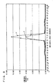
- Fig. 8 is a diagram illustrating the light distribution characteristic of light emission device 1 and bicycle taillight 2 utilizing light emission device 1 according to the present invention.
- the horizontal angle indicates the respective L and R angles shown in Fig 13A
- the vertical axis indicates the luminous intensity in the unit of cd.
- "a" indicated by a diamond-shaped mark represents the luminous intensity in LED body 10
- "b" indicated by a square-shaped mark represents the luminous intensity where light distribution member 20 is mounted on LED body 10
- "c” indicated by a triangular mark represents the luminous intensity where light emission device 1 is received in case 3 as bicycle taillight 2.
- a higher degree of brightness is obtained when LED body 10 is incorporated into light distribution member 20 as light emission device than when LED body 10 is by itself.
- the degree of brightness is seen to decrease significantly.
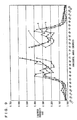
- Figs. 9 to 11 are diagrams illustrating the L and R angles indicating luminous intensity that is greater than a prescribed value, respectively.
- Fig. 9 represents the case in which each of the L and R angle is 15° or greater
- Fig. 10 represents the case in which each of the L and R angles is 30° or greater
- Fig. 11 represents the case in which each of the L and R angles is 70° or greater.
- LED body 10 has a value of approximately 0.030 cd around the LR angle of 110°, and as light emission device 1, has a brightness of approximately 0.050 cd, and as bicycle taillight 2, has a brightness of approximately 0.040 cd. From these diagrams, the light emission device and the bicycle taillight according to the present invention is seen to satisfy the regulation values for a bicycle taillight set forth in Germany shown in Fig. 12.
Landscapes
- Engineering & Computer Science (AREA)
- General Engineering & Computer Science (AREA)
- Mechanical Engineering (AREA)
- Non-Portable Lighting Devices Or Systems Thereof (AREA)
- Lighting Device Outwards From Vehicle And Optical Signal (AREA)
Claims (6)
- Dispositif émetteur de lumière (1), comprenant :un corps (10) de LED unique à forte luminance possédant une partie de sommet (12) et une partie cylindrique (13) reliée à la partie de sommet (12) ;un premier élément (21) de diffusion de lumière disposé au-dessus de ladite partie cylindrique (13) dudit corps (10) de LED dans le but de diffuser de la lumière vers le haut ; etun deuxième élément (22) de diffusion de lumière disposé de l'autre côté de la partie cylindrique (13) dudit corps (10) de LED pour diffuser de la lumière dans les directions latérales, dans lequel ledit premier élément (21) de diffusion de lumière a une forme de cône inversé en direction dudit corps (10) de LED.
- Dispositif émetteur de lumière (1) selon la revendication 1, dans lequel ledit premier élément (21) de diffusion de lumière est asymétrique par rapport audit deuxième élément (22) de diffusion de lumière.
- Dispositif émetteur de lumière (1) selon la revendication 1 ou 2, dans lequel ledit deuxième élément (22) de diffusion de lumière comporte une rainure en forme de V inversé sur ledit autre côté.
- Dispositif émetteur de lumière (1) selon l'une quelconque des revendications 1 à 3, dans lequel ledit deuxième élément (22) de diffusion de lumière comprend un troisième élément (24) de diffusion de lumière, et ledit troisième élément (24) de diffusion de lumière comporte une surface incurvée en forme d'auge en direction de ladite partie de sommet (12).
- Dispositif émetteur de lumière (1) selon l'une quelconque des revendications 1 à 4, dans lequel ledit premier élément (21) de diffusion de lumière et ledit deuxième élément (22) de diffusion de lumière sont intégrés.
- Feu arrière de bicyclette incorporant un dispositif émetteur de lumière selon l'une quelconque des revendications 1 à 5.
Priority Applications (1)
| Application Number | Priority Date | Filing Date | Title |
|---|---|---|---|
| DE29923416U DE29923416U1 (de) | 1998-12-24 | 1999-12-17 | Leuchtvorrichtung geeignet als Fahrradrücklicht |
Applications Claiming Priority (2)
| Application Number | Priority Date | Filing Date | Title |
|---|---|---|---|
| JP36770298A JP3411964B2 (ja) | 1998-12-24 | 1998-12-24 | 自転車用テールライト |
| JP36770298 | 1998-12-24 |
Publications (2)
| Publication Number | Publication Date |
|---|---|
| EP1013543A1 EP1013543A1 (fr) | 2000-06-28 |
| EP1013543B1 true EP1013543B1 (fr) | 2001-10-04 |
Family
ID=18489987
Family Applications (1)
| Application Number | Title | Priority Date | Filing Date |
|---|---|---|---|
| EP99125220A Expired - Lifetime EP1013543B1 (fr) | 1998-12-24 | 1999-12-17 | Dispositif émetteur de lumière pour feu arrière de bicyclette |
Country Status (6)
| Country | Link |
|---|---|
| EP (1) | EP1013543B1 (fr) |
| JP (1) | JP3411964B2 (fr) |
| CN (1) | CN1114785C (fr) |
| DE (1) | DE69900329T2 (fr) |
| DK (1) | DK1013543T3 (fr) |
| TW (1) | TW422792B (fr) |
Families Citing this family (1)
| Publication number | Priority date | Publication date | Assignee | Title |
|---|---|---|---|---|
| DE102006023873A1 (de) * | 2006-05-19 | 2007-11-22 | Busch & Müller KG | Rücklicht für ein Zweirad |
Citations (1)
| Publication number | Priority date | Publication date | Assignee | Title |
|---|---|---|---|---|
| EP0940331A1 (fr) * | 1998-03-06 | 1999-09-08 | Spanninga Metaal B.V. | Feu arrière |
Family Cites Families (4)
| Publication number | Priority date | Publication date | Assignee | Title |
|---|---|---|---|---|
| US5173810A (en) * | 1991-08-21 | 1992-12-22 | Aisens Co., Ltd. | Light transmitting lens for use with a photoelectric sensor |
| CH682142A5 (fr) * | 1992-04-14 | 1993-07-30 | Ver Drahtwerke Ag | |
| DE4224061C5 (de) * | 1992-07-21 | 2010-03-11 | Busch & Müller KG | Fahrzeugrückleuchte mit Leuchtdiode |
| DE4433882C2 (de) * | 1993-09-22 | 1998-04-16 | Busch & Mueller | Fahrradschlußleuchte |
-
1998
- 1998-12-24 JP JP36770298A patent/JP3411964B2/ja not_active Expired - Fee Related
-
1999
- 1999-12-13 TW TW088121741A patent/TW422792B/zh not_active IP Right Cessation
- 1999-12-17 DK DK99125220T patent/DK1013543T3/da active
- 1999-12-17 EP EP99125220A patent/EP1013543B1/fr not_active Expired - Lifetime
- 1999-12-17 DE DE69900329T patent/DE69900329T2/de not_active Expired - Lifetime
- 1999-12-24 CN CN99127062A patent/CN1114785C/zh not_active Expired - Fee Related
Patent Citations (1)
| Publication number | Priority date | Publication date | Assignee | Title |
|---|---|---|---|---|
| EP0940331A1 (fr) * | 1998-03-06 | 1999-09-08 | Spanninga Metaal B.V. | Feu arrière |
Also Published As
| Publication number | Publication date |
|---|---|
| JP3411964B2 (ja) | 2003-06-03 |
| JP2000185681A (ja) | 2000-07-04 |
| EP1013543A1 (fr) | 2000-06-28 |
| CN1114785C (zh) | 2003-07-16 |
| CN1257980A (zh) | 2000-06-28 |
| DE69900329D1 (de) | 2001-11-08 |
| DE69900329T2 (de) | 2002-07-04 |
| TW422792B (en) | 2001-02-21 |
| DK1013543T3 (da) | 2001-12-27 |
Similar Documents
| Publication | Publication Date | Title |
|---|---|---|
| JP3195294B2 (ja) | 車両用灯具 | |
| US6834986B2 (en) | Head lamp for bicycle | |
| US7339200B2 (en) | Light-emitting diode and vehicular lamp | |
| US7070311B2 (en) | Vehicle light for producing light whose form depends on orientations of plural refraction elements | |
| US8256943B2 (en) | Vehicle light | |
| US7290908B2 (en) | Vehicular lamp | |
| US11067254B1 (en) | Auxiliary light for mounting to a vehicle | |
| AU1505601A (en) | Light emitting diode reflector | |
| US11828428B1 (en) | Vehicle lamp structure | |
| CN113898921B (zh) | 矩阵式分布的汽车信号灯光学结构及车灯 | |
| KR20230171304A (ko) | 차량용 램프 모듈 및 그 램프 모듈을 포함하는 차량용 램프 | |
| JPH0238999B2 (fr) | ||
| EP1013543B1 (fr) | Dispositif émetteur de lumière pour feu arrière de bicyclette | |
| US10746918B2 (en) | Light assembly and light guide | |
| US20090086499A1 (en) | Car spoiler having light-emitting effect | |
| US20010053077A1 (en) | Electric torches | |
| JPH038204A (ja) | Ledランプ装置 | |
| JPH0145162B2 (fr) | ||
| JPH039107Y2 (fr) | ||
| JPS61171177A (ja) | Led光源体 | |
| JPH039108Y2 (fr) | ||
| JP2000149632A (ja) | 放光灯 | |
| JPH028404B2 (fr) | ||
| JPH036937Y2 (fr) | ||
| US20190145602A1 (en) | Light device for a vehicle |
Legal Events
| Date | Code | Title | Description |
|---|---|---|---|
| PUAI | Public reference made under article 153(3) epc to a published international application that has entered the european phase |
Free format text: ORIGINAL CODE: 0009012 |
|
| 17P | Request for examination filed |
Effective date: 20000427 |
|
| AK | Designated contracting states |
Kind code of ref document: A1 Designated state(s): DE DK FR GB |
|
| AX | Request for extension of the european patent |
Free format text: AL;LT;LV;MK;RO;SI |
|
| 17Q | First examination report despatched |
Effective date: 20000712 |
|
| GRAG | Despatch of communication of intention to grant |
Free format text: ORIGINAL CODE: EPIDOS AGRA |
|
| AKX | Designation fees paid |
Free format text: DE DK FR GB |
|
| GRAG | Despatch of communication of intention to grant |
Free format text: ORIGINAL CODE: EPIDOS AGRA |
|
| GRAH | Despatch of communication of intention to grant a patent |
Free format text: ORIGINAL CODE: EPIDOS IGRA |
|
| GRAH | Despatch of communication of intention to grant a patent |
Free format text: ORIGINAL CODE: EPIDOS IGRA |
|
| GRAA | (expected) grant |
Free format text: ORIGINAL CODE: 0009210 |
|
| AK | Designated contracting states |
Kind code of ref document: B1 Designated state(s): DE DK FR GB |
|
| REF | Corresponds to: |
Ref document number: 69900329 Country of ref document: DE Date of ref document: 20011108 |
|
| ET | Fr: translation filed | ||
| REG | Reference to a national code |
Ref country code: GB Ref legal event code: IF02 |
|
| PLBE | No opposition filed within time limit |
Free format text: ORIGINAL CODE: 0009261 |
|
| STAA | Information on the status of an ep patent application or granted ep patent |
Free format text: STATUS: NO OPPOSITION FILED WITHIN TIME LIMIT |
|
| 26N | No opposition filed | ||
| PGFP | Annual fee paid to national office [announced via postgrant information from national office to epo] |
Ref country code: DK Payment date: 20081212 Year of fee payment: 10 |
|
| PGFP | Annual fee paid to national office [announced via postgrant information from national office to epo] |
Ref country code: FR Payment date: 20081212 Year of fee payment: 10 |
|
| PGFP | Annual fee paid to national office [announced via postgrant information from national office to epo] |
Ref country code: GB Payment date: 20081217 Year of fee payment: 10 |
|
| REG | Reference to a national code |
Ref country code: DK Ref legal event code: EBP |
|
| GBPC | Gb: european patent ceased through non-payment of renewal fee |
Effective date: 20091217 |
|
| REG | Reference to a national code |
Ref country code: FR Ref legal event code: ST Effective date: 20100831 |
|
| PG25 | Lapsed in a contracting state [announced via postgrant information from national office to epo] |
Ref country code: FR Free format text: LAPSE BECAUSE OF NON-PAYMENT OF DUE FEES Effective date: 20091231 |
|
| PG25 | Lapsed in a contracting state [announced via postgrant information from national office to epo] |
Ref country code: GB Free format text: LAPSE BECAUSE OF NON-PAYMENT OF DUE FEES Effective date: 20091217 |
|
| PG25 | Lapsed in a contracting state [announced via postgrant information from national office to epo] |
Ref country code: DK Free format text: LAPSE BECAUSE OF NON-PAYMENT OF DUE FEES Effective date: 20100104 |
|
| PGFP | Annual fee paid to national office [announced via postgrant information from national office to epo] |
Ref country code: DE Payment date: 20101215 Year of fee payment: 12 |
|
| REG | Reference to a national code |
Ref country code: DE Ref legal event code: R119 Ref document number: 69900329 Country of ref document: DE Effective date: 20130702 |
|
| PG25 | Lapsed in a contracting state [announced via postgrant information from national office to epo] |
Ref country code: DE Free format text: LAPSE BECAUSE OF NON-PAYMENT OF DUE FEES Effective date: 20130702 |