EP1013590A2 - Dispositif pour plier et transporter des produits plats imprimés dans une machine rotative imprimante - Google Patents
Dispositif pour plier et transporter des produits plats imprimés dans une machine rotative imprimante Download PDFInfo
- Publication number
- EP1013590A2 EP1013590A2 EP99124294A EP99124294A EP1013590A2 EP 1013590 A2 EP1013590 A2 EP 1013590A2 EP 99124294 A EP99124294 A EP 99124294A EP 99124294 A EP99124294 A EP 99124294A EP 1013590 A2 EP1013590 A2 EP 1013590A2
- Authority
- EP
- European Patent Office
- Prior art keywords
- gripper
- folding
- arm
- folding cylinder
- printed products
- Prior art date
- Legal status (The legal status is an assumption and is not a legal conclusion. Google has not performed a legal analysis and makes no representation as to the accuracy of the status listed.)
- Granted
Links
Images


Classifications
-
- B—PERFORMING OPERATIONS; TRANSPORTING
- B65—CONVEYING; PACKING; STORING; HANDLING THIN OR FILAMENTARY MATERIAL
- B65H—HANDLING THIN OR FILAMENTARY MATERIAL, e.g. SHEETS, WEBS, CABLES
- B65H45/00—Folding thin material
- B65H45/12—Folding articles or webs with application of pressure to define or form crease lines
- B65H45/16—Rotary folders
- B65H45/162—Rotary folders with folding jaw cylinders
- B65H45/163—Details of folding jaws therefor
-
- B—PERFORMING OPERATIONS; TRANSPORTING
- B65—CONVEYING; PACKING; STORING; HANDLING THIN OR FILAMENTARY MATERIAL
- B65H—HANDLING THIN OR FILAMENTARY MATERIAL, e.g. SHEETS, WEBS, CABLES
- B65H29/00—Delivering or advancing articles from machines; Advancing articles to or into piles
- B65H29/02—Delivering or advancing articles from machines; Advancing articles to or into piles by mechanical grippers engaging the leading edge only of the articles
- B65H29/06—Delivering or advancing articles from machines; Advancing articles to or into piles by mechanical grippers engaging the leading edge only of the articles the grippers being carried by rotating members
-
- B—PERFORMING OPERATIONS; TRANSPORTING
- B65—CONVEYING; PACKING; STORING; HANDLING THIN OR FILAMENTARY MATERIAL
- B65H—HANDLING THIN OR FILAMENTARY MATERIAL, e.g. SHEETS, WEBS, CABLES
- B65H29/00—Delivering or advancing articles from machines; Advancing articles to or into piles
- B65H29/68—Reducing the speed of articles as they advance
-
- B—PERFORMING OPERATIONS; TRANSPORTING
- B65—CONVEYING; PACKING; STORING; HANDLING THIN OR FILAMENTARY MATERIAL
- B65H—HANDLING THIN OR FILAMENTARY MATERIAL, e.g. SHEETS, WEBS, CABLES
- B65H45/00—Folding thin material
- B65H45/12—Folding articles or webs with application of pressure to define or form crease lines
- B65H45/16—Rotary folders
- B65H45/162—Rotary folders with folding jaw cylinders
- B65H45/164—Details of folding blades therefor
Definitions
- the present invention relates to a device for folding and for transporting flat Print products in a rotary printing press according to the preamble of Claim 1.
- the flap folder known from the prior art in which one with a fixed folding knife cooperating jaw is used, have the Advantage that they produce a relatively precise cross fold, or generally flap fold, without smearing the printed products.
- the state of the art Flap folder apparatus known in the art are, however, maximum with regard to the number limited to fold pages at the same time, which is due to the limited engagement of the Folding knife and the jaws, as well as the distance between the folding knife and the Folding jaw cylinder is due to the generation of the fold. So you can for example, with typical flap folders only 64 or fewer pages fold precisely at the same time.
- drum or wheel folding units In the so-called drum or wheel folding units, the folding or Signatures held by a cylinder from the peripheral surface ejecting folding knife between two spring-mounted rotating folding rollers encountered, which fold the superimposed signatures in the transverse direction.
- drum or wheel folding units with up to 160 foldable at the same time Newspaper pages can achieve high production performance, they have Devices have the disadvantage that the cross fold has very little precision and this is not suitable, for example, for inserting supplements.
- a Device according to the invention a folding cylinder on which the to be folded, in essential flat printed product, or the superimposed to be folded, in essential flat printed products are carried, as well as at least one arm attached to its first end is arranged rotatable about an axis, and that at its second End is provided with a gripper device, which is guided on the folding cylinder Grabs the printed product in the area of the fold to be made, lifts it off the folding cylinder, transported further and provided with a fold during further transport.
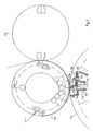
- Fig. 1 shows a folding section 100 of a rotary printing press, which one in web 106 printed on the upstream printing units of the rotary printing press between a cutting cylinder 102 and one arranged close to it Folding cylinder 104 for separating signatures, i. H. generally speaking, for Production of flat or flat products or printed products.
- the cutting cylinder 102 can comprise two knives 108 which rotate counterclockwise with the cutting cylinder 102.
- the folding cylinder 104 can be formed in any known manner.
- the folding cylinder contains two cutting strips or slot strips 110, which are with the folding cylinder 104 turn clockwise.
- the movement of the cutting cylinder and the folding cylinder is synchronized in a known manner so that part of the web 106 enters a gap between the cutting cylinder and the folding cylinder in which it is separated by one of the knives 108, which counter through the web 106 presses an associated slot bar 110 on the folding cylinder 104.
- the leading edge the web 106 is produced, it is z. B. of pin needles impaled, one of two cam-controlled puncture needle assemblies 112 is used, the leading edge on the surface of the in a known manner Secure folding cylinder 104.
- the folding cylinder 104 serves as a transport device for transporting a flat one Product, such as web 106 or any part thereof, from which gap formed between the cutting cylinder 102 and the folding cylinder 104 into a Delay drum 114.
- the folding cylinder 104 can be used according to a preferred embodiment of the invention any known folding knife arrangement for producing a cross fold be formed.
- the folding cylinder 104 can be at least one fixed (e.g. extended, non-retractable) or preferably include a retractable folding knife 120. 1 in the embodiment two folding knives 120 in connection with an optional, fixed cam 116 shown for retracting and extending the folding knife 120 during operation.
- Control rollers 118 which rotate with the folding cylinder 104, move along the Outer circumference of the cam 116.
- the control rollers 118 are with the folding blades 120 coupled, which depending on the position of a control roller 118 from the peripheral surface of the Folding cylinder 104 out or moved back into this.
- the folding cylinder 104 contains according to the preferred embodiment of the invention preferably two Puncture needle arrangements with which the trailing edge of the signature is impaled and can be held on the peripheral surface of the folding cylinder 104 while one immediately preceding signature by the delay drum from the Folding cylinder 104 is removed.
- the Folding cylinder 104 contain two opposing control rollers 118.
- the signature 122 of the Folding cylinder 104 is pressed radially outwards so that it is removed from a gripper device Delay drum 114 can be gripped safely.
- the signature 122 becomes separated by the knife 108 from the folding cylinder over an angular range around z. B. transported 180 °.
- the cam-controlled folding knife 120 pushes a part of this position (usually the Middle) of the signature from the folding cylinder surface radially outwards, so that this of a gripper element of the delay drum 114 can be gripped.
- the deceleration drum 114 includes at least one arm 124 that is about an axis 126 is rotatably connected to the delay drum 114, and which with the Deceleration drum 114 also rotates when the drum rotates about an axis 134.
- the arm 124 has a gripper device 128, which at a second end of the Arms 124 is arranged.
- the Gripper device 128 a gripper with a movably attached gripper finger 130 and a fixed gripper bar 132 that extends radially outward extending folding knife 120 of the folding cylinder 104 cooperate to the signature 122 to be recorded at the point at which the signature is to be folded.
- the arm 124 and the associated ones Gripper device 128 of the embodiment according to the invention shown in FIG. 1 so configures the gripper device 128 in the first position toward the Surface normal of the folding cylinder 104 is aligned.
- This first position will preferably over a predetermined angle of rotation range of the arm Maintain axis of rotation 134 of the deceleration drum.
- the gripper device is aligned so that the gripper bar 132 along a radial axis of the folding cylinder 104, i.e. H. one perpendicular to the surface of the Folding cylinder 104 and axis extending to the surface of the signature 122 (Surface normal).
- This radial alignment is over a Angular rotation range of the delay drum 114 z. B. by swiveling the Retain gripper device 128 or the gripper bar 132, which is sufficient for that appropriately aligns the gripper device 128 with respect to the signature 122 then take the signature 122 at the point where it is to be folded, and the Subsequently remove the signature radially from the folding cylinder 104.
- this angular range is approximately 45 °; however he can also have any value that is used to align the gripper device and to carry out the gripping process at a predetermined rotational speed of the Deceleration drum 114 and the folding cylinder 104 is sufficient.
- the delay drum 114 shown in Fig. 1 includes four arms 124, one on each a gripper device 128 is attached. Each of the arms 124 is on its axis of rotation 126 attached by a bolt or pin 136 to an eccentric disk 140 which is about the Axis 134 of the deceleration drum moves.
- the eccentric disc attachment changes the speed of the Arms 124 as it rotates about axis 134 of deceleration drum 114.
- the arms 124 preferably reach their maximum rotational speed when they are aligned in the position in which a signature 122 is captured. In connection this slows the movement of the arms when they move counterclockwise from the takeover position above the Deceleration drum 114 moved counterclockwise to a lower position, as shown in Fig. 1.
- Each of the arms 124 includes a connector 139 which has a roller that moves along the circumference of a fixed cam 138. Furthermore, a connector 142 is used to allow interaction between the To reach connecting element 139 and the eccentric disc 140.
- the fixed one Curve 138 is used in conjunction with connector 139 to the movably attached gripper fingers 130 to either gripper device 128 close or open. For this reason, the shape of the control curve 138 changes the location where the gripper device 128 accepts a signature and changes then again at the point at which the gripper device transfers the signature to the subordinate conveyor passes. As shown in Fig. 1, the resulting recess in the control curve 138 over a range of approximately 120 °, can however also extend over a larger or smaller area.
- any Gripper device articulated about an axis independently of the arm 124 preferably be pivotally attached.
- the articulation of each gripper device is the further in response to the combined lateral and radial movement of the Connector 139 controlled by its rotation with the delay drum.
- Around to illustrate this are three positions of an inventive one Gripper device 128 shown in and around arm 124 position in FIG the signature 122 is seized. These three positions are shown in FIG. 2 shown in more detail.
- Gripper device 128 articulated by means of an axis 202 in the manner with an arm 124 the delay drum 114 connected that the preferably fixed Gripper bar 132 a radially aligned position with respect to a vertical or Surface normals of the surface of the folding cylinder 104 and the surface of the folding signature 122 retained.
- maintaining this alignment of signature 122 is preferably performed by the insert of the connecting element 139 for controlling the rotational movement of the Gripper device 128 reached around axis 202.
- Connecting element preferably also together with the control cam 138 in order an opening and closing of the movably attached gripper finger to control what z. B. via additional connecting elements and levers 204, 206 and 208 in the in FIG. 2 shown way can be done.
- a stop position of the is movable attached gripper finger 130 preferably via a spring-loaded stop 210 controlled.
- the spring-loaded stop 210 can be a compression spring 212, for example contain, which a spring plunger 214 against one on a hinge connection 208th attached movable roller 216 urges.
- This allows the gripper device 128 in advantageously without setting a large number of signatures different thickness or to a different number of signatures that to be folded by the device according to the invention, in addition the maximum page size is significantly higher than the maximum page size using conventional flap folding devices can be processed simultaneously.
- the movably attached gripper finger 130 itself can also be spring-loaded, which increases the area of the pages that can be folded at the same time or signatures, and thus results in greater flexibility of the device.
- arm 124 rotates counterclockwise about the axis 134 about which Slow down signature.
- arm 124 and the associated gripper device slow down to one Speed that is approximately 20% of the top speed at the time of acquisition corresponds to a signature.
- An increasing slowdown of the arm 124 is shown in the figures by increasing the angle between the Arm 124 and the connecting element 142 indicated. So is the angle between them Elements z. B. relatively large (z. B.
- movably attached gripper finger 130 is opened.
- Fig. 1 and Fig. 3 shows how an inventive Gripper device 128 is moved to a position near a conveyor gripper 144.
- the movably attached gripper finger 130 is pushed through Interaction of the connecting element 139 and the control curve 138 opened.
- a control cam device not shown in the figures, can be provided over which one coincides with the opening of the movable gripper finger 130 Closing the conveyor gripper 144 is controlled so that the Passing the signature 122 takes place in the so-called gripper closure, the z. B. from Sheet-fed rotary printing presses are known. This gives the advantage of one always controlled transport of the folded signature 122.
- folding cylinder with a retractable one Folding knife, for example, a folding cylinder with a fixed folding knife use that with the gripper devices 128 on the arms 124 of the Delay drum 114 cooperates.
- any type of fold including a double one Parallel fold are generated.
- any type of fold including a double one Parallel fold.
- arms 124 of the deceleration drum 114 which are in the Figures are shown only in cross section, not as a one-piece arm, but in shape of multiple juxtaposed arms that span across the width the delay drum 114, with each arm 124 one can carry corresponding gripper device 128 according to the invention.
- arms 124 and / or gripper devices 128 as a single arm and / or as single gripper device with a width equal to the width of a given signature corresponds, or be configured to any desired width.
- the device according to the invention thus offers the advantage that with a single Device for folding signatures or generally flat products, as well also a controlled handover of the products to a subordinate Gripper conveyor is made possible, while still slowing the on the folding cylinder with a high speed corresponding to the printing press speed Speed generated signatures on one for further processing in one Postprocessing device suitable low speed takes place.
- This can another slowdown device for the signatures, as in conventional Folders are used, which results in a significantly lower space requirement of the entire folding arrangement.
Landscapes
- Engineering & Computer Science (AREA)
- Mechanical Engineering (AREA)
- Folding Of Thin Sheet-Like Materials, Special Discharging Devices, And Others (AREA)
Applications Claiming Priority (2)
| Application Number | Priority Date | Filing Date | Title |
|---|---|---|---|
| US09/208,250 US6322487B1 (en) | 1998-12-09 | 1998-12-09 | Method and apparatus for delivery of flat printed products |
| US208250 | 1998-12-09 |
Publications (3)
| Publication Number | Publication Date |
|---|---|
| EP1013590A2 true EP1013590A2 (fr) | 2000-06-28 |
| EP1013590A3 EP1013590A3 (fr) | 2002-05-02 |
| EP1013590B1 EP1013590B1 (fr) | 2004-03-03 |
Family
ID=22773881
Family Applications (1)
| Application Number | Title | Priority Date | Filing Date |
|---|---|---|---|
| EP99124294A Expired - Lifetime EP1013590B1 (fr) | 1998-12-09 | 1999-12-06 | Dispositif pour plier et transporter des produits plats imprimés dans une machine rotative imprimante |
Country Status (5)
| Country | Link |
|---|---|
| US (1) | US6322487B1 (fr) |
| EP (1) | EP1013590B1 (fr) |
| JP (1) | JP2000177926A (fr) |
| AT (1) | ATE260860T1 (fr) |
| DE (2) | DE59908728D1 (fr) |
Families Citing this family (4)
| Publication number | Priority date | Publication date | Assignee | Title |
|---|---|---|---|---|
| JP3738418B2 (ja) * | 2001-07-18 | 2006-01-25 | 株式会社東京機械製作所 | 折畳部の咥え装置 |
| JP3697694B2 (ja) * | 2002-05-09 | 2005-09-21 | 株式会社東京機械製作所 | 輪転機の折部の咥え装置 |
| US20050272586A1 (en) * | 2004-06-04 | 2005-12-08 | Germain Patrick C S | Gripper for a web folding cylinder |
| US8425392B2 (en) * | 2005-12-27 | 2013-04-23 | Goss International Americas, Inc. | Broadsheet newspaper printing press and folder |
Family Cites Families (27)
| Publication number | Priority date | Publication date | Assignee | Title |
|---|---|---|---|---|
| DE1051110B (de) | 1952-03-27 | 1959-02-19 | Josef Burgmer | Greifereinrichtung fuer Papierquerschneidemaschinen |
| US3224306A (en) | 1962-10-09 | 1965-12-21 | Ael Dev And Res Division Inc | Automatic cutting and collating machine and method |
| US3675522A (en) | 1970-05-13 | 1972-07-11 | Hexcel Corp | Method and apparatus for stacking sheets |
| US3999454A (en) | 1975-10-20 | 1976-12-28 | George Hantscho Company, Inc. | Pinless feeder |
| DE2557866B2 (de) | 1975-12-22 | 1977-11-03 | Heidelberger Druckmaschinen Ag, 6900 Heidelberg | Rotierende vorgreifertrommel |
| NL7701897A (nl) | 1977-02-22 | 1978-08-24 | Meulen Leonard V D | Inrichting voor het afleggen van stukken folie- materiaal. |
| US4132403A (en) | 1977-07-07 | 1979-01-02 | Veb Polygraph Leipzig Kombinat Fuer Polygraphische Maschinen Und Ausruestungen | Sheet transfer apparatus for printing machine |
| US4283973A (en) | 1979-11-15 | 1981-08-18 | Paper Converting Machine Company | Method and apparatus for handling articles |
| US4385537A (en) | 1980-05-24 | 1983-05-31 | E.C.H. Will (Gmbh & Co.) | Apparatus for engaging and transporting discrete sheets of paper or the like |
| DE3404459A1 (de) | 1984-02-08 | 1985-08-14 | Frankenthal Ag Albert | Verfahren und vorrichtung zur auslage bogenfoermiger produkte in form eines schuppenstromes |
| US4781091A (en) | 1984-02-22 | 1988-11-01 | Meinan Machinery Works, Inc. | Conveyor system for conveying veneer sheets with spacings therebetween |
| DE3603781A1 (de) | 1986-02-06 | 1987-08-13 | Roland Man Druckmasch | Vorrichtung zur uebernahme und zum weitertransport von falzprodukten |
| US4919027A (en) | 1986-04-04 | 1990-04-24 | Littleton Industrial Consultants, Inc. | Sheet diverting and delivery system |
| US4765214A (en) | 1987-05-14 | 1988-08-23 | Meinan Machinery Works, Inc. | Apparatus for handling veneer sheets |
| US5293797A (en) | 1989-12-22 | 1994-03-15 | John Brown, Inc. | Multiple point delivery apparatus for separating of sheet-like elements |
| NO901737L (no) | 1990-04-19 | 1991-10-21 | Norlito Maskin As | Pakkemaskin for blader (stakker). |
| US5249493A (en) | 1992-01-21 | 1993-10-05 | Heidelberg-Harris Gmbh | Device for extracting samples from a folder |
| DE4215911C2 (de) * | 1992-05-14 | 1996-01-04 | Wifag Maschf | Falzklappen-Zylinder |
| DE4316134C2 (de) * | 1993-05-13 | 1997-03-13 | Heidelberger Druckmasch Ag | Verfahren zur Querfalzung von Bahnen sowie Falzapparat zur Durchführung des Verfahrens |
| US5452886A (en) | 1993-08-09 | 1995-09-26 | Heidelberger Druckmaschinen Ag | Device for slowing down signatures in a folding machine |
| FR2711576B1 (fr) * | 1993-10-26 | 1996-01-19 | Heidelberg Harris Sa | Dispositif de commande de l'accumulation ou non accumulation d'un cylindre coupeur-accumulateur d'une plieuse. |
| DE29502957U1 (de) * | 1995-02-22 | 1995-04-06 | MAN Roland Druckmaschinen AG, 63075 Offenbach | Zylinder in einem Falzwerk mit vertellbarem Durchmesser |
| EP0734988B1 (fr) * | 1995-03-25 | 2001-09-26 | Koenig & Bauer Aktiengesellschaft | Méthode et appareil pour mettre en mouvement des aiguilles de perforation |
| US5855153A (en) * | 1996-09-04 | 1999-01-05 | Heidelberg Harris Inc. | Method and apparatus for conveying flat printed products |
| JPH1076630A (ja) * | 1996-09-06 | 1998-03-24 | Toshiba Mach Co Ltd | 輪転印刷機の折装置 |
| ES2149549T3 (es) * | 1996-10-15 | 2000-11-01 | Komori Printing Mach | Plegadora sin agujas. |
| US5927712A (en) * | 1996-11-12 | 1999-07-27 | Heidelberg Harris | Sample signature delivery having alternate transport path away from deceleration device |
-
1998
- 1998-12-09 US US09/208,250 patent/US6322487B1/en not_active Expired - Lifetime
-
1999
- 1999-12-06 DE DE59908728T patent/DE59908728D1/de not_active Expired - Lifetime
- 1999-12-06 EP EP99124294A patent/EP1013590B1/fr not_active Expired - Lifetime
- 1999-12-06 JP JP11346573A patent/JP2000177926A/ja active Pending
- 1999-12-06 DE DE19958739A patent/DE19958739A1/de not_active Withdrawn
- 1999-12-06 AT AT99124294T patent/ATE260860T1/de not_active IP Right Cessation
Also Published As
| Publication number | Publication date |
|---|---|
| DE19958739A1 (de) | 2000-06-15 |
| ATE260860T1 (de) | 2004-03-15 |
| US6322487B1 (en) | 2001-11-27 |
| EP1013590B1 (fr) | 2004-03-03 |
| DE59908728D1 (de) | 2004-04-08 |
| EP1013590A3 (fr) | 2002-05-02 |
| JP2000177926A (ja) | 2000-06-27 |
Similar Documents
| Publication | Publication Date | Title |
|---|---|---|
| DE2921383C2 (de) | Papierfalzmaschine zur Verwendung an einer Rotationsdruckmaschine | |
| EP0883566B1 (fr) | Plieuse a lames | |
| CH642030A5 (de) | Vorrichtung zur herstellung von falzprodukten, insbesondere fuer rollenrotationsdruckmaschinen. | |
| EP0911291A2 (fr) | Dispositif de pliage dans une machine plieuse à grande vitesse | |
| EP0977668B1 (fr) | Dispositif pour regler des machoires de pliage | |
| EP0656307B1 (fr) | Cylindre de transport de cahiers | |
| EP0931747B1 (fr) | Plieuse pour machine rotative à imprimer | |
| EP1362819B1 (fr) | Plieuse dans une machine rotative d'impression | |
| DE2517000A1 (de) | Falzapparat fuer quergefalzte und/ oder laengsgefalzte produkte fuer buecher und umschlaege | |
| DE19716628C2 (de) | Verfahren und Vorrichtung zum Querfalzen von Signaturen | |
| EP0931748B1 (fr) | Plieuse sans pointure pour machines rotatives à imprimer | |
| EP1074500A1 (fr) | Cylindre de transport de produits d'imprimerie d'un appareil de pliage | |
| DE2533432A1 (de) | Falzapparat | |
| DE3621820A1 (de) | Falz- und transportvorrichtung | |
| WO2014131474A1 (fr) | Appareil de pliage pourvu d'un premier cylindre collecteur et d'un deuxième cylindre collecteur | |
| EP0827930B1 (fr) | Dispositif pour transporter des produits plats imprimés | |
| EP1013590B1 (fr) | Dispositif pour plier et transporter des produits plats imprimés dans une machine rotative imprimante | |
| DE10102220A1 (de) | Vorrichtung zum Halten von Produkten auf einer Transportoberfläche in einem Falzapparat | |
| EP1207128B1 (fr) | Appareil de pliage muni d'un dispositif de guidage | |
| EP1712499A1 (fr) | Cylindre plieur avec un corps cylindrique et au moins un dispositif de préhension | |
| EP2061714A1 (fr) | Plieuses avec un cylindre à lames de pliage et un cylindre à volets plieurs | |
| DE19949938A1 (de) | Verfahren zum Falzen von Signaturen und Falzapparat mit Bremsgreifern | |
| DE3143011A1 (de) | Steuerkurvenbetaetigte greifvorrichtung fuer bedruckte papierbahnen | |
| DE19716625A1 (de) | Einrichtung zum Vorfalzen von Signaturen | |
| DE102004016109A1 (de) | Schaufelradauslage für einen Falzapparat |
Legal Events
| Date | Code | Title | Description |
|---|---|---|---|
| PUAI | Public reference made under article 153(3) epc to a published international application that has entered the european phase |
Free format text: ORIGINAL CODE: 0009012 |
|
| AK | Designated contracting states |
Kind code of ref document: A2 Designated state(s): AT BE CH CY DE DK ES FI FR GB GR IE IT LI LU MC NL PT SE |
|
| AX | Request for extension of the european patent |
Free format text: AL;LT;LV;MK;RO;SI |
|
| PUAL | Search report despatched |
Free format text: ORIGINAL CODE: 0009013 |
|
| AK | Designated contracting states |
Kind code of ref document: A3 Designated state(s): AT BE CH CY DE DK ES FI FR GB GR IE IT LI LU MC NL PT SE |
|
| AX | Request for extension of the european patent |
Free format text: AL;LT;LV;MK;RO;SI |
|
| 17P | Request for examination filed |
Effective date: 20020319 |
|
| AKX | Designation fees paid |
Free format text: AT BE CH CY DE DK ES FI FR GB GR IE IT LI LU MC NL PT SE |
|
| GRAP | Despatch of communication of intention to grant a patent |
Free format text: ORIGINAL CODE: EPIDOSNIGR1 |
|
| GRAS | Grant fee paid |
Free format text: ORIGINAL CODE: EPIDOSNIGR3 |
|
| GRAA | (expected) grant |
Free format text: ORIGINAL CODE: 0009210 |
|
| AK | Designated contracting states |
Kind code of ref document: B1 Designated state(s): AT BE CH CY DE DK ES FI FR GB GR IE IT LI LU MC NL PT SE |
|
| PG25 | Lapsed in a contracting state [announced via postgrant information from national office to epo] |
Ref country code: NL Free format text: LAPSE BECAUSE OF FAILURE TO SUBMIT A TRANSLATION OF THE DESCRIPTION OR TO PAY THE FEE WITHIN THE PRESCRIBED TIME-LIMIT Effective date: 20040303 Ref country code: IT Free format text: LAPSE BECAUSE OF FAILURE TO SUBMIT A TRANSLATION OF THE DESCRIPTION OR TO PAY THE FEE WITHIN THE PRESCRIBED TIME-LIMIT;WARNING: LAPSES OF ITALIAN PATENTS WITH EFFECTIVE DATE BEFORE 2007 MAY HAVE OCCURRED AT ANY TIME BEFORE 2007. THE CORRECT EFFECTIVE DATE MAY BE DIFFERENT FROM THE ONE RECORDED. Effective date: 20040303 Ref country code: IE Free format text: LAPSE BECAUSE OF FAILURE TO SUBMIT A TRANSLATION OF THE DESCRIPTION OR TO PAY THE FEE WITHIN THE PRESCRIBED TIME-LIMIT Effective date: 20040303 Ref country code: GB Free format text: LAPSE BECAUSE OF FAILURE TO SUBMIT A TRANSLATION OF THE DESCRIPTION OR TO PAY THE FEE WITHIN THE PRESCRIBED TIME-LIMIT Effective date: 20040303 Ref country code: FR Free format text: LAPSE BECAUSE OF FAILURE TO SUBMIT A TRANSLATION OF THE DESCRIPTION OR TO PAY THE FEE WITHIN THE PRESCRIBED TIME-LIMIT Effective date: 20040303 Ref country code: FI Free format text: LAPSE BECAUSE OF FAILURE TO SUBMIT A TRANSLATION OF THE DESCRIPTION OR TO PAY THE FEE WITHIN THE PRESCRIBED TIME-LIMIT Effective date: 20040303 Ref country code: CY Free format text: LAPSE BECAUSE OF FAILURE TO SUBMIT A TRANSLATION OF THE DESCRIPTION OR TO PAY THE FEE WITHIN THE PRESCRIBED TIME-LIMIT Effective date: 20040303 |
|
| REG | Reference to a national code |
Ref country code: GB Ref legal event code: FG4D Free format text: NOT ENGLISH |
|
| REG | Reference to a national code |
Ref country code: CH Ref legal event code: EP |
|
| REG | Reference to a national code |
Ref country code: IE Ref legal event code: FG4D Free format text: GERMAN |
|
| REF | Corresponds to: |
Ref document number: 59908728 Country of ref document: DE Date of ref document: 20040408 Kind code of ref document: P |
|
| PG25 | Lapsed in a contracting state [announced via postgrant information from national office to epo] |
Ref country code: SE Free format text: LAPSE BECAUSE OF FAILURE TO SUBMIT A TRANSLATION OF THE DESCRIPTION OR TO PAY THE FEE WITHIN THE PRESCRIBED TIME-LIMIT Effective date: 20040603 Ref country code: GR Free format text: LAPSE BECAUSE OF FAILURE TO SUBMIT A TRANSLATION OF THE DESCRIPTION OR TO PAY THE FEE WITHIN THE PRESCRIBED TIME-LIMIT Effective date: 20040603 Ref country code: DK Free format text: LAPSE BECAUSE OF FAILURE TO SUBMIT A TRANSLATION OF THE DESCRIPTION OR TO PAY THE FEE WITHIN THE PRESCRIBED TIME-LIMIT Effective date: 20040603 |
|
| PG25 | Lapsed in a contracting state [announced via postgrant information from national office to epo] |
Ref country code: ES Free format text: LAPSE BECAUSE OF FAILURE TO SUBMIT A TRANSLATION OF THE DESCRIPTION OR TO PAY THE FEE WITHIN THE PRESCRIBED TIME-LIMIT Effective date: 20040614 |
|
| NLV1 | Nl: lapsed or annulled due to failure to fulfill the requirements of art. 29p and 29m of the patents act | ||
| GBV | Gb: ep patent (uk) treated as always having been void in accordance with gb section 77(7)/1977 [no translation filed] |
Effective date: 20040303 |
|
| REG | Reference to a national code |
Ref country code: IE Ref legal event code: FD4D |
|
| RAP2 | Party data changed (patent owner data changed or rights of a patent transferred) |
Owner name: GOSS INTERNATIONAL AMERICAS, INC. |
|
| PG25 | Lapsed in a contracting state [announced via postgrant information from national office to epo] |
Ref country code: LU Free format text: LAPSE BECAUSE OF NON-PAYMENT OF DUE FEES Effective date: 20041206 Ref country code: AT Free format text: LAPSE BECAUSE OF NON-PAYMENT OF DUE FEES Effective date: 20041206 |
|
| PG25 | Lapsed in a contracting state [announced via postgrant information from national office to epo] |
Ref country code: MC Free format text: LAPSE BECAUSE OF NON-PAYMENT OF DUE FEES Effective date: 20041231 Ref country code: BE Free format text: LAPSE BECAUSE OF NON-PAYMENT OF DUE FEES Effective date: 20041231 |
|
| PLBE | No opposition filed within time limit |
Free format text: ORIGINAL CODE: 0009261 |
|
| STAA | Information on the status of an ep patent application or granted ep patent |
Free format text: STATUS: NO OPPOSITION FILED WITHIN TIME LIMIT |
|
| EN | Fr: translation not filed | ||
| 26N | No opposition filed |
Effective date: 20041206 |
|
| REG | Reference to a national code |
Ref country code: CH Ref legal event code: NV Representative=s name: KIRKER & CIE SA |
|
| BERE | Be: lapsed |
Owner name: *HEIDELBERGER DRUCKMASCHINEN A.G. Effective date: 20041231 |
|
| BERE | Be: lapsed |
Owner name: *HEIDELBERGER DRUCKMASCHINEN A.G. Effective date: 20041231 |
|
| PG25 | Lapsed in a contracting state [announced via postgrant information from national office to epo] |
Ref country code: PT Free format text: LAPSE BECAUSE OF NON-PAYMENT OF DUE FEES Effective date: 20040803 |
|
| PGFP | Annual fee paid to national office [announced via postgrant information from national office to epo] |
Ref country code: CH Payment date: 20101227 Year of fee payment: 12 |
|
| PGFP | Annual fee paid to national office [announced via postgrant information from national office to epo] |
Ref country code: DE Payment date: 20101229 Year of fee payment: 12 |
|
| REG | Reference to a national code |
Ref country code: CH Ref legal event code: PL |
|
| REG | Reference to a national code |
Ref country code: DE Ref legal event code: R119 Ref document number: 59908728 Country of ref document: DE Effective date: 20120703 |
|
| PG25 | Lapsed in a contracting state [announced via postgrant information from national office to epo] |
Ref country code: DE Free format text: LAPSE BECAUSE OF NON-PAYMENT OF DUE FEES Effective date: 20120703 Ref country code: CH Free format text: LAPSE BECAUSE OF NON-PAYMENT OF DUE FEES Effective date: 20111231 Ref country code: LI Free format text: LAPSE BECAUSE OF NON-PAYMENT OF DUE FEES Effective date: 20111231 |