EP1013594A2 - Zugelement-Wegesensor - Google Patents
Zugelement-Wegesensor Download PDFInfo
- Publication number
- EP1013594A2 EP1013594A2 EP99125624A EP99125624A EP1013594A2 EP 1013594 A2 EP1013594 A2 EP 1013594A2 EP 99125624 A EP99125624 A EP 99125624A EP 99125624 A EP99125624 A EP 99125624A EP 1013594 A2 EP1013594 A2 EP 1013594A2
- Authority
- EP
- European Patent Office
- Prior art keywords
- winding drum
- winding
- tension element
- magnets
- displacement sensor
- Prior art date
- Legal status (The legal status is an assumption and is not a legal conclusion. Google has not performed a legal analysis and makes no representation as to the accuracy of the status listed.)
- Withdrawn
Links
Images







Classifications
-
- G—PHYSICS
- G01—MEASURING; TESTING
- G01B—MEASURING LENGTH, THICKNESS OR SIMILAR LINEAR DIMENSIONS; MEASURING ANGLES; MEASURING AREAS; MEASURING IRREGULARITIES OF SURFACES OR CONTOURS
- G01B3/00—Measuring instruments characterised by the use of mechanical techniques
- G01B3/11—Chains for measuring length
-
- G—PHYSICS
- G01—MEASURING; TESTING
- G01B—MEASURING LENGTH, THICKNESS OR SIMILAR LINEAR DIMENSIONS; MEASURING ANGLES; MEASURING AREAS; MEASURING IRREGULARITIES OF SURFACES OR CONTOURS
- G01B7/00—Measuring arrangements characterised by the use of electric or magnetic techniques
- G01B7/02—Measuring arrangements characterised by the use of electric or magnetic techniques for measuring length, width or thickness
- G01B7/026—Measuring arrangements characterised by the use of electric or magnetic techniques for measuring length, width or thickness for measuring length of cable, band or the like, which has been paid out, e.g. from a reel
Definitions
- the invention relates to tension element displacement sensors and one with the same Elements realized lifting device.
- Tension element displacement sensors are known in many forms to ensure the exact Positioning of a certain component, which is especially about long path lengths can be determined, for example the cabin of one Elevator.
- a tension element displacement sensor has a tension element, for example Rope, which on a winding drum biased in the winding direction is wound, and its free end connected to that object whose position is to be determined, for example the elevator car.
- the winding drum is pretensioned, for example, by means of a flat spiral spring, arranged, for example, coaxially to the winding drum and rotatably with it connected is.
- the winding drum is also coupled to a determination unit that the Rotations or angle elements registered, which the winding drum in Direction of winding or unwinding passes, and from it via a Evaluation electronics determines the length of the pulling element.
- the tension element for example the Rope
- Another task is to use such tension element displacement sensors To create handling devices, especially lifting devices that enable exact vertical positioning of an object.
- a particularly simple solution consists in an adaptive evaluation circuit such that a before starting the tension element displacement sensor only a defined length of the tension element from the winding drum is subtracted, for example the known full length of the Switzerlandiatas, and the angular segments of the Winding drum or the angle encoder registered by the evaluation electronics become. All smaller and possibly also larger extension lengths are corresponding to z.
- the one in the winding of the Resulting jump in the winding diameter at one each certain rotational position, which is the attachment point of the inner end of the coiled tension element corresponds, are also taken into account.
- the known rotary encoder can - except for the simplified housing construction in the greatly simplified inlet area for the tension element in the housing of the displacement sensor - all previously known components and if necessary, the housing itself can continue to be used. Changes are only necessary on the evaluation electronics.
- the determination unit directly the Relative movement of the tension element with respect to a fixed point, for example the housing, and for example in the vicinity of the Rope inlet is attached to the housing.
- the tension element must be defined in a longitudinal direction Have spaced, distinguishable sections, their resolution however, their measurement accuracy is also determined. Since such measuring sensors up precise position determinations down to tenths or even hundredths of a millimeter to perform, it is usually more complex to do such a section Differentiation with just a few tenths or even a few hundredths of a millimeter to arrange long individual sections over the entire length of the tension element as a single revolution of a rotary encoder.
- the Sections of the tension element not mechanically distinguishable, but designed to be electrically distinguishable, for example different in sections magnetized or partially metallic and non-metallic or through suitable treatment methods differently reflective designed.
- no metal tape can be selected as the base material otherwise a mechanically preferred embodiment of the tension element forms.
- a pulling element instead of an otherwise usual rope, like it is used for single-layer winding of the winding drum, preferably a wide and in comparison as thin as possible used a band enable clean spiral winding in a single radial plane, and thus the exact same length of winding for each winding to achieve new wrapping.
- the tension element must be stable in the longitudinal direction, that is, if possible, not be stretchable and always have the same possible thickness in the thickness direction have, ie not be expandable and / or compressible.
- the "rise” of the Pull element come from the winding surface of the winding drum, that is Occurrence of a radial distance between the tension element and the outer surface of the Winding drum, and in the worst case an irregular one Wrapping.
- a limitation of the rotational speed when winding the winding drum is achieved using a non-contact, magnetic brake.
- the components involved must be made of an electrically conductive material consist.
- the braking torque is generated between an eccentrically located area the winding drum, preferably an area near its outer circumference, and an opposite fixed point, for example the housing the measuring winding drum.
- the alignment of the magnets is preferably in the longitudinal direction, that is parallel to the axis of rotation of the winding drum, between two in this Axial direction of adjacent components.
- the rotation of the winding drum makes it independent of the distance of the brake magnet compared to the component to be influenced Eddy current is generated in the component that carries the brake magnet. This Eddy current results in a magnetic field that is not in the magnetic field located part closes and causes a braking torque.
- the braking effect is - in addition to the strength of the magnet used - very strongly from the distance between the magnet and the component to be influenced determines why this distance should preferably be adjustable.
- the component to be influenced by the brake magnet must be electrical conductive material, such as aluminum.
- electrical conductive material such as aluminum.
- Holding magnets are to be understood here as magnets which are radial Avoid “rising” of the tape from the winding surface, the outer surface of the winding cylinder, by pulling the material (which is necessarily magnetizable for this purpose) radially inward against the winding surface by magnetic force. Accordingly, such holding magnets must be located radially inside the winding surface on the winding drum are preferably attached to the inside of the winding cylinder, which is made of thin material, preferably again distributed over the circumference of the winding drum. Here, too, it is advisable to align the magnetization axis of the magnet parallel to the axis of rotation of the winding drum, for example the arrangement of a Bar magnets, in particular a permanent magnet, lying in the longitudinal direction.
- the magnetic force can be known in both cases by the arrangement of so-called pole pieces, i.e. the dense contact of ferrous materials at least one outside of the magnet, to be increased by the Reduce magnetic losses.
- pole pieces i.e. the dense contact of ferrous materials at least one outside of the magnet
- the free entry or Exit of the field lines in the magnet is required, preferably no pole shoe cover. Therefore it will mainly pot-shaped pole shoes preferred with the brake magnet their open side against the component to be influenced and the holding magnet with the open side directed radially outwards against the belt.
- Rare earth magnets i.e. magnets with components made of somarium, cobalt, Neodymium, and / or boron can be used.
- Rare earth magnets disc-shaped magnets can be realized, their magnetization axis runs parallel to the thickness of the disc through the disc and / or which can be magnetized differently in a sector-like manner.
- Such disc-shaped magnets can be used in tight spaces the tension element displacement sensors can be accommodated more easily than elongated ones Bar magnets.
- these disc-shaped magnets are accommodated in the end face of threaded bolts as magnetic holders possible, which are then in the load-bearing component brought closer to the component to be influenced by screwing or can be moved further from this to adjust the desired Effect.
- the Outer circumference of the movable winding drum a sliding tape, in particular a Textile tape or a felt tape or in particular made of plastic such as PE, POM, PTFE existing, which, if the winding is correctly wound Winding drum has no contact with the measuring cable winding, or without power this is present, however, when the band ascends, a force is exerted on the ascending Band causes.
- the winding drum 2 consists of a drum core 13, which rotatably means a tolerance ring 20 is attached to the outer circumference of a hollow shaft 4, and screwed on the end faces of the winding core 3, annular End disks 14, which are axially over the outer circumference of the drum core protrude and thereby form the necessary end flanks 22a, 22b, an axial slipping of the band 1 to be wound between them avoid.
- the winding drum 2 is accommodated in a housing which consists of two arranged on the front left and right of the winding drum 2 Housing plates 15, which in the axial direction via housing bolts 16th are connected to each other outside the area of the winding drum 2.
- the housing plates 15 are preferably rectangular, and one in each of the corners protruding from the winding drum Housing bolt 16 arranged.
- the shaft is in the corresponding through bores in the housing plates 15 4 stored on which the winding drum 2 by means of z. B. a tolerance ring 20th is rotatably attached.
- the housing also has a laterally protruding footplate 21.
- the shaft 4 projects in FIG. 1 on the left side over the left housing plate 15 out.
- Flat spiral spring attached to the shaft with its inner end, and with its outer end on the end shield 19 surrounding the flat spiral spring 3 attached, which is overall pot-shaped and with its open side on the Outside of the adjacent housing plate 15 is seated and opposite this is fixed.
- the left free end of the shaft 4 is in the end plate of the end shield 19 stored.
- the shaft 4 also extends somewhat beyond the right housing plate 15 and is connected there in a rotationally fixed manner to the rotatable pin of the angle encoder 5, with the help of which the rotation of the shaft 4 is registered.
- this is to be avoided using a torque arm non-rotatably attached to the right housing plate 15 by means of a Sheet metal fork 27, which strives radially from the rotary encoder 5 and at its free End by means of a torque support bolt 28 on the housing plate 15 is attached.
- Fig. 3 shows the crucial feature, namely the spiral Overlapping the tape 1 in a single, perpendicular to the axis of rotation 11, the center of the shaft 4, lying radial plane.
- the tape 1 has a width 6, as shown in Fig. 2, the only is slightly smaller than the clear distance between the flanks 22a, 22b Winding drum 4.
- volume 1 which is in the level of unwound tape, transverse to its longitudinal direction not or only very is slightly deflectable, as is the case with a metal strip, for example due to this lateral stability of the belt also lateral displacements of the Free end of the tape attached component can be prevented.
- Telescopic arms, articulated arms and the like are examples of lifting devices known that with the help of electronic controls very precisely Gripping or lowering the load can be controlled. In comparison to manageable stack height require such lifting devices above the maximum stack height still considerable free space up to the lower edge of the Building ceiling.
- a position determination must also be made in the vertical direction take place, preferably by determining the distance of the free end of the Tapes from their winding drum.
- Optical systems were used for this or the known tension element displacement sensors with those in a winding on the Winding drum wound tapes as an additional unit to that with tapes working lifting device.
- the straps of several lifting devices work together either directly to the load L or to a fastening part 31 which corresponds to the Attaching to the load L serves as shown in Figures 4 and 5.
- four lifting devices 7 engage with their respective ones Band 1 on the adapter 31 so that - in the direction of movement of the tapes 1 considered - the four band cross-sections are rectangular to each other.
- the winding drum 2 can be driven by a motor at least in the winding direction, to be able to lift the load L. This is the case with the other two lifting units 7 not absolutely necessary but useful, as this only stabilizes the load serve.
- Each of the lifting units must also have a pretensioning device the winding drum 2 be equipped in the winding direction. However, this can at the same time also be the motor drive, in any winding position not only can be stopped, but in this position the Winding drum 2 also fixed self-locking, so that the Winding, e.g. B. with a load sitting on the ground can be avoided can.
- the motor drives of all motor-driven lifting units must be synchronized with each other.
- the winding drum 2 an angle encoder for registering the wound or unwound Angular segments of the winding drum 4 and thus - according to the corresponding electronic evaluation - the unwound or wound length of the Volume 1 available.
- This is the instantaneous distance between the load L and the Adapters 31 known from the lifting unit, and the motors 32 can Positioning or picking up the load L is controlled accordingly become.
- 6 and 7 each show the winding drum 2, which is attached to a shaft and can thus rotate about its axis of rotation 107.
- the Shaft supported by bearings 128 in the housing, which consists of a box-shaped, preferably closed, profile 26.
- the winding drum 2 consists of a winding cylinder 105 which extends radially outwards pointing, limiting stops on both faces for the on the Winding surface 106, the outer circumference of the winding cylinder 105 to be wound up Volume 1 has.
- the winding cylinder 105 passes over single spokes in one step or a spoke plate in the hub area of the winding drum.
- the at least one brake magnet 101 is one Wall of the profile 26 arranged, the drum plate 112 in a small axial Distance is opposite, so that only a small air gap between the Brake magnet 101 and the drum plate 112 is made.
- the brake magnet (s) 101 are in the radially outer region of the Winding drum 2, arranged close to or in the area of its winding cylinder 105, distributed over the circumference, as shown in FIG. 8.
- An elevation on this wall of the housing 104 serves as contact protection 113, thus to prevent the winding drum 2 from sticking to the brake magnet 101 in the axial direction.
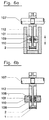
- FIG. 6a shows, especially in the axial direction Towards the center of the drum plate 112 - the brake magnets 101 of both Pages aligned in the axial direction against this drum plate 112 his.
- the two brake magnets 101 which have different poles against the Drum plate 112 can be directed on the inside of a U-shaped Magnet holder 109 may be attached, which is the radially outer end of the Wraps around the winding drum 2, and in particular also in the radial direction is shiftable to change the braking force.
- FIG. 6b also shows from both axial directions against the drum plate 112 directed brake magnets 101, which - however Contrary to the brake magnet 101 in Fig. 6a - a magnetization axis 110 parallel to the drum plate 112, namely in the radial direction of the drum plate, have, and each surrounded by plate-shaped pole pieces 108 are.
- brake magnets 101 which are shown in FIG. 9 are shown in two versions in front and side view. It is can be seen that in both cases the actual brake magnet 101 in Direction of passage through the thickness of the disc is magnetized so that the one Face represents the north pole and the other the south pole.
- FIG. 9 lower embodiment is the south pole and the extent of the disk-shaped magnet by a pot-shaped, one-piece pole piece 108 Covered from soft iron, which in function of the south pole of this magnet is shifted by the field lines outside the south pole through the pole piece 108 through to the open front of the cup-shaped pole piece.
- Fig. 10 show different types of magnetization of disc-shaped Magnets.
- 10a corresponds to the solution according to FIG. Fig. 9, each of which entire face of the disk corresponds to a pole, i.e. north pole or south pole.
- the axial direction of the disk is thus the magnetization axis.
- the magnetization axis is parallel to the disk plane in FIG. 10a '.
- 10c shows a similar magnetization with different sectors Circumferential direction, but here is the disk of the magnet in the direction of passage not magnetized through, but only one of the end faces as a whole magnetized so that this magnetized end face as one in the circumferential direction viewed as a string of differently shaped bar magnets can be considered (sectoral lateral magnetization on a surface).
- FIG. 10d shows the magnet of FIG. 10a, surrounded by a cup-shaped one Pole shoe, as already shown in FIG. 9, lower illustration, and is described.
- Figures 10e-10h show bar magnets.
- the solution in Fig. 10e is the longitudinal direction of the rod the direction of magnetization, i.e. with the north pole on one narrow end and the South Pole on the opposite narrow end.
- the magnetization direction 110 runs transversely to the longitudinal extent of the bar magnet, i.e. with the north pole on one broadside and the South Pole on the other broadside.
- FIG. 10g which is additionally of a U-shaped one Pole 108, preferably made of soft iron, is surrounded, the free ending legs are arranged parallel to the South Pole and North Pole surfaces.
- the winding drum 2 is by means of its axis and bearings 128 in the Side walls of a profile 26 mounted, which serves as a housing.
- the spoke plate is 112 the winding drum 2 in the axial direction centered on the winding cylinder 105 arranged, the outer surface, the winding surface 106, from a tape 1 wound, is shown.
- the spoke plate 112 Opposite two rod-shaped holding magnets 102 arranged with opposite poles against each other, i.e. against the drum plate 112, point.
- the holding magnets 102 are preferably somewhat in the longitudinal direction over the outer surfaces of the winding drum 2.
- the same pair is used of holding magnets 102 on the axis of rotation 107 of the winding drum 2 opposite side also on the radially inner surface of the Cable cylinder 105 arranged.
- the attachment is preferably done by Glue.
- the adjustability of the The air gap between them are the two brake magnets 101 - which in turn are included their magnetization direction arranged parallel to the axis of rotation 107 and with opposite poles are aligned to each other - each in Indentations in the end faces of magnet holders 109 which are directed towards one another arranged, which have an external thread, with the help of which they are in a corresponding, axially running threaded hole through the wall of the Profiles screwed through and thus with regard to the size of the air gap are adjustable.
- the two brake magnets 101 are located to increase the Magnetic force in each case in a cup-shaped pole piece 108, the open side of which each also in the direction of the drum plate 112 and thus on the opposite brake magnets 101 are prepared.
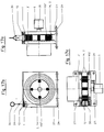
- FIG. 11 a The side view of this solution in FIG. 11 a further shows the possibility of not just one, but several of them distributed along the circumference Brake magnets 101 in magnet holders 109 in the walls of the profile 26 to be arranged, with a minimum distance a between them, to have a negative mutual influence on the brake magnets 110 prevent.
- Fig. 11a also shows that not necessarily a uniform over the circumference Distribution of the brake magnets 101 or magnet holder 109 are available got to.
- the holding magnets 102 are not for reasons of clarity drawn.
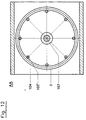
- Fig. 12 shows another front view of the winding drum 2 acc. the line A-A 11.
- FIG Holding magnets 102 By means of a corresponding cut, only those are shown in FIG Holding magnets 102 to recognize the winding drum 2, of which eight pieces in are spaced 45 degrees apart. This representation is meant to make it clear that when selecting sufficiently strong holding magnets 102, these Magnets can serve as combination magnets 102 ', provided that their air gap for adjacent housing, in particular the housing side wall of the profile 26, is correctly dimensioned. In this case it can be completely separate Brake magnets can be dispensed with.
- FIG. 13 shows a solution that differs from FIG. 12 by an additional sliding band 111.
- the one end of the sliding band 111 is at a fixed point 115 attached to the housing near the cable inlet, while the other end is fixed to the housing about an adjustment point 116 on the opposite side of the axis of rotation 107 of the winding drum 2.
- the adjustment point 116 can be displaced both tangentially and radially with respect to the axis 107 of the winding drum 2 , in particular in two mutually perpendicular directions, each transverse to the axis of rotation 107.
- the loose or completely missing contact between the sliding band 111 and the outside of the rope winding can be adjusted to intensify or loosen the contact with the aim of a To prevent "rising", ie radial lifting, if the combination magnets 102 'or the holding magnets 102 prove to be insufficient for this.
- the rising can already be prevented by essentially no contact between the sliding band 111 and the outside of the measuring cable winding is present, since this contact only occurs when the band undesirably rises in the radial direction to the outside.
- the possible distance between the outer surface of the cable winding and the inner surface of the retaining band must be set as small as possible, ideally approximately zero .
- Fig. 13a shows a solution in which the sliding band 111 does not loosely around the rope-wound drum is laid around, but as a covering on one Sliding shoe 114 is located, the contour of the winding drum 2 facing The outer contour of the wound winding drum 2 corresponds.
- the shoe 114 extends around 90 ° around the outer circumferential surface of the winding drum 2 around, in the winding direction in the to the run-up point of the Winding drum adjoining segment.
- the slide shoe 114 is on the housing 104 attached, in particular screwed and positioned so that its out Sliding tape 111 existing covering the desired contact to the outer surface of the Has rope winding of the winding drum 2, as the sectional view B-B shows.
- FIGS. 1 and 3 additionally shows - compared to the other views of FIGS. 1 and 3 - also already brake magnets 101 in the housing plates 15 of the housing, which are directed against the end disks 14 of the winding drum 2.
- Fig. 14 also shows a variant in the three views, also in the such brake magnets 101 are present, and also diametrically opposite at the same height on the housing.
- the housing is there - in Contrary to the solution of Figures 1-3 - from a section of a box profile 23, the upper and lower, open end faces by end plates 24 are closed, the lower one protrudes laterally beyond the profile 26 and as Attachment to the environment is used.
- the solution according to FIG. 15 differs from that according to FIG. 14 characterized in that the flat spiral spring 3 is not axially offset from the winding drum 2 in is arranged in a separate housing, but coaxially inside this Winding drum. For this purpose it is inside the cylindrical Winding surface of the winding drum 2, the face of the end disks 14th is limited, a recess open at least to one end, in which the shaft of the angle encoder 5 extends centrally.
- the flat spiral spring 3 is thereby arranged between them, which on the one hand with attachment points 26a, 26b with a fixed point of Housing and on the other hand is connected to the winding drum. This will the entire axial installation space for a separate spring housing 3 'is saved.
- the solution of FIG. 16 differs from that of FIG. 15 in two points:
- the magnets are designed as combination magnets 102 ', and thus fulfill the double function of braking the winding drum 2 on the one hand and on the other hand, to pull the tape 1 radially inwards onto the winding drum.
- the combination magnets 102 ' are evenly distributed over the circumference arranged inside the winding drum 2, namely within its cylindrical Winding surface 105 arranged.
- the combination magnets 102 ' extend thereby axially over the entire width of the winding drum 2 from one to the other of the two end plates 14, with the direction of magnetization parallel to Rotation axis of the winding drum 2.
- the second difference is the attachment of the angle encoder 5.
- This has an outwardly projecting hollow shaft, which on the shaft 4 of the Winding drum 2 plugged on and connected to it in a rotationally fixed manner.
- a torque arm 27 'between the non-rotating part of the angle encoder 5 and the box section 23 as the housing consists of a bent sheet metal part, which is bendable in all directions transverse to the axis of rotation 11 and thus at the same time compensating for an angular misalignment between rotary encoder 5 and housing serves.
- the torque arm 27 ' surrounds the shaft 4 in an annular manner and is on two diametrically opposite sides with the Housing, and on two other diagonally opposite sides with the Angle of rotation encoder 5 screwed. 17 corresponds in terms of the presence and location of the combination magnets 102 'of the solution 16, but has the conventional torque arm 27 14, namely the one-sided projecting from the shaft 4 and with the Bolted support.
- FIG. 18 differs from that of FIG. 14 in that that as a housing section of a box section with two side by side lying chambers, each closed in cross section, is used, which is arranged in the horizontal direction and the bottom plate protrudes laterally outwards and for attachment to the environment can be used.
- End faces which are then open on both sides to the side, are covered by corresponding End plates 24 'completed. It sits on one outer surface of the Box profile 23 'of the rotary encoder 5 while on the other outer surface the spring housing 3 'is fastened with the flat spiral spring 3 located therein.
- a winding drum 2 with combination magnets 102 'as in the solutions according to the Figures 16 and 17 is in the chamber adjacent to the spring housing 3 ' housed for winding the tape 1.
- a coupling 25 is arranged, which the shaft 4, on which the winding drum 2 and the torsion spring 3 are attached, with the Shaft journal of the rotary angle encoder 5 is non-rotatable and compensates for angular misalignments connects.
- the end plates 24, 24 ' are screwed to the box profiles 23, 23' in each case via to the inner chambers incorporated into the box profiles 23 ' open and undercut screw channels, into which from the front the screws on the end plates are screwed in in a self-tapping manner can.
Landscapes
- Physics & Mathematics (AREA)
- General Physics & Mathematics (AREA)
- Storing, Repeated Paying-Out, And Re-Storing Of Elongated Articles (AREA)
- Tape Measures (AREA)
- Force Measurement Appropriate To Specific Purposes (AREA)
Abstract
Description

- Fig. 1:
- eine Schnittdarstellung durch die Rotationsachse,
- Fig. 2:
- eine Aufsicht auf den Wegsensor quer zur Rotationsachse,
- Fig. 3:
- eine Aufsicht in Blickrichtung der Rotationsachse,
- Fig. 4:
- eine Hubvorrichtung in Seitenansicht,
- Fig. 5:
- einen Horizontalschnitt durch diese Hubvorrichtung der Fig. 4,
- Fig. 6:
- die Bremsmagnete im Gehäuse,
- Fig. 7:
- die Bremsmagnete in der Wickeltrommel,
- Fig. 8:
- eine Frontansicht der Wickeltrommel der Fig. 7,
- Fig. 9:
- Detaildarstellungen der Bremsmagnete,
- Fig. 10:
- unterschiedlich magnetisierte Magnete,
- Fig. 11:
- einen Schnitt durch eine weitere Ausführungsform eines Zugelement-Wegsensors,
- Fig. 12:
- eine Ansicht der Wickeltrommel aus Fig. 11,
- Fig. 13:
- eine weiter Bauform des Zugelementwegsensors,
- Fig. 14:
- eine erste Lösung mit Bremsmagneten,
- Fig. 15:
- eine zweite Lösung mit Bremsmagneten und einer Feder innerhalb der Wickeltrommel,
- Fig. 16:
- eine dritte Lösung mit Bremsmagneten und Haltemagneten,
- Fig. 17:
- eine vierte Lösung mit Kombimagneten, und
- Fig. 18:
- eine fünfte Lösung mit Kombimagneten und Kupplung.
- bei den Haltemagneten das durch die Magnete beaufschlagte Band 1 aus einem magnetisierbaren Material bestehen muß, bzw.
- bei den Bremsmagneten das beeinflußte Bauteil (also bei Anordnung der Bremsmagnete an der Wickeltrommel das Gehäuse oder bei Anordnung der Bremsmagneten am Gehäuse die Wickeltrommel (wenigstens im beeinflußten Bereich) aus elektrisch leitfähigem Material bestehen muß oder beschichtet sein muß.
- L
- Last
- 1
- Band
- 2
- Wickeltrommel
- 3
- Flachspiralfeder
- 4
- Welle
- 5
- Drehwinkelgeber
- 6
- Vorspanneinheit
- 7
- Hubeinheit
- 8
- Schlitten
- 9
- Seilaufsatz
- 10
- Längsrichtung
- 11
- Rotationsachse
- 13
- Trommelkern
- 14
- Stirnscheiben
- 15
- Gehäuseplatte
- 16
- Gehäusebolzen
- 17
- Gebäudedecke
- 18
- Gleitscheibe
- 19
- Lagerschild
- 20
- Toleranzring
- 22a, 22b
- Flanken
- 23, 23'
- Kastenprofil
- 24, 24'
- Endplatte
- 25
- Kupplung
- 26
- Profil
- 27
- Blechgabel
- 28
- Drehmoment-Stützbolzen
- 31
- Adapter
- 32
- Motor
- 101
- Bremsmagnet
- 102
- Haltemagnet
- 102'
- Kombimagnete
- 103
- Einwirkbereich
- 104
- Gehäuse
- 105
- Wickelzylinder
- 106
- Wickelfläche
- 107
- Achse
- 108
- Polschuh
- 109
- Verstellschraube und Magnethalter
- 110
- Magnetisierungsachse
- 111
- Gleitband
- 112
- Trommelplatte
- 113
- Kontaktschutz
- 114
- Gleitschuh
- 115
- Festpunkt
- 116
- Verstellpunkt
- 128
- Lager
- 130
- Gleitrolle
Claims (18)
- Zugelement-Wegsensor miteiner Zugelement-Wickeltrommel (2)einer damit wirkverbundenen Vorspanneinheit zum Vorspannen der Wickeltrommel (2) in die Aufwickelrichtung,einer Bestimmungseinheit zum Bestimmen der von der Wickeltrommel (2) abgezogenen Länge des Zugelementes
dadurch gekennzeichnet, daß
das Zugelement auf der Wickeltrommel (2) in einer einzigen Radialebene der Wickeltrommel (2) spiralig in mehreren Lagen übereinander gewickelt ist. - Wegsensor nach Anspruch 1,
dadurch gekennzeichnet, daß
das Zugelement ein Band (1) ist, dessen Querschnitt in axialer Richtung der Rotationsachse der Wickeltrommel (2) wesentlich größer, insbesondere mindestens 10-fach so groß, dimensioniert ist wie in Querrichtung hierzu, und insbesondere das Band (1) in Längsrichtung nur sehr gering, insbesondere überhaupt nicht dehnbar ist, und insbesondere das Band (1) ein Metallband ist. - Wegsensor nach einem der vorhergehenden Ansprüche,
dadurch gekennzeichnet, daß
die Vorspanneinheit eine Flachspiralfeder (3) ist, die insbesondere koaxial zur insbesondere in der Wickeltrommel (2) angeordnet ist. - Wegsensor nach einem der vorhergehenden Ansprüche,
dadurch gekennzeichnet, daß
die Bestimmungseinheit ein Drehwinkelgeber (5) ist, der mit der Wickeltrommel (2) wirkverbunden, insbesondere drehtest verbunden, ist und die zurückgelegten Winkelelemente der Wickeltrommel (2) ermittelt und an eine Auswerteelektronik meldet, wobei die Auswerteelektronik aus den zurückgelegten Winkelsegmenten die abgezogene Länge des Zugelementes ermittelt unter Berücksichtigung der sich ändernden Wicklungslänge einer Wicklung des Zugelementes je nach Anzahl der Wicklungslagen auf der Wicklungstrommel (2), und insbesondere die Bestimmungseinheit eine am Gehäuse der Wickeltrommel (2) angeordnete insbesondere elektrische Abtasteinheit ist und das Zugelement in Längsrichtung abwechselnde gleichlange Abschnitte mit wechselnden Eigenschaften, die elektrisch detektierbar sind, aufweist, insbesondere abschnittsweise unterschiedlich magnetisierbar ist, und insbesondere die Bestimmungseinheit eine Einheit zum Aussenden von Wellen, insbesondere von mechanischen, insbesondere mechanisch-elastischen Wellen und/oder Schallwellen, entlang des abgewickelten Teiles des Zugelementes umfaßt sowie eine Zeitmeßeinrichtung zum Bestimmen der Zeit zwischen Aussendung der Wellen und Eintreffen der Welle auf dem Rückweg vom freien Ende des Zugelementes. - Wegsensor nach einem der vorhergehenden Ansprüche,
dadurch gekennzeichnet, daß
die Berücksichtigung der variablen Wicklungslänge selbstlemend erfolgt insbesondere durch einmaliges oder mehrmaliges, teilweise sogar vollständiges, Abziehen einer definierten Länge des Zugelementes von der Wicklungstrommel. - Hubvorrichtung zum Heben einer Last mit wenigstens zwei Hubeinheiten und wenigstens einem Wegsensor, wobei jede Hubeinheiteine Zugelement-Wickeltrommel (2),eine damit wirkverbundene Vorspanneinheit zum Vorspannen der Wickeltrommel (2) in die Aufwickelrichtung,einen die Wickeltrommel (2) wenigstens in der Aufwickelrichtung antreibenden Motor (32) umfaßt, unddie Hubvorrichtungen mit nach unten weisenden freien Enden der Zugelemente angeordnet sind
dadurch gekennzeichnet, daß
wenigstens eine der Hubvorrichtungen mit einer Bestimmungseinheit zum Bestimmen der von der Wickeltrommel (2) abgezogenen Länge des Zugelementes ausgestattet ist und alle Zugelemente an der selben Last (L) angreifen. - Hubvorrichtung nach Anspruch 6,
dadurch gekennzeichnet, daß
jede der Hubeinheiten mit einer Bestimmungseinheit ausgestattet ist. - Hubvorrichtung nach Anspruch 6 oder 7,
dadurch gekennzeichnet, daß
das Zugelement auf der Wickeltrommel (2) in einer einzigen Radialebene der Wickeltrommel (2) spiralig in mehreren Lagen übereinander gewickelt ist, und insbesondere das Zugelement ein Band (1) ist, dessen Querschnitt in axialer Richtung der Rotationsachse der Wickeltrommel (2) wesentlich größer, insbesondere mindestens 10-fach so groß, dimensioniert ist wie in Querrichtung hierzu. - Hubvorrichtung nach einem der vorhergehenden Ansprüche,
dadurch gekennzeichnet, daß
an der Last (L) zwei Bänder (1) im Abstand zueinander und mit den Haupterstreckungsrichtungen ihrer Querschnitte parallel zueinander angreifen, und insbesondere an der Last vier Bänder (1), deren Haupterstreckungsrichtung der Querschnitte im Viereck zueinander liegen, angreifen, und insbesondere der Motor (32) und/oder ein Adapter (31), an dem die freien Enden der Zugelemente angreifen, gleichzeitig als Spanneinrichtung zum Vorspannen der Wickelrolle (2) in die Aufwickelrichtung dient. - Zugelement-Wegsensor miteiner Wickeltrommel (2) zum Aufwickeln des Bandes (1) auf der äußeren Wickelfläche (106) des Wickelzylinders (105) der Wickeltrommel (2), undeinem Gehäuse, in welchem die Wickeltrommel (2) gelagert ist,
dadurch gekennzeichnet, daßwenigstens ein Bremsmagnet (101) an einem nicht mit der Wickeltrommel (2) mitdrehenden Punkt so angeordnet ist, daß er berührungslos magnetisch auf die Wickeltrommel (2) an einem exzentrischen Einwirkbereich (103') gegen die Drehrichtung bremsend einwirkt, unddie Wickeltrommel (2) wenigstens im Einwirkbereich (103') aus elektrisch leitfähigem Material besteht, und insbesondere der Bremsmagnet (101) am Gehäuse (104) angeordnet ist. - Zugelement-Wegsensor miteiner Wickeltrommel (2) zum Aufwickeln des Bandes (1) auf der äußeren Wickelfläche (106) des Wickelzylinders (105) der Wickeltrommel (2), undeinem Gehäuse, in welchem die Wickeltrommel (2) gelagert ist,
dadurch gekennzeichnet, daßwenigstens ein Bremsmagnet (101) an der Wickeltrommel (2) exzentrisch so angeordnet ist, daß er berührungslos magnetisch auf das Gehäuse in Drehrichtung bremsend einwirkt, unddas Gehäuse (4) wenigstens im Einwirkbereich (103') aus elektrisch leitfähigem Material besteht. - Zugelement-Wegsensor miteiner Wickeltrommel (2) zum Aufwickeln des Bandes (1) auf der äußeren Wickelfläche (106) des Wickelzylinders (105) der Wickeltrommel (2), undeinem Gehäuse, in welchem die Wickeltrommel (2) gelagert ist,
dadurch gekennzeichnet, daßan der Wickeltrommel (2) radial innerhalb der Mittelfläche (106) des Wickelzylinders (105) wenigstens ein Haltemagnet (102) angeordnet ist zum Halten des Bandes (1) radial nach innen an der Wickelfläche (106), unddas Band (1) aus magnetisierbarem Material besteht. - Zugelement-Wegsensor miteiner Wickeltrommel (2) zum Aufwickeln des Bandes (1) auf der äußeren Wickelfläche (106) des Wickelzylinders (105) der Wickeltrommel (2), undeinem Gehäuse, in welchem die Wickeltrommel (2) gelagert ist,
dadurch gekennzeichnet, daß
um wenigstens einen Teil des Außenumfanges der ganz oder teilweise mit Band (1) beweglichen Wickelfläche (106) ein Gleitband (111), insbesondere ein Band aus Textilmaterial, insbesondere ein Gleitband oder ein Band aus anderem gleitfähigen, nicht abrasiven Material, in geringem Abstand und/oder an dem Außenumfang der Bewicklung mit Band schleifend herumgeführt ist und der Abstand, bzw. Anpreßdruck des Bandes gegen die Bewicklung mit Band (1) einstellbar ist. - Zugelement-Wegsensor nach einem der vorhergehenden Zugelement-Ansprüche,
dadurch gekennzeichnet, daß
der an der Wickeltrommel (2) angeordnete mindestens eine Bremsmagnet (101) und/oder Haltemagnete (102) jeweils gleichmäßig über den Umfang verteilt, insbesondere paarweise zur Vermeidung von Unwucht an der Wickeltrommel angeordnet sind, und insbesondere die Bremsmagnete (101) mit möglichst großem Abstand zur Rotationsachse (107) der Wickeltrommel (2), insbesondere nahe am Außenumfang der Wickeltrommel (105), angeordnet sind, die Bremsmagnete (101) und/oder die Haltemagnete (102) Permanentmagnete sind. - Zugelement-Wegsensor nach einem der vorhergehenden Zugelement-Ansprüche,
dadurch gekennzeichnet, daß
die Haltemagnete mit ihrer Magnetisierungsachse (110) parallel zur Rotationsachse (107) der Wickeltrommel (2) angeordnet sind, und insbesondere die Bremsmagnete (101) mit ihrer Magnetisierungsachse (110) parallel zur Rotationsachse (107) der Wickeltrommel (2) angeordnet und entgegengesetzt gepolt sind, die Bremsmagnete (101) mit Polschuh-Stücken radial innerhalb sowie radial außerhalb der Magnetisierungsachse (110), insbesondere mit einem tropfförmigen Polschuh-Stück (108), welches nur zu dem beeinflussenden Bauteil hin offen ist, ausgestattet ist. - Zugelement-Wegsensor nach einem der vorhergehenden Zugelement-Ansprüche,
dadurch gekennzeichnet, daß
die Bremsmagnete (101) und/oder die Haltemagnete (102) in einem Magnethalter (109) aufgenommen sind, dessen Position in axialer Richtung gegenüber dem zu beeinflussenden Bauteil einstellbar, insbesondere stufenlos einstellbar, ist, und insbesondere der Magnethalter (109) ein Gewindebolzen ist, an dessen einer Stirnseite der Bremsmagnet (101) und/oder Haltemagnet (102) gegen das zu beeinflussende Bauteil hin gerichtet angeordnet ist. - Zugelement-Wegsensor nach einem der vorhergehenden Zugelement-Ansprüche,
dadurch gekennzeichnet, daß
als Bremsmagnete (101) beidseits der Wickeltrommel (2) gegenüberliegend und in Längsrichtung mit entgegengesetzten Polen gegeneinanderweisende Magnete in Längsrichtung fluchtend angeordnet sind, und insbesondere als Bremsmagnete (101) scheibenförmige Magnete verwendet werden, deren Magnetisierungsachse (110) der Dicke des scheibenförmigen Magneten entspricht, und insbesondere als Bremsmagnete (101) scheibenförmige Magnete verwendet werden, die in Sektoren unterteilt sind, wobei die einzelnen Sektoren als Einzelmagnete wirken, deren Magnetisierungsachsen (10) jeweils der Dicke des scheibenförmigen Magneten entsprechen, wobei die Polung der einzelnen Sektoren entlang des Umfanges wechselt, und insbesondere als Bremsmagnete (101) scheibenförmige Magnete verwendet werden, bei denen nur eine der Hauptflächen magnetisiert ist durch sektorenförmig abwechselnde Magnetisierung in Umfangsrichtung. - Zugelement-Wegsensor nach einem der vorhergehenden Zugelement-Ansprüche,
dadurch gekennzeichnet, daß
der bzw. die. Bremsmagnete (101) und der bzw. die Haltemagnete (102) gemäß einem der vorhergehenden Ansprüche in jeweils einem Kombimagnet funktionsvereinigt sind.
Applications Claiming Priority (2)
| Application Number | Priority Date | Filing Date | Title |
|---|---|---|---|
| DE19859474 | 1998-12-22 | ||
| DE19859474A DE19859474C2 (de) | 1998-12-22 | 1998-12-22 | Zugelement-Wegsensor |
Publications (2)
| Publication Number | Publication Date |
|---|---|
| EP1013594A2 true EP1013594A2 (de) | 2000-06-28 |
| EP1013594A3 EP1013594A3 (de) | 2001-06-13 |
Family
ID=7892269
Family Applications (1)
| Application Number | Title | Priority Date | Filing Date |
|---|---|---|---|
| EP99125624A Withdrawn EP1013594A3 (de) | 1998-12-22 | 1999-12-22 | Zugelement-Wegesensor |
Country Status (3)
| Country | Link |
|---|---|
| US (1) | US6430836B1 (de) |
| EP (1) | EP1013594A3 (de) |
| DE (1) | DE19859474C2 (de) |
Cited By (1)
| Publication number | Priority date | Publication date | Assignee | Title |
|---|---|---|---|---|
| GB2385423A (en) * | 2002-01-16 | 2003-08-20 | Ctex Seat Comfort Ltd | A component position indicating system |
Families Citing this family (4)
| Publication number | Priority date | Publication date | Assignee | Title |
|---|---|---|---|---|
| US7007386B1 (en) | 2002-12-20 | 2006-03-07 | General Sullivan Group, Inc. | Light duty bearing assembly |
| DE102004044117B4 (de) * | 2004-09-11 | 2008-08-14 | Fernsteuergeräte Kurt Oelsch GmbH | Seillängengeber mit Seilbremse |
| CN112723207B (zh) * | 2019-10-14 | 2022-06-28 | 广州彩熠灯光股份有限公司 | 盘式卷扬机输出位置的定位系统、方法及盘式卷扬机 |
| CN114315118B (zh) * | 2021-12-28 | 2022-08-23 | 华中科技大学 | 一种多品种玻璃激光切孔孔位干涉自主规避方法 |
Family Cites Families (12)
| Publication number | Priority date | Publication date | Assignee | Title |
|---|---|---|---|---|
| FR1271129A (fr) * | 1960-07-25 | 1961-09-08 | Desauge & Lair | Perfectionnement aux appareils de mesure à ruban |
| US3678583A (en) * | 1971-01-18 | 1972-07-25 | Power Drive Corp | Work positioner |
| FI54789C (fi) * | 1972-03-15 | 1979-03-12 | Kone Oy | Anordning vid en kran |
| US4205453A (en) * | 1975-03-17 | 1980-06-03 | Steele Richard W | Towing hitch alignment director |
| JPS59114401A (ja) * | 1982-12-21 | 1984-07-02 | Taisei Corp | 距離自動測定装置 |
| DE8801109U1 (de) | 1988-01-29 | 1988-06-01 | Fernsteuergeräte Kurt Oelsch GmbH, 12347 Berlin | Seillängengeber |
| DE3910873A1 (de) * | 1989-04-04 | 1990-10-18 | Stahl R Foerdertech Gmbh | Positionsmessvorrichtung fuer kran- und elektrohaengebahnen |
| DE3912585A1 (de) * | 1989-04-17 | 1990-10-18 | Siemens Ag | Einrichtung zur weg-istwerterfassung von fahrstrecken bei schienengebundenen kranen |
| JPH05270735A (ja) * | 1992-03-30 | 1993-10-19 | Mitsubishi Electric Corp | 巻線装置 |
| DE19520388C2 (de) * | 1995-06-02 | 1997-04-10 | Asm Automation Sensorik Messte | Meßseil-Wegsensor mit schalenförmigem Gehäuse |
| DE29509188U1 (de) * | 1995-06-02 | 1995-08-17 | ASM Automation Sensorik Meßtechnik GmbH, 82008 Unterhaching | Meßseil-Wegsensor mit schalenförmigem Gehäuse |
| US6269547B1 (en) * | 1999-10-04 | 2001-08-07 | Hsu-Chen Chuang | Digital cable extension transducer |
-
1998
- 1998-12-22 DE DE19859474A patent/DE19859474C2/de not_active Expired - Fee Related
-
1999
- 1999-12-22 US US09/468,925 patent/US6430836B1/en not_active Expired - Lifetime
- 1999-12-22 EP EP99125624A patent/EP1013594A3/de not_active Withdrawn
Cited By (3)
| Publication number | Priority date | Publication date | Assignee | Title |
|---|---|---|---|---|
| GB2385423A (en) * | 2002-01-16 | 2003-08-20 | Ctex Seat Comfort Ltd | A component position indicating system |
| US6768321B2 (en) | 2002-01-16 | 2004-07-27 | Ctex Seat Comfort Limited | Component position indicating apparatus |
| GB2385423B (en) * | 2002-01-16 | 2005-12-07 | Ctex Seat Comfort Ltd | Component position indicating apparatus |
Also Published As
| Publication number | Publication date |
|---|---|
| US6430836B1 (en) | 2002-08-13 |
| DE19859474A1 (de) | 2000-07-06 |
| DE19859474C2 (de) | 2001-04-19 |
| EP1013594A3 (de) | 2001-06-13 |
Similar Documents
| Publication | Publication Date | Title |
|---|---|---|
| DE19859445C2 (de) | Meßseil-Wegsensor mit einem Längsantrieb für die Seiltrommel | |
| EP0503315B1 (de) | Wickelvorrichtung zum Auf- und Abwickeln einer Leitung | |
| EP1478900B1 (de) | Getriebe sowie mit diesem getriebe ausgestatteter drehgeber | |
| EP1979716B2 (de) | Messanordnung mit magnet | |
| EP1014032B1 (de) | Messseil-Wegsensor | |
| EP2653428A1 (de) | Seillängengeber | |
| DE2937962A1 (de) | Gleichstommotor | |
| EP0671008A1 (de) | Vorrichtung zur messung von drehbewegungen | |
| DE19859474C2 (de) | Zugelement-Wegsensor | |
| EP1550838A1 (de) | Messseil-Wegsensor mit Feder in der Seiltrommel | |
| DE4104250A1 (de) | Antrieb und lagerung fuer einen oe-spinnrotor | |
| EP3884241A1 (de) | Messwertgeber für fahrtreppenwelle | |
| DE202021102814U1 (de) | Vorrichtung zur Dämpfung einer Einzugsgeschwindigkeit und Gewichtsausgleicher mit einer solchen | |
| DE112018001530T5 (de) | Ölpumpe | |
| EP0412304B1 (de) | Geber zum Messen mechanischer Kräfte mit Messbandbefestigung | |
| DE4413717C2 (de) | Hubwerk | |
| EP0799423A1 (de) | Vorrichtung zur bestimmung von drehbewegungen | |
| DE60004738T2 (de) | Vorrichtung zum Messen der Parameter beim Öffnen eines Teils und Kalibriermethode für diese Vorrichtung | |
| EP1028081A2 (de) | Aufzugsantrieb mit elektrischem Antriebsmotor | |
| DE102024118260B3 (de) | Rollenförmiger Wälzkörper zur Verwendung in einem Wälzlager | |
| EP1364441B1 (de) | Elektromagnetische antriebsvorrichtung | |
| WO2009000239A1 (de) | Bandrolle eines spiralig auf- und abwickelbaren bandes | |
| DE102016202022B4 (de) | Drehvorrichtung und Verfahren zum Drehen | |
| DE1911486B2 (de) | Elektrischer drehzahlgeber | |
| DE202021004357U1 (de) | Hebezeug für Brückenkräne und Portalkräne sowie Kran mit einem solchen Hebezeug |
Legal Events
| Date | Code | Title | Description |
|---|---|---|---|
| PUAI | Public reference made under article 153(3) epc to a published international application that has entered the european phase |
Free format text: ORIGINAL CODE: 0009012 |
|
| AK | Designated contracting states |
Kind code of ref document: A2 Designated state(s): DE ES FR GB IT |
|
| AX | Request for extension of the european patent |
Free format text: AL;LT;LV;MK;RO;SI |
|
| PUAL | Search report despatched |
Free format text: ORIGINAL CODE: 0009013 |
|
| AK | Designated contracting states |
Kind code of ref document: A3 Designated state(s): AT BE CH CY DE DK ES FI FR GB GR IE IT LI LU MC NL PT SE |
|
| AX | Request for extension of the european patent |
Free format text: AL;LT;LV;MK;RO;SI |
|
| 17P | Request for examination filed |
Effective date: 20010619 |
|
| AKX | Designation fees paid |
Free format text: DE ES FR GB IT |
|
| RAP1 | Party data changed (applicant data changed or rights of an application transferred) |
Owner name: ASM AUTOMATION SENSORIK MESSTECHNIK GMBH |
|
| STAA | Information on the status of an ep patent application or granted ep patent |
Free format text: STATUS: THE APPLICATION HAS BEEN WITHDRAWN |
|
| 18W | Application withdrawn |
Effective date: 20090408 |