EP1013743A1 - Fluidkatalytisch Krachverfahren - Google Patents
Fluidkatalytisch Krachverfahren Download PDFInfo
- Publication number
- EP1013743A1 EP1013743A1 EP98310512A EP98310512A EP1013743A1 EP 1013743 A1 EP1013743 A1 EP 1013743A1 EP 98310512 A EP98310512 A EP 98310512A EP 98310512 A EP98310512 A EP 98310512A EP 1013743 A1 EP1013743 A1 EP 1013743A1
- Authority
- EP
- European Patent Office
- Prior art keywords
- catalyst
- adsorbent
- riser
- separator
- burner
- Prior art date
- Legal status (The legal status is an assumption and is not a legal conclusion. Google has not performed a legal analysis and makes no representation as to the accuracy of the status listed.)
- Granted
Links
- 238000000034 method Methods 0.000 title claims description 37
- 230000008569 process Effects 0.000 title claims description 35
- 238000004231 fluid catalytic cracking Methods 0.000 title abstract description 5
- 239000003054 catalyst Substances 0.000 claims abstract description 184
- 239000003463 adsorbent Substances 0.000 claims abstract description 147
- 239000002245 particle Substances 0.000 claims abstract description 103
- 239000000571 coke Substances 0.000 claims abstract description 61
- 229910052720 vanadium Inorganic materials 0.000 claims abstract description 47
- LEONUFNNVUYDNQ-UHFFFAOYSA-N vanadium atom Chemical compound [V] LEONUFNNVUYDNQ-UHFFFAOYSA-N 0.000 claims abstract description 47
- 229930195733 hydrocarbon Natural products 0.000 claims abstract description 27
- 150000002430 hydrocarbons Chemical class 0.000 claims abstract description 27
- 239000000203 mixture Substances 0.000 claims abstract description 25
- PXHVJJICTQNCMI-UHFFFAOYSA-N Nickel Chemical compound [Ni] PXHVJJICTQNCMI-UHFFFAOYSA-N 0.000 claims abstract description 24
- 229910052751 metal Inorganic materials 0.000 claims abstract description 22
- 239000002184 metal Substances 0.000 claims abstract description 22
- 239000011329 calcined coke Substances 0.000 claims abstract description 21
- 150000002739 metals Chemical class 0.000 claims abstract description 15
- 238000000926 separation method Methods 0.000 claims abstract description 15
- 238000004523 catalytic cracking Methods 0.000 claims abstract description 14
- 229910052759 nickel Inorganic materials 0.000 claims abstract description 12
- 239000012535 impurity Substances 0.000 claims abstract description 4
- 239000004215 Carbon black (E152) Substances 0.000 claims description 16
- 238000006243 chemical reaction Methods 0.000 claims description 12
- 238000002485 combustion reaction Methods 0.000 claims description 12
- 239000007789 gas Substances 0.000 claims description 12
- 231100000614 poison Toxicity 0.000 claims description 10
- 238000004891 communication Methods 0.000 claims description 8
- 239000002574 poison Substances 0.000 claims description 8
- IJGRMHOSHXDMSA-UHFFFAOYSA-N Atomic nitrogen Chemical compound N#N IJGRMHOSHXDMSA-UHFFFAOYSA-N 0.000 claims description 6
- 230000002378 acidificating effect Effects 0.000 claims description 6
- 238000005336 cracking Methods 0.000 claims description 6
- 230000008929 regeneration Effects 0.000 claims description 6
- 238000011069 regeneration method Methods 0.000 claims description 6
- 239000010457 zeolite Substances 0.000 claims description 6
- 238000010926 purge Methods 0.000 claims description 5
- 229910021536 Zeolite Inorganic materials 0.000 claims description 4
- PNEYBMLMFCGWSK-UHFFFAOYSA-N aluminium oxide Inorganic materials [O-2].[O-2].[O-2].[Al+3].[Al+3] PNEYBMLMFCGWSK-UHFFFAOYSA-N 0.000 claims description 4
- HNPSIPDUKPIQMN-UHFFFAOYSA-N dioxosilane;oxo(oxoalumanyloxy)alumane Chemical compound O=[Si]=O.O=[Al]O[Al]=O HNPSIPDUKPIQMN-UHFFFAOYSA-N 0.000 claims description 4
- 238000002347 injection Methods 0.000 claims description 3
- 239000007924 injection Substances 0.000 claims description 3
- 229910052757 nitrogen Inorganic materials 0.000 claims description 3
- NLYAJNPCOHFWQQ-UHFFFAOYSA-N kaolin Chemical compound O.O.O=[Al]O[Si](=O)O[Si](=O)O[Al]=O NLYAJNPCOHFWQQ-UHFFFAOYSA-N 0.000 claims description 2
- -1 nitrogen Chemical compound 0.000 claims description 2
- 230000001172 regenerating effect Effects 0.000 claims description 2
- 229910052622 kaolinite Inorganic materials 0.000 claims 1
- 230000007420 reactivation Effects 0.000 claims 1
- 239000007787 solid Substances 0.000 abstract description 13
- 238000012545 processing Methods 0.000 abstract description 12
- 238000001816 cooling Methods 0.000 abstract description 6
- 230000009849 deactivation Effects 0.000 abstract description 3
- 239000003208 petroleum Substances 0.000 abstract description 3
- 239000008247 solid mixture Substances 0.000 abstract description 3
- 229910044991 metal oxide Inorganic materials 0.000 abstract 1
- 150000004706 metal oxides Chemical class 0.000 abstract 1
- 238000005204 segregation Methods 0.000 description 15
- 230000000694 effects Effects 0.000 description 11
- UGFAIRIUMAVXCW-UHFFFAOYSA-N Carbon monoxide Chemical compound [O+]#[C-] UGFAIRIUMAVXCW-UHFFFAOYSA-N 0.000 description 10
- VYPSYNLAJGMNEJ-UHFFFAOYSA-N Silicium dioxide Chemical compound O=[Si]=O VYPSYNLAJGMNEJ-UHFFFAOYSA-N 0.000 description 10
- 239000003546 flue gas Substances 0.000 description 10
- 239000000654 additive Substances 0.000 description 8
- 230000000996 additive effect Effects 0.000 description 8
- 230000008901 benefit Effects 0.000 description 8
- 239000004576 sand Substances 0.000 description 6
- QVGXLLKOCUKJST-UHFFFAOYSA-N atomic oxygen Chemical compound [O] QVGXLLKOCUKJST-UHFFFAOYSA-N 0.000 description 5
- 238000000151 deposition Methods 0.000 description 5
- 229910052760 oxygen Inorganic materials 0.000 description 5
- 239000001301 oxygen Substances 0.000 description 5
- 230000008021 deposition Effects 0.000 description 4
- 238000013461 design Methods 0.000 description 4
- 239000011148 porous material Substances 0.000 description 4
- NINIDFKCEFEMDL-UHFFFAOYSA-N Sulfur Chemical compound [S] NINIDFKCEFEMDL-UHFFFAOYSA-N 0.000 description 3
- 238000009826 distribution Methods 0.000 description 3
- 238000005516 engineering process Methods 0.000 description 3
- 230000020169 heat generation Effects 0.000 description 3
- 238000002156 mixing Methods 0.000 description 3
- 238000002161 passivation Methods 0.000 description 3
- JTJMJGYZQZDUJJ-UHFFFAOYSA-N phencyclidine Chemical class C1CCCCN1C1(C=2C=CC=CC=2)CCCCC1 JTJMJGYZQZDUJJ-UHFFFAOYSA-N 0.000 description 3
- DGAQECJNVWCQMB-PUAWFVPOSA-M Ilexoside XXIX Chemical compound C[C@@H]1CC[C@@]2(CC[C@@]3(C(=CC[C@H]4[C@]3(CC[C@@H]5[C@@]4(CC[C@@H](C5(C)C)OS(=O)(=O)[O-])C)C)[C@@H]2[C@]1(C)O)C)C(=O)O[C@H]6[C@@H]([C@H]([C@@H]([C@H](O6)CO)O)O)O.[Na+] DGAQECJNVWCQMB-PUAWFVPOSA-M 0.000 description 2
- XEEYBQQBJWHFJM-UHFFFAOYSA-N Iron Chemical compound [Fe] XEEYBQQBJWHFJM-UHFFFAOYSA-N 0.000 description 2
- CPLXHLVBOLITMK-UHFFFAOYSA-N Magnesium oxide Chemical compound [Mg]=O CPLXHLVBOLITMK-UHFFFAOYSA-N 0.000 description 2
- 238000000889 atomisation Methods 0.000 description 2
- 238000009835 boiling Methods 0.000 description 2
- 238000001354 calcination Methods 0.000 description 2
- 239000011362 coarse particle Substances 0.000 description 2
- 239000002131 composite material Substances 0.000 description 2
- 230000003111 delayed effect Effects 0.000 description 2
- 230000009977 dual effect Effects 0.000 description 2
- 238000005470 impregnation Methods 0.000 description 2
- 230000006872 improvement Effects 0.000 description 2
- 239000000463 material Substances 0.000 description 2
- 239000004005 microsphere Substances 0.000 description 2
- 229910017464 nitrogen compound Inorganic materials 0.000 description 2
- 150000002830 nitrogen compounds Chemical class 0.000 description 2
- 230000007096 poisonous effect Effects 0.000 description 2
- 229910052761 rare earth metal Inorganic materials 0.000 description 2
- 150000002910 rare earth metals Chemical group 0.000 description 2
- 238000011084 recovery Methods 0.000 description 2
- 238000004064 recycling Methods 0.000 description 2
- 239000000377 silicon dioxide Substances 0.000 description 2
- 229910052708 sodium Inorganic materials 0.000 description 2
- 239000011734 sodium Substances 0.000 description 2
- 239000002594 sorbent Substances 0.000 description 2
- 229910052717 sulfur Inorganic materials 0.000 description 2
- 239000011593 sulfur Substances 0.000 description 2
- 238000004227 thermal cracking Methods 0.000 description 2
- 239000005995 Aluminium silicate Substances 0.000 description 1
- OKTJSMMVPCPJKN-UHFFFAOYSA-N Carbon Chemical group [C] OKTJSMMVPCPJKN-UHFFFAOYSA-N 0.000 description 1
- 238000010793 Steam injection (oil industry) Methods 0.000 description 1
- 239000005864 Sulphur Substances 0.000 description 1
- 235000012211 aluminium silicate Nutrition 0.000 description 1
- 238000013459 approach Methods 0.000 description 1
- 239000002008 calcined petroleum coke Substances 0.000 description 1
- 230000008859 change Effects 0.000 description 1
- 239000004927 clay Substances 0.000 description 1
- 239000003245 coal Substances 0.000 description 1
- 238000004939 coking Methods 0.000 description 1
- 150000001875 compounds Chemical class 0.000 description 1
- 239000000470 constituent Substances 0.000 description 1
- 230000000254 damaging effect Effects 0.000 description 1
- 238000011161 development Methods 0.000 description 1
- 230000018109 developmental process Effects 0.000 description 1
- 230000009969 flowable effect Effects 0.000 description 1
- 238000005243 fluidization Methods 0.000 description 1
- 239000000446 fuel Substances 0.000 description 1
- ZZUFCTLCJUWOSV-UHFFFAOYSA-N furosemide Chemical compound C1=C(Cl)C(S(=O)(=O)N)=CC(C(O)=O)=C1NCC1=CC=CO1 ZZUFCTLCJUWOSV-UHFFFAOYSA-N 0.000 description 1
- 238000002309 gasification Methods 0.000 description 1
- 239000003502 gasoline Substances 0.000 description 1
- 239000011521 glass Substances 0.000 description 1
- 229910052742 iron Inorganic materials 0.000 description 1
- 238000011068 loading method Methods 0.000 description 1
- 239000000395 magnesium oxide Substances 0.000 description 1
- 230000014759 maintenance of location Effects 0.000 description 1
- 239000011159 matrix material Substances 0.000 description 1
- 239000003209 petroleum derivative Substances 0.000 description 1
- 230000000704 physical effect Effects 0.000 description 1
- 230000000607 poisoning effect Effects 0.000 description 1
- 238000002360 preparation method Methods 0.000 description 1
- 239000010909 process residue Substances 0.000 description 1
- 238000010791 quenching Methods 0.000 description 1
- 230000003716 rejuvenation Effects 0.000 description 1
- 239000000243 solution Substances 0.000 description 1
- 238000001694 spray drying Methods 0.000 description 1
- 239000000126 substance Substances 0.000 description 1
- 238000012360 testing method Methods 0.000 description 1
- 238000012546 transfer Methods 0.000 description 1
Images

Classifications
-
- C—CHEMISTRY; METALLURGY
- C10—PETROLEUM, GAS OR COKE INDUSTRIES; TECHNICAL GASES CONTAINING CARBON MONOXIDE; FUELS; LUBRICANTS; PEAT
- C10G—CRACKING HYDROCARBON OILS; PRODUCTION OF LIQUID HYDROCARBON MIXTURES, e.g. BY DESTRUCTIVE HYDROGENATION, OLIGOMERISATION, POLYMERISATION; RECOVERY OF HYDROCARBON OILS FROM OIL-SHALE, OIL-SAND, OR GASES; REFINING MIXTURES MAINLY CONSISTING OF HYDROCARBONS; REFORMING OF NAPHTHA; MINERAL WAXES
- C10G11/00—Catalytic cracking, in the absence of hydrogen, of hydrocarbon oils
- C10G11/14—Catalytic cracking, in the absence of hydrogen, of hydrocarbon oils with preheated moving solid catalysts
- C10G11/18—Catalytic cracking, in the absence of hydrogen, of hydrocarbon oils with preheated moving solid catalysts according to the "fluidised-bed" technique
-
- C—CHEMISTRY; METALLURGY
- C10—PETROLEUM, GAS OR COKE INDUSTRIES; TECHNICAL GASES CONTAINING CARBON MONOXIDE; FUELS; LUBRICANTS; PEAT
- C10G—CRACKING HYDROCARBON OILS; PRODUCTION OF LIQUID HYDROCARBON MIXTURES, e.g. BY DESTRUCTIVE HYDROGENATION, OLIGOMERISATION, POLYMERISATION; RECOVERY OF HYDROCARBON OILS FROM OIL-SHALE, OIL-SAND, OR GASES; REFINING MIXTURES MAINLY CONSISTING OF HYDROCARBONS; REFORMING OF NAPHTHA; MINERAL WAXES
- C10G11/00—Catalytic cracking, in the absence of hydrogen, of hydrocarbon oils
- C10G11/02—Catalytic cracking, in the absence of hydrogen, of hydrocarbon oils characterised by the catalyst used
- C10G11/04—Oxides
- C10G11/05—Crystalline alumino-silicates, e.g. molecular sieves
Definitions
- This invention relates to a fluidized catalytic cracking (FCC) process far converting heavy vacuum gas oil and residual oil fractions into lighter products and to an apparatus therefor.
- FCC fluidized catalytic cracking
- Fluid Catalytic Cracking is one of the important processes used in petroleum refineries for converting heavy vacuum gas oil into lighter products namely gasoline, diesel and liquified petroleum gas (LPG). Processing of heavy residues e.g. atmospheric and vacuum bottoms are increasingly being practiced in the FCC Unit for enhanced conversion of residue. Heavy residues contain higher amount of conradson carbon residue CCR, poisonous metals e.g. sodium, nickel, vanadium and basic nitrogen compounds etc., all of which have significant impact on the performance of FCC unit and the stability of its catalyst.
- FCC Fluid Catalytic Cracking
- the high CCR of the feed tends to form coke on the catalyst surface which in turn brings down its activity arid selectivity.
- the higher deposit of coke on the catalyst increases the regenerator temperature and therefore catalyst/oil ratio reduces for heat balanced FCC unit.
- the FCC catalyst can tolerate a maximum temperature of upto 75 ⁇ °C, which limits the CCR of feed that can be processed in FCC.
- FCC with two stage regenerators and catalyst coolers can handle up to 8 wt% feed CCR economically.
- Nickel, vanadium and sodium are also available in large quantity in tile residual feed.
- the poisoning effects of these constituents are well known in the FCC art.
- vanadium up to only 15 ppm on feed and 5 ⁇ ppm on the equilibrium catalyst can be handled economically.
- These above limits provide a serious problem of residue processing capability of FCC unit.
- huge quantity of metal laden equilibrium catalyst are withdrawn from residue FCC unit to keep the circulating catalyst metal level within the tolerable limit.
- suitable passivation technology is yet to be found.
- US Patent 4814 ⁇ 68 discloses a multistage process with three sets of intermediate riser, U bend, mixing and flue gas system. Such a system is used to separate large pore catalyst particle from those having intermediate pores.
- the particle size of the coarse particle is also very high (5 ⁇ -7 ⁇ microns) to avoid the carry-over of coarse particies to the second stage regenerator.
- US Patent 4892643 and 4787967 also take up separation of particles of two very different sizes, one having 2 ⁇ -15 ⁇ micron and the other 5 ⁇ -7 ⁇ , ⁇ microns.
- the stripper section is made annular double stage where by the difference of setting velocity of the above two size range of particles are exploited.
- US patents 4895636 and 4971766 disclose a process and apparatus for contacting residue feedstock in the dense bed kept at the riser bottom before getting cracked by the catalyst in the riser.
- the major problem is the proper atomization of feed in the dense bed with large particles at low velocity.
- the system will be prone to more non selective thermal cracking in the dense bed below riser resulting in higher gas and coke make.
- the feed CCR will also deposit on the catalyst and therefore, the CCR related problems of residue are not addressed.
- US Patent 4927522 disclose another way of increasing the residence time of ZSM-5 additive in the riser cracking process.
- the riser is made with several enlarged regions and separate feed entry locations after each enlarged section.
- An object of this invention is to propose a fluidized cracking process for converting heavy vacuum gas oil and residual oil fractions into lighter products and an apparatus therefor.
- a fluidized catalytic cracking apparatus comprising a riser having a feed inlet for introduction of the feed stream containing heavy residual oil fractions with high concentrations of conradson coke (CCR), metals such as vanadium, nickel and other poisons such as basic nitrogen, said riser having a first inlet for introduction of high velocity steam, a second inlet for introduction of the feed, a third inlet for introduction of an adsorbent, a fourth inlet for introduction of the regenerated catalyst, said riser extending into a stripper for causing a separation of hydrocarbon fraction from the spent catalyst and adsorbent, said stripper connected to a separator for causing a separation of the adsorbent, a burner in flow communication with said separator for receiving the adsorbent, a regenerator in flow communication with said separator for regenerating the catalyst separated in the separator, said burner having an outlet in flow communication with the third inlet for introduction of the adsorbent into said riser, said regener
- a fluidized catalytic cracking process for converting heavy vacuum gas oil and residual oil fractions into lighter products comprising in first contacting a heavy residue feedstock with an adsorbent so that the impurities are deposited on the adsorbent in the bottom of a riser, allowing the feedstock and adsorbent to contact a catalyst so as to cause a cracking reaction, the catalyst and adsorbent being separated from the product hydrocarbons in a stripper, the mixture of catalyst and adsorbent being introduced into a separator for causing a separation of the spent catalyst and adsorbent, the spent adsorbent being introduced into a burner and the activated adsorbent recycled into said riser, the spent catalyst being regenerated in a regenerator and then introduced into said riser.
- the present invention provides a fluidized catalytic cracking process and apparatus, wherein a heavy residue feedstock is first contacted with hot adsorbent particles at the riser bottom in presence of lift steam.
- the CCR, metals and other impurities of residue are first deposited on the adsorbent particles in the bottom part of the riser.
- the adsorbent and cleaned hydrocarbon mixture is contacted with hot regenerated FCC catalyst particles and the cracking reactions are accomplished in the remaining part of the riser.
- the catalyst and adsorbent particles are separated from the product hydrocarbons, stripped using counter current stripping and allowed to flow into the catalyst separator device.
- the improvement in the present invention also consists of separating the catalyst particles in the separator using steam at relatively higher velocity but at moderately lower temperature, such that the adsorbent particles form a dense bed and the catalyst particles are transported to the top of the regenerator.
- the separator lift steam is separated from the ensuing catalyst using cyclone and the catalyst after separation is regenerated using oxygen containing gas and recycled to the said riser but at a level higher than the catalyst inlet.
- the adsorbent particles are withdrawn from the separator bottom and fed to the burner where partial or complete removal of coke is done using oxygen containing gas and the decoked adsorbent is recycled back to the said riser bottom.
- a purge outlet is provided with the burner to withdraw a net stream of adsorbent particularly when heavy feed with high CCR is used.
- calcined coke is the preferred adsorbent and the net coke withdrawn from the purge outlet allows the residues with very high CCR to be processed without generating excess heat.
- net coke stream may be used as fuel in gasification unit or power plant or other suitable alternate usage.
- the present invention also envisages a direct recycle of the adsorbent from the separator without having any separate burner. Also, a part of the regenerated catalyst may be circulated to the separator to increase the temperature to some extent. In addition, both the adsorbent and the catalyst may be cooled before being recycled to the riser using internal and external coolers if found economic.
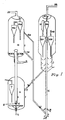
- the FCC regenerator vessel 1 of fig.1 receives spent catalyst from stripper 3.
- Combustion air 5 in the regenerator 1 is distributed at the bottom and catalyst dense phase 6 is maintained typically in partial combustion conditions at which the coke on the catalyst is partially burnt off using controlled amount air at moderate temperature.
- the flue gas of regenerator 1 is separated from the entrained catalyst by cyclone 7 or a series of cyclones.
- the partially regenerated catalyst is lifted from regenerator 1 to regenerator 2 at the top via lift line 9 by using lift air 8 and plug valve at 1 ⁇ .
- Secondary air 11 is distributed at the bottom of regenerator 2 such that the dense bed 12 is maintained and the catalyst is almost completely burnt off the coke below ⁇ .1 wt%.
- the regenerated catalyst is withdrawn from line 13A having pressure equalizer 13B and fed to the bottom of the riser 4 with lift steam from inlet 14 and hydrocarbon feed injection 15 and the mixture of hydrocarbon and catalyst flow through the riser 16 followed by counter-current steam stripping in the stripper 3.
- the stripped and spent catalyst flows beck to regenerator 1 through pipe 17 for continuous regeneration and circulation.
- the product hydrocarbon at the riser end is separated from the catalyst using cyclone 18A, 18B, second stage reactor cyclone 21A, reactor plenum 22A and directed to product fractionator via transfer line 24.
- the flue gas of regenerator 2 is separated from the entrained catalyst by cyclone/series of cyclone 19A,19B and discharged through outlet 2 ⁇ .
- Fig.2 illustrates the FCC apparatus of present invention where a separator 44 using steam is employed to transport the relatively lighter and finer catalyst particles to a regenerator vessel 46 after separating from the above said steam using cyclone(s) and relatively heavier end coarser catalyst particles from the dense bed from which the adsorbent is either directly recycled back to the riser bottom or could be partially or completely burnt off the coke in a coke burner before recycling to the riser bottom.
- a separator 44 using steam is employed to transport the relatively lighter and finer catalyst particles to a regenerator vessel 46 after separating from the above said steam using cyclone(s) and relatively heavier end coarser catalyst particles from the dense bed from which the adsorbent is either directly recycled back to the riser bottom or could be partially or completely burnt off the coke in a coke burner before recycling to the riser bottom.
- the apparatus of the present invention is illustrated in Fig.2.
- the mixture of spent catalyst and adsorbent particles enter near the middle of a separator 44 via spent catalyst standpipe 2 and a valve 3.
- Steam introduced through pipe 37 is injected at the bottom of separator 44 to help maintain a dense bed 41 of the relatively heavier and coarser adsorbent particles.
- the superficial velocity in separator 44 is maintained sufficiently so that the relatively lighter and finer catalyst particles are transported to the top of a lift line 45 provided at the upper section of separator 43.
- Lift line 45 preferably has a reduced cross section than that of separator 43, and wherein steam is injected at different elevation to facilitate an easy transport of the catalyst particles.
- cyclones 14A ,14B are employed to separate the catalyst from steam, which is recovered through outlet 35 and may be recycled at different sections of stripper 48 and riser reactor 43 such as at 25,26,4 ⁇ or may be mixed with product hydrocarbons discharged from outlet 34.
- a purge outlet 38 is provided with burner 47 so as to withdraw a net stream of adsorbent on continuous basis particularly when the residue feed being processed contains very high CCR.
- the adsorbent in such an instance is preferably calcined coke particles, and a net stream of coke thus withdrawn helps to minimize the net heat generation in the system which allows the apparatus to operate with feed upto very high CCR level.
- the hot regenerated catalyst may be withdrawn from the regenerator via line 42 and mixed with adsorbent at the separator. It may noted that the separator temperature should be maintained within maximum 6 ⁇ °C and preferably below 55 ⁇ °C to achieve the best catalyst thermal and hydro thermal stability.
- the catalyst flows through cyclone diplegs 15A,15B to regenerator 46 where air is injected through in controlled or in excess amount depending on the partial or complete combustion of the coke on the catalyst as felt necessary.
- a dense bed of catalyst particles is formed in regenerator 46 where the flue gas is separated using cyclone 19A,19B and allowed to flow via plenum 2 ⁇ to the flue gas and power recovery section.
- the regenerated catalyst is withdrawn through line 11 with pressure equalizer 22 and recycled back to riser 43 at an intermediate riser elevation via pipe 23.
- the adsorbent particles are withdrawn from separator 44 via downcomer 36 to adsorbent burner 47.
- Oxygen containing gas is injected at the burner bottom via pipe 4 so that partial or total burning of the coke is achieved.
- the flue gas is separated in the burner cyclone 39.
- the burner is cooled by any suitable means for controlling the temperature upto a maximum of 75 ⁇ °C, but such cooling means may not be necessary since a separate coke stream is withdrawn continuously from outlet 38, especially when residue of very high CCR is processed.
- the preferred adsorbent in such operation is calcined coke and therefore it can be removed on a continuous basis from the apparatus which helps in maintaining the heat balance by minimizing the net heat generation in the overall process.
- the adsorbent after coke burning is recyled from the bottom of burner 47 via standpipe 6 and slide valve 7 to the bottom of the riser.
- Lift steam 25 is injected at the bottom of the riser.
- Residue or poor quality feed is injected at primary feed nozzle 26 so that the CCR, metals and other poisons existing in the residue feed are deposited on the adsorbent particles.
- the velocity is maintained in the riser sufficiently above the transport velocity of the adsorbent and catalyst to lift the adsorbent-catalyst mixture upwardly of riser 43 and eventually at catalyst inlet 23 of riser 43, the hydrocarbon which has been already vaporized and cleaned by the adsorbent, come in contact with the regenerated catalyst to accomplish the actual catalytic cracking reactions and in the process make sufficient vapor to further lift the catalyst, adsorbent and hydrocarbon mixture to the top of riser 43.
- An optional feed nozzle 43 may be employed to inject relatively better quality feedstock or to control the riser temperature profile by allowing to inject quench stream e.g. heavy naphtha, heavy cycle oil etc.
- the hydrocarbon product is separated from the catalyst and adsorbent mixture at the top of the riser by employing known riser terminator devices and preferentially short contact high efficiency terminator 28A,28B.
- the product hydrocarbon vapor discharged through outlet 34 is withdrawn from the top of the reactor after passing through line 3 ⁇ , cyclone 31 and plenum 33 and the spent catalyst is stripped in stripper 35 using stripping steam 4 ⁇ and spent catalyst/adsorbent mixture is withdrawn via standpipe 2 and slide valve 3 to separator 43 to make the solid circulation continuous.
- the distance between the inlet of pipe 6 and pipe 23 in riser tuber 43 should be 2 ⁇ to 4 ⁇ % of the total riser length.
- Adsorbent particles are intended to adsorb the CCR, the poisonous metals e.g. vanadium, nickel etc. basic nitrogen and sulfur rich compounds existing in enriched from in the residual hydrocarbon fractions.
- adsorbent particles are having particle size in the range of 2 ⁇ -5 ⁇ microns but preferably within 3 ⁇ -4 ⁇ microns.
- the particles density may be kept between 15 ⁇ -3 ⁇ kg/m 3 and preferably 18 ⁇ -26 ⁇ kg/m 3 and msot preferably 23 ⁇ -25 ⁇ kg/m 3 .
- the present invention also applied to adsorbent of particle size higher than 55 ⁇ microns and density above 35 ⁇ kg/m 3 but the larger particle size and density pose flow problem in the standpipe and also in the regenerator.
- the adsorbent particles mainly consist of the microspheres composed of alumina, silica alumina, silica magnesia, kaolin clay or a mixture there off having acidic properties or could be totally non acidic.
- These microspeheres could be prepared using the conventional art of FCC catalyst preparation i.e. by preparing the solution of desired chemical composition, its spray drying and calcination.
- these materials have very less acidic cracking activity characterized by Mat activity of less than 15 and surface area of less than 5 m 2 /gm.
- our invention is not limited to low activity adsorbent alone.
- the adsorbent should be calcined coke produced from calcination of raw coke generated in the delayed coking process of petroleum residues.
- Coal particles or other types of coke are also applicable but calcined coke are preferred due to their excellent attrition resistance and physical properties e.g. higher particle density etc. Since, the present process produces a net coke stream for high CCR residue feedstock, stable coke particle having proper mechanical strength, size, shape and density as mentioned herein above, should be used. It may be noted that if the attrition resistance of the coke is not good, small coke fines will be generated which can not be separated in the condition of the dense bed separator device.
- calcined coke rather than raw coke.
- the other advantage of calcined coke is that it has higher density, lower sulphur content and lower volatile matters via a vis raw coke.
- Typical properties of calcined petroleum coke is given below: Ash content ⁇ .17 wt% Sulfur 1.04 wt% Volatile matters(VM) ⁇ .33 wt% Iron 149 ppm Vanadium 3.8 ppm Reel density 2.14 gm/cc Bulk density ⁇ .73 gm/cc Particle density 1.52 gm/cc Attrition resistance 1.2 (division index)
- the calcined coke was obtained from one delayed coker unit processing long residue of atmospheric column. This calcined coke was grinded mechanically to produce the desired particle size range between 2 ⁇ -35 ⁇ microns. It may be noted that when calcined coke is used as the adsorbent, the major intention is to draw a separate stream of net coke from the separator/burner so that the unit heat balance is properly satisfied. Therefore, for safe reuse/disposal of the net coke drawn from the process of this invention, it is preferred to use calcined coke alone, whenever it is preferred, without adding any other adsorbent components as mentioned above .
- vanadium traps such as V-trap additive of M/s. Intercat USA. This could be used alone or in admixture with other adsorbent component as mentioned above except calcined coke.
- concentration of Vanadium trap in the mixture of other adsorbent component may vary from ⁇ -1 ⁇ wt% depending on the concentration of Vanadium in the feed, but usually 1 ⁇ -4 ⁇ wt % is considered sufficient for feed having vanadium upto 5 ⁇ ppm.
- calcined coke In case, the feed contains higher amount of both vanadium and CCR, we prefer to use calcined coke as the adsorbent, since calcined coke has also very good metal trapping ability. It may be noted that raw coke could be used in our application. But the calcined coke is preferred in our process. This is due the fact that our invention involves high velocity separation and riser operation with the adsorbent particles which demand good attrition resistance and relatively higher particle density. Calcined coke has very good attrition resistance which is equivalent to or better than even conventional FCC catalyst and its particle density is also more than raw coke. In general , it may be noted that all these particles should meet the requirements of particle size and/or particle density or both in order to achieve the maximum segregation efficiency in the separator.
- Typical particle size distribution of the adsorbent particles are given below: wt% Adsorbent Particle Size microns ⁇ 3 ⁇ 1 ⁇ 32 ⁇ 3 ⁇ 35 ⁇ 5 ⁇ 365 7 ⁇ 375 9 ⁇ 385 95 39 ⁇ 1 ⁇ 4 ⁇
- the adsorbent particles preferably should be microspherical in nature. However, the present invention is not limited to other shapes of particles.
- the present invention specifically describes the particle size of the catalyst to be within 2 ⁇ -2 ⁇ microns and more preferably 2 ⁇ -17 ⁇ microns and most preferably 2 ⁇ -1 ⁇ microns.
- the particle density may be within 12 ⁇ -18 ⁇ kg/m 3 and more preferably 13 ⁇ -16 ⁇ kg/m 3 and most preferably within 13 ⁇ -14 ⁇ kg/m 3 to obtain best results as disclosed in the present invention.
- catalyst should be preferably micro-spherical in shape.
- the present invention is not restricted to any particular type of FCC catalyst.
- rare earth exchanged Y zeolite, Ultrastable Y zeolite, non crystalline acidic matrix and even other zeolites e. g. shape selective ZSM-5 zeolite may also be used.
- the present invention prefers to have no CO promoters since the both catalyst regenerators and adsorbent burner of the present invention should preferably run in partial combustion mode.
- our invention is not limited CO promoter usage particularly when the feed contains CCR lower than 2 wt%.
- Typical particle size distribution of the catalyst microspheres are; wt% Adsorbent Particle Size microns ⁇ 2 ⁇ 1 ⁇ 4 ⁇ 3 ⁇ 7 ⁇ 5 ⁇ 8 ⁇ 7 ⁇ 95 9 ⁇ 1 ⁇ 5 95 11 ⁇ 1 ⁇ 12 ⁇
- the present invention provides a novel approach to handle residual hydrocarbons having very high CCR, metals and other poisons. Maximum benefit is obtained particularly if the metal level and CCR level of the feed are above 1 ⁇ ppm and 5 wt% on feed respectively.
- metal includes vanadium and nickel. It may be noted that our invention preferentially allow the CCR, metals and other poisons of the feed to deposit on the adsorbent first before contacting with the catalyst. Moreover, a net coke stream is withdrawn from the process which helps to maintain heat balance quite easily for feedstock with igh CCR.
- the spent catalyst and adsorbent mixture enters the separator near middle of the elevation.
- the separator acts as a vessel to segregate the catalyst from the adsorbent particle.
- the separator works on the principle of difference of transport velocities among two types of particles i.e. catalyst and adsorbent. In the prior art, usually settling velocity difference has been employed for such separation. We have discovered now that the best segregation efficiency is achieved by utilizing the transport velocity difference which is further illustrated in Example-1 of the present invention.
- the separator is having an entry line for the spent adsorbent-catalyst mixture and operating within a temperature range of 45 ⁇ -6 ⁇ °C and preferably within 49 ⁇ -55 ⁇ °C, a specified superficial velocity range which is at least 2 ⁇ % above the transport velocity of the largest and heaviest catalyst particle but at least 3 ⁇ % lower than the transport velocity of the lightest and finest adsorbent particle, where in steam is injected at the bottom of the separator to maintain a dense fluidized bed of adsorbent and transporting the spent catalyst particles through a lift line having reduced diameter than that of the separator with additional steam injection points and withdrawing the adsorbent to the burner kept at lower elevation than the separator.
- the lifted catalyst from the separator is separated from the steam and ensuing hydrocarbons in a cyclone or a series of cyclones.
- the catalyst particles fall through the cyclone dipleg to the dense bed of the regenerator.
- superficial velocity is maintained typically within ⁇ .5-1. ⁇ m/s and more preferably within ⁇ .6- ⁇ .8 m/s to have a conventional dense bed regeneration of the catalyst.
- our invention is also applicable to fast fluidized combustor or even two stage regenerator designs.
- the excess air is maintained such that preferably partial combustion is achieved and the coke on regenerated catalyst is preferably less than ⁇ .3 wt%.
- the regenerator temperature is kept with in the limit of 75 ⁇ °C. Since the feed CCR and metals are preferentially deposited on the adsorbent particles, we do not expect too much coke lay down on the catalyst. Therefore, it may not be difficult to keep the regenerator temperature within limit. It may be specifically mentioned that our invention does not require any catalyst cooling even while processing of high CCR feedstock. This is due to the selective deposition of CCR in the adsorbent high efficiency and low severity segregation of catalyst from adsorbent separate withdrawal of coke stream from the adsorbent separator and or burner for maintaining heat balance without requiring catalyst cooling.
- the burner usually runs on the partial combustion mode under controlled air flow in dense bed fluidzation regime.
- the coke burnt from the adsorbent is sufficient to maintain the burner temperature within 7 ⁇ °C and most preferably within 68 ⁇ °C.
- the excess oxygen in the flue gas could be in the range ⁇ -2 vol% and CO/CO 2 may vary in the range ⁇ .2-1 ⁇ vol/vol.
- the vanadium and CCR trapping ability of the adsorbent improves.
- the coke content on the adsorbent is kept in the range of ⁇ .3-2 wt%.
- the adsorbent particles coming from burner or separator are first contacted with preheated heavy residual hydrocarbon in presence of lift steam.
- lift and feed atomization steam (about 1 ⁇ -5 ⁇ wt% of feed may be added in the bottom section of the riser depending on the quality of residue particularly CCR content.
- the adsorbent/oil ratio and the steam/or ratio are varied in the following range: Feed CCR wt% Typical Adsorbent/Residual oil Steam/Residual oil 3 3 ⁇ .3 5 4 ⁇ .5 7 5 ⁇ .7
- the superficial velocity is maintained in the range of 6-1 ⁇ m/s typically which will be sufficient to lift the adsorbent particles through the riser.
- the regenerated catalyst is injected at the intermediate elevation of the riser.
- the catalyst/total hydrocarbon is kept normally in the range of 4-6 wt/wt to achieve best possible results.
- Such feed should have CCR, metals and other poisons as less as possible but definitely lower than those of the residual stream injected at the riser bottom.
- Typical example of such cleaner streams are fresh vacuum gas oil, heavy cycle oil recycle etc.
- the riser top temperature and the intermediate temperature just below the catalyst entry point could be used to control catalyst/oil and adsorbent/residue ratios respectively through the corresponding slide valve.
- Total residence time in the riser bottom section could be 1 ⁇ -4 ⁇ % of the total riser residence time.
- the catalyst residence time in the riser may be maintained etween 1-15 seconds and preferably between 3-8 seconds depending on the severity of the operation desired.
- Stripping steam may be injected at the bottom of the stripper and/or at different elevations to achieve better stripping efficiency.
- 2-5 tons per 1 ⁇ tons of solid flow is the normal rate of total steam flow in the stripper.
- One important aspect here is to maintain higher velocity of the stripping gas typically above ⁇ .2 m/s so that the coarse particles are at least above the minimum fluidization velocity.
- steam purge is given to keep the adsorbent and the catalyst mixture flowable.
- Other non conventional stripping e.g. fas fluidized stripping, hot stripping etc. may also be adopted but not essential in the present invention. This is because, the catalyst separator also enhances stripping efficiency by co-current stripping with high velocity lift steam as described earlier.
- Sand is used in the size range of 22 ⁇ -32 ⁇ microns with particle density of 26 ⁇ kg/m 3 .
- Catalyst is in the size range of 4 ⁇ -15 ⁇ microns with particle density of 145 ⁇ kg/m 3 .
- 8 ⁇ gms of 5 ⁇ /5 ⁇ by wt of sand and catalyst mixture is loaded and air is injected at the bottom of the column at different velocities.
- Solid sample is collected near bottom of the column just above the air entry point. The particle size distribution of the collected solid is done to establish amount of segregation that has taken place. For 1 ⁇ % segregation, the collected sample should contain no particle of size below 2 ⁇ micron i.e. the cut off size between sand and catalyst.
- the separator bed velocity should be above the transport velocity of the catalyst but lower than that of the adsorbent.
- the transport and settling velocities are: Settling velocity Transport velocity Catalyst ⁇ .2 1.3 Sand 1.8 3.5
- This example illustrates the benefits of sequential dual solid processing particularly the vanadium deposition preferentially on the adsorbent particles and thereby improving the activity of the FCC catalyst.
- Vanadium is first deposited (by adapting pore volume impregnation route of Mitchell) at ⁇ and 1 ⁇ ppm on the mixture of catalyst A and adsorbent B mixed in the ratio of 1 ⁇ : ⁇ .6.
- the MAT activity was determined using MAT (micro activity test) condition of 51 ⁇ °C reactor temperature, 2.5 grams solid loading, 3 ⁇ seconds feed injection time and varying feed rate to generate date at different conversion level.
- Feed used is the combined feed used in one commercial FCC unit with CCR ⁇ .4 wt%, boiling range 37 ⁇ -55 ⁇ °C, density of ⁇ .91 gm/cc.
- Vanadium is deposited selectively on the adsorbent B at ⁇ ,1 ⁇ ppm using same pore volume impregnation technique.
- the metal laden adsorbent is then mixed with the catalyst A in the same ratio of ⁇ .6:1 ⁇ .
- MAT activity and product selectivity were measured using the same feed with this solid mixture as performed in above.
- Mat activity is defined as the conversion obtained at WHSV of 11 ⁇ hour -1 and conversion is defined as the wt% product boiling below 216°C including coke.
- coke selectivity is defined as the coke yield (wt% of feed) at 38 wt% conversion level.
Landscapes
- Chemical & Material Sciences (AREA)
- Oil, Petroleum & Natural Gas (AREA)
- Engineering & Computer Science (AREA)
- Chemical Kinetics & Catalysis (AREA)
- General Chemical & Material Sciences (AREA)
- Organic Chemistry (AREA)
- Crystallography & Structural Chemistry (AREA)
- Production Of Liquid Hydrocarbon Mixture For Refining Petroleum (AREA)
Priority Applications (2)
| Application Number | Priority Date | Filing Date | Title |
|---|---|---|---|
| EP98310512A EP1013743B1 (de) | 1998-12-21 | 1998-12-21 | Fluidkatalytisch Krachverfahren |
| US09/219,459 US6149875A (en) | 1998-12-21 | 1998-12-23 | Fluidized catalytic cracking process and apparatus |
Applications Claiming Priority (2)
| Application Number | Priority Date | Filing Date | Title |
|---|---|---|---|
| EP98310512A EP1013743B1 (de) | 1998-12-21 | 1998-12-21 | Fluidkatalytisch Krachverfahren |
| US09/219,459 US6149875A (en) | 1998-12-21 | 1998-12-23 | Fluidized catalytic cracking process and apparatus |
Publications (2)
| Publication Number | Publication Date |
|---|---|
| EP1013743A1 true EP1013743A1 (de) | 2000-06-28 |
| EP1013743B1 EP1013743B1 (de) | 2005-02-02 |
Family
ID=26151536
Family Applications (1)
| Application Number | Title | Priority Date | Filing Date |
|---|---|---|---|
| EP98310512A Expired - Lifetime EP1013743B1 (de) | 1998-12-21 | 1998-12-21 | Fluidkatalytisch Krachverfahren |
Country Status (2)
| Country | Link |
|---|---|
| US (1) | US6149875A (de) |
| EP (1) | EP1013743B1 (de) |
Cited By (6)
| Publication number | Priority date | Publication date | Assignee | Title |
|---|---|---|---|---|
| GB2388559A (en) * | 2002-05-03 | 2003-11-19 | Indian Oil Corp Ltd | Fluidized bed catalytic cracking apparatus |
| WO2006071771A1 (en) * | 2004-12-23 | 2006-07-06 | Abb Lummus Global Inc. | Processing of different feeds in a fluid catalytis cracking unit |
| EP2003186A1 (de) * | 2007-06-12 | 2008-12-17 | General Electric Company | Verfahren und Vorrichtung zur Wiederherstellung von zur Reinigung von Brennstoff verwendeten Adsoprtionsmitteln |
| US7758817B2 (en) | 2006-08-09 | 2010-07-20 | Uop Llc | Device for contacting high contaminated feedstocks with catalyst in an FCC unit |
| WO2011121612A1 (en) * | 2010-03-31 | 2011-10-06 | Indian Oil Corporation Limited | Method and apparatus for catalytic cracking |
| EP3243567B1 (de) * | 2015-01-06 | 2024-01-24 | Qunzhu Li | Kreislaufverfahren für kalten regenerierten katalysator und vorrichtung dafür |
Families Citing this family (14)
| Publication number | Priority date | Publication date | Assignee | Title |
|---|---|---|---|---|
| US7381322B2 (en) * | 2002-05-08 | 2008-06-03 | Indian Oil Corporation Limited | Resid cracking apparatus with catalyst and adsorbent regenerators and a process thereof |
| US20040262197A1 (en) * | 2003-06-24 | 2004-12-30 | Mcgregor Duane R. | Reduction of NOx in low CO partial-burn operation using full burn regenerator additives |
| US7622625B2 (en) * | 2004-11-01 | 2009-11-24 | Uop Llc | Purge gas streams to stagnant zones within oxygenate-to-olefin reactor |
| CN101164687B (zh) * | 2006-10-20 | 2010-05-12 | 中国石油化工股份有限公司 | 多反应区组合式反应器 |
| CN101164686B (zh) * | 2006-10-20 | 2010-05-12 | 中国石油化工股份有限公司 | 多床层组合式反应器 |
| US9771526B2 (en) | 2010-07-08 | 2017-09-26 | Indian Oil Corporation Ltd. | Multi riser resid catalytic cracking process and apparatus |
| US8609566B2 (en) | 2011-02-28 | 2013-12-17 | Uop Llc | Process for venting a catalyst cooler |
| US8936756B2 (en) | 2011-02-28 | 2015-01-20 | Uop Llc | Apparatus for venting a catalyst cooler |
| US9073005B2 (en) * | 2011-06-09 | 2015-07-07 | Sri International | Falling microbead counter-flow process for separating gas mixtures |
| US20140235429A1 (en) | 2011-10-12 | 2014-08-21 | Indian Oil Corporation Ltd. | Process for enhancing nickel tolerance of heavy hydrocarbon cracking catalysts |
| AU2017325716B2 (en) | 2016-09-16 | 2020-01-30 | Lummus Technology Llc | Fluid catalytic cracking process and apparatus for maximizing light olefin yield and other applications |
| US11286431B2 (en) | 2019-07-02 | 2022-03-29 | Lummus Technology Llc | Fluid catalytic cracking processes and apparatus |
| ES3013621T3 (en) | 2019-07-15 | 2025-04-14 | Lummus Technology Inc | Fluid catalytic cracking process and apparatus for maximizing light olefin yield and other applications |
| CN116712947B (zh) * | 2023-08-02 | 2024-02-06 | 罗托布斯特(上海)氢能科技有限公司 | 近海设施及船用可流动式原料气体催化热裂解系统及工艺 |
Citations (1)
| Publication number | Priority date | Publication date | Assignee | Title |
|---|---|---|---|---|
| EP0272973A1 (de) * | 1986-12-17 | 1988-06-29 | Institut Français du Pétrole | Verfahren und Vorrichtung zum katalytischen Kracken von Kohlenwasserstoffeinsätzen in einer Umwandlungszone, worin inerte und katalytische Teilchen zirkulieren |
Family Cites Families (12)
| Publication number | Priority date | Publication date | Assignee | Title |
|---|---|---|---|---|
| US4064038A (en) * | 1973-05-21 | 1977-12-20 | Universal Oil Products Company | Fluid catalytic cracking process for conversion of residual oils |
| US4892643A (en) * | 1986-09-03 | 1990-01-09 | Mobil Oil Corporation | Upgrading naphtha in a single riser fluidized catalytic cracking operation employing a catalyst mixture |
| US4787967A (en) * | 1986-09-03 | 1988-11-29 | Mobil Oil Corporation | Process for two-phase fluid catalytic cracking system |
| US4814068A (en) * | 1986-09-03 | 1989-03-21 | Mobil Oil Corporation | Fluid catalytic cracking process and apparatus for more effective regeneration of zeolite catalyst |
| US4971766A (en) * | 1988-06-10 | 1990-11-20 | Mobil Oil Corporation | Apparatus for FCC process with catalyst separation |
| US4895636A (en) * | 1988-06-10 | 1990-01-23 | Mobil Oil Corporation | FCC process with catalyst separation |
| US4904281A (en) * | 1988-07-15 | 1990-02-27 | Engelhard Corporation | Method and apparatus for separation of solids from a gaseous stream |
| US4875997A (en) * | 1988-11-17 | 1989-10-24 | Montana Refining Company | Process for treating hydrocarbons containing mercaptans |
| US4927522A (en) * | 1988-12-30 | 1990-05-22 | Mobil Oil Corporation | Multiple feed point catalytic cracking process using elutriable catalyst mixture |
| US5196172A (en) * | 1989-05-16 | 1993-03-23 | Engelhard Corporation | Apparatus for the fluid catalytic cracking of hydrocarbon feed employing a separable mixture of catalyst and sorbent particles |
| US5059302A (en) * | 1989-05-16 | 1991-10-22 | Engelhard Corporation | Method and apparatus for the fluid catalytic cracking of hydrocarbon feed employing a separable mixture of catalyst and sorbent particles |
| US5110775A (en) * | 1990-12-28 | 1992-05-05 | Mobil Oil Corporation | Two stage combustion process for cracking catalyst regeneration |
-
1998
- 1998-12-21 EP EP98310512A patent/EP1013743B1/de not_active Expired - Lifetime
- 1998-12-23 US US09/219,459 patent/US6149875A/en not_active Expired - Lifetime
Patent Citations (1)
| Publication number | Priority date | Publication date | Assignee | Title |
|---|---|---|---|---|
| EP0272973A1 (de) * | 1986-12-17 | 1988-06-29 | Institut Français du Pétrole | Verfahren und Vorrichtung zum katalytischen Kracken von Kohlenwasserstoffeinsätzen in einer Umwandlungszone, worin inerte und katalytische Teilchen zirkulieren |
Cited By (13)
| Publication number | Priority date | Publication date | Assignee | Title |
|---|---|---|---|---|
| DE10219863B4 (de) * | 2002-05-03 | 2014-03-27 | Indian Oil Corporation Limited | Rückstandscrackvorrichtung mit Katalysator- und Adsorptionsmittelregeneratoren und Verfahren hierfür |
| FR2839900A1 (fr) * | 2002-05-03 | 2003-11-28 | Indian Oil Corp Ltd | Appareil et procede de craquage catalytique a lit fluidise |
| GB2388559B (en) * | 2002-05-03 | 2005-07-06 | Indian Oil Corp Ltd | Resid cracking apparatus with catalyst and adsorbent regenerators and a process thereof |
| GB2388559A (en) * | 2002-05-03 | 2003-11-19 | Indian Oil Corp Ltd | Fluidized bed catalytic cracking apparatus |
| WO2006071771A1 (en) * | 2004-12-23 | 2006-07-06 | Abb Lummus Global Inc. | Processing of different feeds in a fluid catalytis cracking unit |
| US7682501B2 (en) | 2004-12-23 | 2010-03-23 | Abb Lummus Global, Inc. | Processing of different feeds in a fluid catalytic cracking unit |
| JP2008525597A (ja) * | 2004-12-23 | 2008-07-17 | エービービー ルマス グローバル インコーポレイテッド | 流動接触分解ユニットにおける異質流体の処理 |
| US8986617B2 (en) | 2004-12-23 | 2015-03-24 | Lummus Technology Inc. | Processing of different feeds in a fluid catalytic cracking unit |
| US7758817B2 (en) | 2006-08-09 | 2010-07-20 | Uop Llc | Device for contacting high contaminated feedstocks with catalyst in an FCC unit |
| EP2003186A1 (de) * | 2007-06-12 | 2008-12-17 | General Electric Company | Verfahren und Vorrichtung zur Wiederherstellung von zur Reinigung von Brennstoff verwendeten Adsoprtionsmitteln |
| WO2011121612A1 (en) * | 2010-03-31 | 2011-10-06 | Indian Oil Corporation Limited | Method and apparatus for catalytic cracking |
| US8840846B2 (en) | 2010-03-31 | 2014-09-23 | Indian Oil Corporation Ltd. | Method and apparatus for catalytic cracking |
| EP3243567B1 (de) * | 2015-01-06 | 2024-01-24 | Qunzhu Li | Kreislaufverfahren für kalten regenerierten katalysator und vorrichtung dafür |
Also Published As
| Publication number | Publication date |
|---|---|
| US6149875A (en) | 2000-11-21 |
| EP1013743B1 (de) | 2005-02-02 |
Similar Documents
| Publication | Publication Date | Title |
|---|---|---|
| EP1013743B1 (de) | Fluidkatalytisch Krachverfahren | |
| US3821103A (en) | Conversion of sulfur contaminated hydrocarbons | |
| US4875994A (en) | Process and apparatus for catalytic cracking of residual oils | |
| EP0106052B1 (de) | Entmetallisierung und Entkarbonisierung schwerer Rückstandsöl-Einsatzprodukte | |
| US4478708A (en) | Method and apparatus for separating fluidized solid particles suspended in gasiform material | |
| US4331533A (en) | Method and apparatus for cracking residual oils | |
| US8226818B2 (en) | FCC process with spent catalyst recycle | |
| US6063263A (en) | Process for feed contacting with immediate catalyst separation | |
| US9771526B2 (en) | Multi riser resid catalytic cracking process and apparatus | |
| US6656344B1 (en) | Fluidized catalytic cracking process | |
| US6110356A (en) | Slurry circulation process and system for fluidized particle contacting | |
| EP0171460A1 (de) | Verfahren zur katalytischen Spaltung von Residualölen mit Trockengas als Auftriebgas in einem Steigrohrreaktor | |
| US7008595B2 (en) | Resid cracking apparatus with catalyst and adsorbent regenerators and a process thereof | |
| US7381322B2 (en) | Resid cracking apparatus with catalyst and adsorbent regenerators and a process thereof | |
| US10889765B2 (en) | Process and apparatus for enhanced removal of contaminants in fluid catalytic cracking processes | |
| CN114401785B (zh) | 用于使轻烯烃产率最大化的流化催化裂化方法和装置 | |
| US5110775A (en) | Two stage combustion process for cracking catalyst regeneration | |
| JPH0321695A (ja) | 触媒と吸着材の分離できる混合物を使用する炭化水素フイードの流動触媒クラツキングのための方法及び装置 | |
| WO2016018554A1 (en) | Fcc units, separation apparatuses, and methods for separating regenerated catalyst | |
| US4693809A (en) | Hydrocarbon conversion process | |
| EP0236055A2 (de) | Verfahren zur Behandlung von Kohlenwasserstoffen | |
| EP0066387B1 (de) | Kombinationsverfahren für die Verbesserung von Residualölen | |
| EP1146106B1 (de) | Verfahren und Apparat zum Zusammenbringen von Einsatz mit sofortiger Trennung von Katalysator | |
| WO2024149076A1 (zh) | 一种流化催化转化系统及其应用 |
Legal Events
| Date | Code | Title | Description |
|---|---|---|---|
| PUAI | Public reference made under article 153(3) epc to a published international application that has entered the european phase |
Free format text: ORIGINAL CODE: 0009012 |
|
| AK | Designated contracting states |
Kind code of ref document: A1 Designated state(s): FR GB |
|
| AX | Request for extension of the european patent |
Free format text: AL;LT;LV;MK;RO;SI |
|
| 17P | Request for examination filed |
Effective date: 20001227 |
|
| AKX | Designation fees paid |
Free format text: AT BE |
|
| RBV | Designated contracting states (corrected) |
Designated state(s): FR GB |
|
| 17Q | First examination report despatched |
Effective date: 20030210 |
|
| REG | Reference to a national code |
Ref country code: DE Ref legal event code: 8566 |
|
| GRAJ | Information related to disapproval of communication of intention to grant by the applicant or resumption of examination proceedings by the epo deleted |
Free format text: ORIGINAL CODE: EPIDOSDIGR1 |
|
| GRAP | Despatch of communication of intention to grant a patent |
Free format text: ORIGINAL CODE: EPIDOSNIGR1 |
|
| GRAP | Despatch of communication of intention to grant a patent |
Free format text: ORIGINAL CODE: EPIDOSNIGR1 |
|
| RIN1 | Information on inventor provided before grant (corrected) |
Inventor name: MANDAL, SUKUMAR Inventor name: MAKHIJA, SATISH Inventor name: BHATTACHARYYA, DEBASIS Inventor name: GHOSH, SOBHAN Inventor name: DAS, ASIT KUMAR Inventor name: SINGH, SANJEEV Inventor name: MURTHY, VUTUKURU LAKSHIMINARASHIMHA Inventor name: RAO, MARRI RAMA |
|
| GRAS | Grant fee paid |
Free format text: ORIGINAL CODE: EPIDOSNIGR3 |
|
| GRAA | (expected) grant |
Free format text: ORIGINAL CODE: 0009210 |
|
| RIN1 | Information on inventor provided before grant (corrected) |
Inventor name: MANDAL, SUKUMAR Inventor name: MAKHIJA, SATISH Inventor name: BHATTACHARYYA, DEBASIS Inventor name: GHOSH, SOBHAN Inventor name: DAS, ASIT KUMAR Inventor name: SINGH, SANJEEV Inventor name: MURTHY, VUTUKURU LAKSHIMINARASHIMHA Inventor name: RAO, MARRI RAMA |
|
| AK | Designated contracting states |
Kind code of ref document: B1 Designated state(s): FR GB |
|
| REG | Reference to a national code |
Ref country code: GB Ref legal event code: FG4D |
|
| PLBE | No opposition filed within time limit |
Free format text: ORIGINAL CODE: 0009261 |
|
| STAA | Information on the status of an ep patent application or granted ep patent |
Free format text: STATUS: NO OPPOSITION FILED WITHIN TIME LIMIT |
|
| 26N | No opposition filed |
Effective date: 20051103 |
|
| ET | Fr: translation filed | ||
| REG | Reference to a national code |
Ref country code: FR Ref legal event code: ST Effective date: 20110831 |
|
| PG25 | Lapsed in a contracting state [announced via postgrant information from national office to epo] |
Ref country code: FR Free format text: LAPSE BECAUSE OF NON-PAYMENT OF DUE FEES Effective date: 20110103 |
|
| REG | Reference to a national code |
Ref country code: FR Ref legal event code: D3 Effective date: 20120214 |
|
| PGRI | Patent reinstated in contracting state [announced from national office to epo] |
Ref country code: FR Effective date: 20120215 |
|
| REG | Reference to a national code |
Ref country code: FR Ref legal event code: PLFP Year of fee payment: 18 |
|
| REG | Reference to a national code |
Ref country code: FR Ref legal event code: PLFP Year of fee payment: 19 |
|
| REG | Reference to a national code |
Ref country code: FR Ref legal event code: PLFP Year of fee payment: 20 |
|
| PGFP | Annual fee paid to national office [announced via postgrant information from national office to epo] |
Ref country code: FR Payment date: 20171104 Year of fee payment: 20 |
|
| PGFP | Annual fee paid to national office [announced via postgrant information from national office to epo] |
Ref country code: GB Payment date: 20171104 Year of fee payment: 20 |
|
| REG | Reference to a national code |
Ref country code: GB Ref legal event code: PE20 Expiry date: 20181220 |
|
| PG25 | Lapsed in a contracting state [announced via postgrant information from national office to epo] |
Ref country code: GB Free format text: LAPSE BECAUSE OF EXPIRATION OF PROTECTION Effective date: 20181220 |