EP1013829A2 - Fräsgerät - Google Patents
Fräsgerät Download PDFInfo
- Publication number
- EP1013829A2 EP1013829A2 EP99204507A EP99204507A EP1013829A2 EP 1013829 A2 EP1013829 A2 EP 1013829A2 EP 99204507 A EP99204507 A EP 99204507A EP 99204507 A EP99204507 A EP 99204507A EP 1013829 A2 EP1013829 A2 EP 1013829A2
- Authority
- EP
- European Patent Office
- Prior art keywords
- milling
- hammer
- roll
- strike
- axis
- Prior art date
- Legal status (The legal status is an assumption and is not a legal conclusion. Google has not performed a legal analysis and makes no representation as to the accuracy of the status listed.)
- Granted
Links
- 238000003801 milling Methods 0.000 title claims abstract description 91
- 239000010426 asphalt Substances 0.000 claims abstract description 4
- 239000004567 concrete Substances 0.000 claims abstract description 4
- 239000000463 material Substances 0.000 claims description 4
- 230000008878 coupling Effects 0.000 claims description 2
- 238000010168 coupling process Methods 0.000 claims description 2
- 238000005859 coupling reaction Methods 0.000 claims description 2
- 239000011435 rock Substances 0.000 claims description 2
- 230000002349 favourable effect Effects 0.000 description 9
- 230000005540 biological transmission Effects 0.000 description 7
- 229910052751 metal Inorganic materials 0.000 description 2
- 239000002184 metal Substances 0.000 description 2
- 238000000034 method Methods 0.000 description 2
- 230000008569 process Effects 0.000 description 2
- UONOETXJSWQNOL-UHFFFAOYSA-N tungsten carbide Chemical compound [W+]#[C-] UONOETXJSWQNOL-UHFFFAOYSA-N 0.000 description 2
- 230000009471 action Effects 0.000 description 1
- 238000013459 approach Methods 0.000 description 1
- 230000008901 benefit Effects 0.000 description 1
- 230000001419 dependent effect Effects 0.000 description 1
- 230000000694 effects Effects 0.000 description 1
- 230000002093 peripheral effect Effects 0.000 description 1
- 238000007790 scraping Methods 0.000 description 1
- 239000004575 stone Substances 0.000 description 1
Images


Classifications
-
- B—PERFORMING OPERATIONS; TRANSPORTING
- B28—WORKING CEMENT, CLAY, OR STONE
- B28D—WORKING STONE OR STONE-LIKE MATERIALS
- B28D1/00—Working stone or stone-like materials, e.g. brick, concrete or glass, not provided for elsewhere; Machines, devices, tools therefor
- B28D1/18—Working stone or stone-like materials, e.g. brick, concrete or glass, not provided for elsewhere; Machines, devices, tools therefor by milling, e.g. channelling by means of milling tools
- B28D1/186—Tools therefor, e.g. having exchangeable cutter bits
-
- E—FIXED CONSTRUCTIONS
- E01—CONSTRUCTION OF ROADS, RAILWAYS, OR BRIDGES
- E01C—CONSTRUCTION OF, OR SURFACES FOR, ROADS, SPORTS GROUNDS, OR THE LIKE; MACHINES OR AUXILIARY TOOLS FOR CONSTRUCTION OR REPAIR
- E01C23/00—Auxiliary devices or arrangements for constructing, repairing, reconditioning, or taking-up road or like surfaces
- E01C23/06—Devices or arrangements for working the finished surface; Devices for repairing or reconditioning the surface of damaged paving; Recycling in place or on the road
- E01C23/08—Devices or arrangements for working the finished surface; Devices for repairing or reconditioning the surface of damaged paving; Recycling in place or on the road for roughening or patterning; for removing the surface down to a predetermined depth high spots or material bonded to the surface, e.g. markings; for maintaining earth roads, clay courts or like surfaces by means of surface working tools, e.g. scarifiers, levelling blades
- E01C23/085—Devices or arrangements for working the finished surface; Devices for repairing or reconditioning the surface of damaged paving; Recycling in place or on the road for roughening or patterning; for removing the surface down to a predetermined depth high spots or material bonded to the surface, e.g. markings; for maintaining earth roads, clay courts or like surfaces by means of surface working tools, e.g. scarifiers, levelling blades using power-driven tools, e.g. vibratory tools
Definitions
- the invention relates to a milling apparatus, for the milling of hard materials like concrete, rock or asphalt, provided with a milling roll mounted for rotation around a central longitudinal axis, to a surface of which milling roll a number of milling bits are connected, and a hammer axis, mounted for rotation around the central longitudinal axis, for operationally applying additional impulse moments to the milling bits.
- a milling apparatus of this kind is known from WO 89/01837.
- the known milling apparatus is used, like the inventive milling apparatus, for example for equalizing a road surface, in which process a partly worn off wearing course is removed.
- the milling roll is mounted in a wheeled frame with an adjustable height and the frame is provided with a power source for driving the milling roll and for propelling the apparatus.
- the milling bits mounted on an outer surface of the milling roll are usually welded-on tool holders, in which the actual bits made for example of tungsten carbide are mounted.
- the present invention is based on the observation that an moment should be preferably directed in the direction of movement of the milling bits.
- a favourable embodiment according to an aspect of the invention is therefore characterized in that the hammer axis is arranged for applying the additional impulse moments in at least substantially a tangential direction to the milling bits.
- a favourable embodiment according to another aspect of the invention in which a relatively slow rotating hammer axis may generate an additional impulse moment at a relatively high repetition frequency, is characterized in that an inner wall of the milling roll is provided with strike shoulders and that the hammer axis is provided with hammers, mounted for operationally engaging the strike shoulders.
- the apparatus is according to another aspect of the invention characterized in that every hammer is pivotally mounted to an arm connected to the hammer axis, such that the hammer can strike a strike shoulder if the hammer is at least substantially in line with the arm.
- the invention moreover aims at reducing the wear and tear of the bearings of the hammer axis and to increase the control convenience of the milling apparatus by reducing tangential directed vibrations.
- a favourable embodiment according to another aspect of the invention, which realizes these improvements, is characterized in that the hammers are distributed around the hammer axis to obtain a well-balanced arrangement.
- a favourable embodiment according to another aspect of the invention which has as an advantage that even with a milling roll with a limited stiffness a good distribution of the additional impulse moments over the milling bits is obtained is characterized in that the hammers are distributed at least substantially regularly spaced along the hammer axis.
- a very favourable embodiment according to another aspect of the invention is characterized in that a hammer is mounted such that it can strike a plurality of strike shoulders.
- the strike shoulders run at least substantially regularly spaced along at least substantially the entire length of the inner wall of the milling roll.
- a further favourable embodiment according to an aspect of the invention is characterized in that the milling roll and the hammer axis each are provided with individual drive means.
- This embodiment is more expensive than an embodiment in which only the hammer axis is driven but is provides an opportunity to select for a particular material to be milled the rotational speed of the milling roll and the rotational speed of the hammer axis in combination in order to optimize a particular parameter, like the speed of the milling process or the smoothness of the milled surface.
- a further very favourable embodiment according to an aspect of the invention is characterized in that in an operational mode the hammer axis rotates four to eight times as fast as the milling roll. It is possible then to generate an additional impulse moment with a very high frequency, which greatly enhances the effectiveness of the milling process.
- a favourable embodiment according to another aspect of the invention is characterized in that coupling means are provided between the drive means and the milling roll, in which at least in a tangential direction some clearance exists.
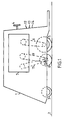
- Fig. 1 represents a possible embodiment of a milling apparatus 1, arranged for removing a layer of a road surface 2, consisting of concrete, asphalt or a stone product.
- Milling apparatus 1 comprises a front wheel 3, enabling the apparatus to be steered with the aid of a steering wheel 4 and two back wheels 5, connected via a transmission 6 to a diesel motor 7 for driving the milling apparatus 1.
- milling apparatus 1 is provided with a milling roll 8, covered with milling bits and connected via a transmission 9 to diesel engine 7.
- milling roll 8 comprises a hammer axis 10, provided with hammers, which hammer axis 10 is connected via a transmission 11 to diesel engine 7.
- Transmissions 6, 9 and 11 comprise multiple v-belts for connecting them to a main axis of diesel motor 7 via variable transmission units, well known in the art, such that the speed of milling apparatus 1, the peripheral velocity of milling roll 8 and the linear speed of hammer axis 10 can be adjusted mutually independent with control devices 12,13,14, dependent upon the operational circumstances, like the desired milling depth, the smoothness of the milled surface and the hardness of the road surface 2. It is also possible to drive a hydraulic pump unit with diesel engine 7 and to provide back wheels 5, milling roll 8 and hammer axis 10 each with a hydraulic motor, in which case the linear speeds can be adjusted independently in a manner well known in the art.
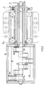
- Fig. 2 represents a longitudinal cross section of a possible embodiment of a milling roll according to the invention, in which a first pulley 15, driven by transmission 9, drives an inner roll 16.
- Inner roll 16 and pulley 15 are connected by a hollow axis 17, which hollow axis 17 is supported by two ball bearings 18,19 mounted in a housing 20, which housing 20 in turn is rigidly mounted to the frame of milling apparatus 1.
- an outer roll on which the milling bits are placed, is placed round inner roll 16 and is fixed to it with bolts.
- the outer roll is not shown in this figure.
- a second pulley 21 is provided, driven by transmission 11, for driving a hammer axis 22.
- Hammer axis 22 is supported by four ball bearings 23,24,25,26, mounted in hollow axis 17 and in inner roll 16.
- Hammer axis 22 is provided with six arms 27a,..27f, which are distributed regularly spaced along hammer axis 22 and which are each successively rotated over an angle of 60 degrees.
- six hammers 28a,..,28f are pivotally connected, which can, if they are located in line with the corresponding arms, hit the two strike shoulders 29,30 which are located on an inner wall of inner roll 16, to which they will transfer a tangentially directed impulse.
- the hammer is slowed down, but the linear speeds of the inner roll and the hammer axis are chosen such that the hammer is again in line with the corresponding arm when it approaches the next strike shoulder.
- Fig. 3 represents a transverse cross section of a possible embodiment of a milling roll, with an inner roll 16 on an inner wall of which the two strike shoulders 29,30 are connected and with an outer roll 31, the inner roll 16 and the outer roll 31 together forming the milling roll 8.
- the milling bits used are known in the art and consist of a holder 32, which is welded onto outer roll 31 and a cutter 33 of a cutting metal which is rotatable mounted in holder 32 and which may be provided with a tip 34 made of tungsten carbide. From Fig.
- Fig. 4 represents a possible distribution of the milling bits on a milling roll 31, which milling roll 31 is showed for clarity in a developed position, in the sense that in an operational position the lines AA' and BB' coincide. It may be noticed that in a direction indicated by an arrow, which is also the direction of propagation, the milling bits are located such that always a limited number of cutting metal cutters 33 are active and will receive the additional impulse moments of the hammers 28a,..,28f, while in a direction perpendicular to the direction of propagation the milling bits are located such that the surface to be milled will be evenly milled.
Landscapes
- Engineering & Computer Science (AREA)
- Mining & Mineral Resources (AREA)
- Mechanical Engineering (AREA)
- Architecture (AREA)
- Civil Engineering (AREA)
- Structural Engineering (AREA)
- Road Repair (AREA)
- Holo Graphy (AREA)
- Shovels (AREA)
- Crushing And Grinding (AREA)
- Earth Drilling (AREA)
Applications Claiming Priority (2)
| Application Number | Priority Date | Filing Date | Title |
|---|---|---|---|
| NL1010895 | 1998-12-27 | ||
| NL1010895A NL1010895C1 (nl) | 1998-12-27 | 1998-12-27 | Freesinrichting. |
Publications (3)
| Publication Number | Publication Date |
|---|---|
| EP1013829A2 true EP1013829A2 (de) | 2000-06-28 |
| EP1013829A3 EP1013829A3 (de) | 2001-11-28 |
| EP1013829B1 EP1013829B1 (de) | 2005-02-09 |
Family
ID=19768370
Family Applications (1)
| Application Number | Title | Priority Date | Filing Date |
|---|---|---|---|
| EP99204507A Expired - Lifetime EP1013829B1 (de) | 1998-12-27 | 1999-12-27 | Fräsgerät |
Country Status (4)
| Country | Link |
|---|---|
| EP (1) | EP1013829B1 (de) |
| AT (1) | ATE288969T1 (de) |
| DE (1) | DE69923649T2 (de) |
| NL (1) | NL1010895C1 (de) |
Cited By (3)
| Publication number | Priority date | Publication date | Assignee | Title |
|---|---|---|---|---|
| WO2005005119A1 (de) * | 2003-07-14 | 2005-01-20 | Wirtgen Gmbh | Baumaschine |
| US8181322B2 (en) | 2008-05-26 | 2012-05-22 | Wirtgen Gmbh | Tool for removing a chisel |
| CN112720884A (zh) * | 2020-12-23 | 2021-04-30 | 中交一公局集团有限公司海外分公司 | 刨毛设备 |
Family Cites Families (2)
| Publication number | Priority date | Publication date | Assignee | Title |
|---|---|---|---|---|
| DE19547698C2 (de) * | 1995-12-20 | 2000-08-17 | Wirtgen Gmbh | Vorrichtung und Verfahren zum Abfräsen von harten Oberflächen, insbesondere von Straßenbelägen |
| DE19754371C1 (de) * | 1996-08-27 | 1998-11-26 | Nikolaus Wendel | Fräsmaschine mit rotierendem Fräswerkzeug für gesteinsartige Materialien |
-
1998
- 1998-12-27 NL NL1010895A patent/NL1010895C1/nl not_active IP Right Cessation
-
1999
- 1999-12-27 AT AT99204507T patent/ATE288969T1/de not_active IP Right Cessation
- 1999-12-27 DE DE69923649T patent/DE69923649T2/de not_active Expired - Fee Related
- 1999-12-27 EP EP99204507A patent/EP1013829B1/de not_active Expired - Lifetime
Cited By (9)
| Publication number | Priority date | Publication date | Assignee | Title |
|---|---|---|---|---|
| WO2005005119A1 (de) * | 2003-07-14 | 2005-01-20 | Wirtgen Gmbh | Baumaschine |
| JP2007533875A (ja) * | 2003-07-14 | 2007-11-22 | ヴィルトゲン ゲゼルシャフト ミット ベシュレンクテル ハフツング | 建設機械 |
| US7401862B2 (en) | 2003-07-14 | 2008-07-22 | Wirtgen Gmbh | Construction machine |
| EP2060375A1 (de) * | 2003-07-14 | 2009-05-20 | Wirtgen GmbH | Baumaschine |
| CN1816432B (zh) * | 2003-07-14 | 2010-10-27 | 维特根有限公司 | 建筑机械 |
| US8181322B2 (en) | 2008-05-26 | 2012-05-22 | Wirtgen Gmbh | Tool for removing a chisel |
| US8286316B2 (en) | 2008-05-26 | 2012-10-16 | Wirtgen Gmbh | Tool for removing a chisel |
| US9157320B2 (en) | 2008-05-26 | 2015-10-13 | Wirtgen Gmbh | Tool for removing a chisel |
| CN112720884A (zh) * | 2020-12-23 | 2021-04-30 | 中交一公局集团有限公司海外分公司 | 刨毛设备 |
Also Published As
| Publication number | Publication date |
|---|---|
| EP1013829B1 (de) | 2005-02-09 |
| DE69923649T2 (de) | 2006-03-16 |
| DE69923649D1 (de) | 2005-03-17 |
| EP1013829A3 (de) | 2001-11-28 |
| NL1010895C1 (nl) | 2000-06-30 |
| ATE288969T1 (de) | 2005-02-15 |
Similar Documents
| Publication | Publication Date | Title |
|---|---|---|
| US7896445B2 (en) | Method and apparatus for the milling cutting of materials | |
| US3683522A (en) | Frustoconical rotary cutter for digging trenches | |
| GB2197009A (en) | Drilling boreholes | |
| US6033031A (en) | Milling machine with vibrating mechanism and rotary drum | |
| DK161985B (da) | Apparat og fremgangsmaade til fremdrivning af et skjold ved tunelboring | |
| US4250760A (en) | Drive assembly for pavement planing apparatus | |
| EP0096585A1 (de) | Bodenbearbeitungsmaschine | |
| EP1013829B1 (de) | Fräsgerät | |
| US3269039A (en) | Sonic earth moving machine | |
| US3695722A (en) | Apparatus for treating or digging into surfaces and cutting members for this apparatus | |
| RU2355845C1 (ru) | Виброраскалыватель | |
| US4920600A (en) | Pipe cleaner | |
| EP0894165B1 (de) | Fräsvorrichtung mit ellipsenförmig angeordneten Fräsmeisseln | |
| US7168501B2 (en) | Rotor system for ground milling or mine milling | |
| US5478139A (en) | Mobile digging/cutting system | |
| US6203113B1 (en) | Cutting drum with percussive bits | |
| WO1998036129A9 (en) | Elliptical disc grinder | |
| US8176990B2 (en) | Apparatus for removing obstructions from a worksite | |
| EP0891531A1 (de) | Vorrichtung zum räumen von minen und minenraumverfahren | |
| WO2002055792A9 (en) | Method and apparatus for vibratory kinetic energy generation and application thereof | |
| US4663868A (en) | Scoop wheel having oscillating impact cutters | |
| US20080245047A1 (en) | Shredder head, and mobile silvicultural vehicle including the same | |
| RU209277U1 (ru) | Устройство для разрушения образований из уплотненного снега и льда на поверхности дорог и тротуаров | |
| RU2136811C1 (ru) | Устройство для скалывания льда | |
| US4366991A (en) | Pavement planing device |
Legal Events
| Date | Code | Title | Description |
|---|---|---|---|
| PUAI | Public reference made under article 153(3) epc to a published international application that has entered the european phase |
Free format text: ORIGINAL CODE: 0009012 |
|
| AK | Designated contracting states |
Kind code of ref document: A2 Designated state(s): AT BE CH CY DE DK ES FI FR GB GR IE IT LI LU MC NL PT SE |
|
| AX | Request for extension of the european patent |
Free format text: AL;LT;LV;MK;RO;SI |
|
| PUAL | Search report despatched |
Free format text: ORIGINAL CODE: 0009013 |
|
| AK | Designated contracting states |
Kind code of ref document: A3 Designated state(s): AT BE CH CY DE DK ES FI FR GB GR IE IT LI LU MC NL PT SE |
|
| AX | Request for extension of the european patent |
Free format text: AL;LT;LV;MK;RO;SI |
|
| 17P | Request for examination filed |
Effective date: 20020507 |
|
| AKX | Designation fees paid |
Free format text: AT BE CH CY DE DK ES FI FR GB GR IE IT LI LU MC NL PT SE |
|
| 17Q | First examination report despatched |
Effective date: 20030623 |
|
| GRAP | Despatch of communication of intention to grant a patent |
Free format text: ORIGINAL CODE: EPIDOSNIGR1 |
|
| GRAS | Grant fee paid |
Free format text: ORIGINAL CODE: EPIDOSNIGR3 |
|
| GRAA | (expected) grant |
Free format text: ORIGINAL CODE: 0009210 |
|
| AK | Designated contracting states |
Kind code of ref document: B1 Designated state(s): AT BE CH CY DE DK ES FI FR GB GR IE IT LI LU MC NL PT SE |
|
| PG25 | Lapsed in a contracting state [announced via postgrant information from national office to epo] |
Ref country code: LI Free format text: LAPSE BECAUSE OF FAILURE TO SUBMIT A TRANSLATION OF THE DESCRIPTION OR TO PAY THE FEE WITHIN THE PRESCRIBED TIME-LIMIT Effective date: 20050209 Ref country code: IT Free format text: LAPSE BECAUSE OF FAILURE TO SUBMIT A TRANSLATION OF THE DESCRIPTION OR TO PAY THE FEE WITHIN THE PRESCRIBED TIME-LIMIT;WARNING: LAPSES OF ITALIAN PATENTS WITH EFFECTIVE DATE BEFORE 2007 MAY HAVE OCCURRED AT ANY TIME BEFORE 2007. THE CORRECT EFFECTIVE DATE MAY BE DIFFERENT FROM THE ONE RECORDED. Effective date: 20050209 Ref country code: FR Free format text: LAPSE BECAUSE OF NON-PAYMENT OF DUE FEES Effective date: 20050209 Ref country code: FI Free format text: LAPSE BECAUSE OF FAILURE TO SUBMIT A TRANSLATION OF THE DESCRIPTION OR TO PAY THE FEE WITHIN THE PRESCRIBED TIME-LIMIT Effective date: 20050209 Ref country code: CH Free format text: LAPSE BECAUSE OF FAILURE TO SUBMIT A TRANSLATION OF THE DESCRIPTION OR TO PAY THE FEE WITHIN THE PRESCRIBED TIME-LIMIT Effective date: 20050209 Ref country code: BE Free format text: LAPSE BECAUSE OF FAILURE TO SUBMIT A TRANSLATION OF THE DESCRIPTION OR TO PAY THE FEE WITHIN THE PRESCRIBED TIME-LIMIT Effective date: 20050209 Ref country code: AT Free format text: LAPSE BECAUSE OF FAILURE TO SUBMIT A TRANSLATION OF THE DESCRIPTION OR TO PAY THE FEE WITHIN THE PRESCRIBED TIME-LIMIT Effective date: 20050209 |
|
| REG | Reference to a national code |
Ref country code: GB Ref legal event code: FG4D |
|
| REG | Reference to a national code |
Ref country code: CH Ref legal event code: EP |
|
| REG | Reference to a national code |
Ref country code: IE Ref legal event code: FG4D |
|
| REF | Corresponds to: |
Ref document number: 69923649 Country of ref document: DE Date of ref document: 20050317 Kind code of ref document: P |
|
| PG25 | Lapsed in a contracting state [announced via postgrant information from national office to epo] |
Ref country code: SE Free format text: LAPSE BECAUSE OF FAILURE TO SUBMIT A TRANSLATION OF THE DESCRIPTION OR TO PAY THE FEE WITHIN THE PRESCRIBED TIME-LIMIT Effective date: 20050509 Ref country code: GR Free format text: LAPSE BECAUSE OF FAILURE TO SUBMIT A TRANSLATION OF THE DESCRIPTION OR TO PAY THE FEE WITHIN THE PRESCRIBED TIME-LIMIT Effective date: 20050509 Ref country code: DK Free format text: LAPSE BECAUSE OF FAILURE TO SUBMIT A TRANSLATION OF THE DESCRIPTION OR TO PAY THE FEE WITHIN THE PRESCRIBED TIME-LIMIT Effective date: 20050509 |
|
| PG25 | Lapsed in a contracting state [announced via postgrant information from national office to epo] |
Ref country code: ES Free format text: LAPSE BECAUSE OF FAILURE TO SUBMIT A TRANSLATION OF THE DESCRIPTION OR TO PAY THE FEE WITHIN THE PRESCRIBED TIME-LIMIT Effective date: 20050520 |
|
| REG | Reference to a national code |
Ref country code: CH Ref legal event code: PL |
|
| PGFP | Annual fee paid to national office [announced via postgrant information from national office to epo] |
Ref country code: NL Payment date: 20051104 Year of fee payment: 7 |
|
| PLBE | No opposition filed within time limit |
Free format text: ORIGINAL CODE: 0009261 |
|
| STAA | Information on the status of an ep patent application or granted ep patent |
Free format text: STATUS: NO OPPOSITION FILED WITHIN TIME LIMIT |
|
| PG25 | Lapsed in a contracting state [announced via postgrant information from national office to epo] |
Ref country code: GB Free format text: LAPSE BECAUSE OF NON-PAYMENT OF DUE FEES Effective date: 20051227 Ref country code: CY Free format text: LAPSE BECAUSE OF FAILURE TO SUBMIT A TRANSLATION OF THE DESCRIPTION OR TO PAY THE FEE WITHIN THE PRESCRIBED TIME-LIMIT Effective date: 20051227 |
|
| PG25 | Lapsed in a contracting state [announced via postgrant information from national office to epo] |
Ref country code: IE Free format text: LAPSE BECAUSE OF NON-PAYMENT OF DUE FEES Effective date: 20051229 |
|
| PG25 | Lapsed in a contracting state [announced via postgrant information from national office to epo] |
Ref country code: MC Free format text: LAPSE BECAUSE OF NON-PAYMENT OF DUE FEES Effective date: 20051231 Ref country code: LU Free format text: LAPSE BECAUSE OF NON-PAYMENT OF DUE FEES Effective date: 20051231 |
|
| PGFP | Annual fee paid to national office [announced via postgrant information from national office to epo] |
Ref country code: DE Payment date: 20051231 Year of fee payment: 7 |
|
| 26N | No opposition filed |
Effective date: 20051110 |
|
| EN | Fr: translation not filed | ||
| GBPC | Gb: european patent ceased through non-payment of renewal fee |
Effective date: 20051227 |
|
| REG | Reference to a national code |
Ref country code: IE Ref legal event code: MM4A |
|
| PG25 | Lapsed in a contracting state [announced via postgrant information from national office to epo] |
Ref country code: NL Free format text: LAPSE BECAUSE OF NON-PAYMENT OF DUE FEES Effective date: 20070701 |
|
| PG25 | Lapsed in a contracting state [announced via postgrant information from national office to epo] |
Ref country code: DE Free format text: LAPSE BECAUSE OF NON-PAYMENT OF DUE FEES Effective date: 20070703 |
|
| NLV4 | Nl: lapsed or anulled due to non-payment of the annual fee |
Effective date: 20070701 |
|
| PG25 | Lapsed in a contracting state [announced via postgrant information from national office to epo] |
Ref country code: PT Free format text: LAPSE BECAUSE OF NON-PAYMENT OF DUE FEES Effective date: 20050709 |