EP1013855A2 - Verrou à barre rotative notamment pour les portes pivotantes de véhicules utilitaires - Google Patents
Verrou à barre rotative notamment pour les portes pivotantes de véhicules utilitaires Download PDFInfo
- Publication number
- EP1013855A2 EP1013855A2 EP99125388A EP99125388A EP1013855A2 EP 1013855 A2 EP1013855 A2 EP 1013855A2 EP 99125388 A EP99125388 A EP 99125388A EP 99125388 A EP99125388 A EP 99125388A EP 1013855 A2 EP1013855 A2 EP 1013855A2
- Authority
- EP
- European Patent Office
- Prior art keywords
- espagnolette lock
- pawl
- counter
- lock according
- particular according
- Prior art date
- Legal status (The legal status is an assumption and is not a legal conclusion. Google has not performed a legal analysis and makes no representation as to the accuracy of the status listed.)
- Granted
Links
- 238000000465 moulding Methods 0.000 claims description 7
- 230000001154 acute effect Effects 0.000 claims description 6
- 230000015572 biosynthetic process Effects 0.000 claims description 6
- 230000000903 blocking effect Effects 0.000 claims description 5
- 230000003993 interaction Effects 0.000 claims description 2
- 230000003716 rejuvenation Effects 0.000 claims 1
- 230000000694 effects Effects 0.000 description 4
- 238000010276 construction Methods 0.000 description 3
- 238000006073 displacement reaction Methods 0.000 description 2
- 230000007704 transition Effects 0.000 description 2
- 241001295925 Gegenes Species 0.000 description 1
- 239000002131 composite material Substances 0.000 description 1
- 230000002349 favourable effect Effects 0.000 description 1
- 210000003746 feather Anatomy 0.000 description 1
- 238000007654 immersion Methods 0.000 description 1
- 230000002452 interceptive effect Effects 0.000 description 1
- 230000001788 irregular Effects 0.000 description 1
- 238000002955 isolation Methods 0.000 description 1
- 210000000056 organ Anatomy 0.000 description 1
- 238000003825 pressing Methods 0.000 description 1
- 239000011241 protective layer Substances 0.000 description 1
- 238000007789 sealing Methods 0.000 description 1
- 238000004904 shortening Methods 0.000 description 1
- 230000003319 supportive effect Effects 0.000 description 1
- 230000001960 triggered effect Effects 0.000 description 1
- 238000004804 winding Methods 0.000 description 1
Images


Classifications
-
- E—FIXED CONSTRUCTIONS
- E05—LOCKS; KEYS; WINDOW OR DOOR FITTINGS; SAFES
- E05B—LOCKS; ACCESSORIES THEREFOR; HANDCUFFS
- E05B83/00—Vehicle locks specially adapted for particular types of wing or vehicle
- E05B83/02—Locks for railway freight-cars, freight containers or the like; Locks for the cargo compartments of commercial lorries, trucks or vans
- E05B83/08—Locks for railway freight-cars, freight containers or the like; Locks for the cargo compartments of commercial lorries, trucks or vans with elongated bars for actuating the fastening means
- E05B83/10—Rotary bars
-
- E—FIXED CONSTRUCTIONS
- E05—LOCKS; KEYS; WINDOW OR DOOR FITTINGS; SAFES
- E05B—LOCKS; ACCESSORIES THEREFOR; HANDCUFFS
- E05B13/00—Devices preventing the key or the handle or both from being used
- E05B13/10—Devices preventing the key or the handle or both from being used formed by a lock arranged in the handle
Definitions
- the invention relates to a espagnolette lock, especially for swing doors of motor vehicle bodies, with a locking lever and a fixed Counter-locking on a base plate, being in the locking lever a pawl is arranged in the Locked state engages behind the counter-catch.
- a espagnolette lock of this type is through the DE-GM 94 19 874 known.
- the espagnolette lock there sees a pawl interacting with the counter detent in front. This is in the sense of the closed position Spring loading and can be exerted by applying pressure a triggering section accessible in this regard in swivel a release position. In the latter is the Locking lever for unlocking the on the swing door stored locking lever ready.
- the object of the invention is to ensure safety in use to increase generic espagnolette locks.
- an espagnolette lock increased safety in use achieved. It lies a double backup. It practically looks like a fork trap.
- the actuation is only about Part, namely the pawl.
- the latter works in the same direction on the new engaging pawl.
- pivot the pawl and the engaging pawl in opposite directions around an axis of rotation into the release position.
- the invention further proposes that the axes of rotation refer to a body side Stop level of the base plate of the espagnolette lock, differ in height.
- the pawl lies against it a radially larger closing arch in front, enabling one lateral overlap over the counter-catch.
- the counter-rest one-sided preferably for interaction with the Pawl, one in the direction of extension of the Collar running as a locking shoulder having.
- the counter detent has another, preferably to interact with the engaging pawl, one itself at an acute angle to the direction of extension of the Collar running as a locking shoulder.
- the the corresponding pawl has sufficient correspondence in this regard one at the same acute angle Blocking edge.
- the engagement pawl is spring-loaded in the closed position.
- the the corresponding spring is applied a torsion spring with between two spiral sections trained U-bracket connection. So practical a double spring before it, despite any spring break to maintain the desired spring action is coming.
- the arrangement of the spring legs is such that the U-bracket acts as a spring leg on the engagement pawl. Specifically, it looks like the spring force is on the operating section of the double-armed Intervention pawl works. Securing the espagnolette lock is then further educated that a three-dimensional shape on the locking lever a positioning cam is centered, formed by a counter-molding of the base plate, intervenes. This alignment aid protects the Locking elements of the espagnolette lock.
- the counterform is raised accordingly. It brings further Invention in proposal that the three-dimensional shape It is proposed to have a truncated pyramid shape that the formation has a trapezoidal outline with taper towards the locking lever head. The mutual joining intervention thus achieved begins due to operational reasons excessive forces occurring, avoiding so a displacement of the locking lever while driving.
- the invention also proposes that in the pivot lever, assigned a mounting recess a hole is formed in the base plate is. A centering point that is advantageous in terms of assembly can be hereby put. The correct attachment of the espagnolette lock fitting is made easier overall.
- the invention proposes a espagnolette lock, especially for swing doors of motor vehicle bodies, with a turning rod
- the turning rod lock has a bolt which in a closing opening of a lower counter-locking part engages before that the bolt in the closing opening with freedom of movement lies vertically upwards. So it happens Door bulging forces do not lead to a jamming of the Bolt in the counter-closing part; the others about the hinges supported on the body side can rather be conveniently operated by operating the locking lever to open.
- the desired effect is optimized in that the Turnbolt in the pocket of the upper counter-lock part continue with a freedom of movement vertically at the top.
- the underlying problem is taken into account in every direction, i.e. door twists opposite, also temperature-related expansions, as well as shrinkage, body strain of the swing doors and the resulting arc-related Shortening the torsion bar.
- the rotary bolt is designed as a hammer head.
- Such one T-shaped closure member offers an even larger area vertical bondage and even balanced.
- the upper counter closing part has a pocket on one side as a closing opening for one side of the hammer head rotary bolt and on the other side a bay open to the front for the other side of the rotary latch.
- these Open bay facing away from the door surface dives the corresponding one Locking side of the rotary bolt.
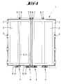
- Fig. 1 is only the dash-dotted line style Rear side of a motor vehicle body 1 shown.
- the enclosed cargo space is accessible and controlled from here via a double wing door, both of which swing doors bear the reference number 2.
- the two swing doors 2 are in the transition area hinged to the longitudinal walls of the motor vehicle body 1. There are several hinges 3 on both sides four.
- the locking lever head is 11 waxed with the rotary rod 5. Said head 11 sets continues into a latch 12. The latter works with one Closing opening 13 of the base plate 10 together.
- the locking lever 9 can be pulled on the head 11 opposite end, which forms a gripping handle 14, move from the locked position. This happens while pushing the bolt 12 against the body side Reason of the closing opening 13 and pulling out of this.
- the locking lever-side securing means is a locking member in the form of a pawl like a hammer head in profile 15. It works with one on the base plate 10 trained and so stationary counter detent 16 together.
- engagement pawl 17th In the area of influence of the pawl 15 there is a second locking element in the form of a further pawl, referred to as engagement pawl 17th
- Both the pawl 15 and the engagement pawl 17 reach behind in the closed state (Fig. 4), as it were acting as a fork latch, the counter-catch 16.
- the counter-catch 16 is realized as a basically T-shaped block.
- the body-facing T-bar has a mounting hole 18 for a retaining screw.
- the T-legs are on the other hand from the front wall of the motor vehicle body 1 clearly spaced so that they are by the pawl 15 or Engagement pawl 17 for exercising the locking or securing can be gripped over or behind.
- the pawl 15 is vertical in the installed position Axis of rotation 19 mounted.
- the engagement pawl 17th on the other hand, pivots around its own designated 20 Axis of rotation. Both axes of rotation 19, 20 extend in this way parallel to the geometric axis of the rotary rod 5.
- the rotary actuation of the engagement pawl 17 occurs via the pawl 15th encoder is on the side of the pawl 15 a trigger section 21.
- Their outside pressure actuation area is about the size of a finger.
- the driver when unlocking is an operating section 22 of the engagement pawl 17.
- the latter is located from the outside seen below the inside of the trigger section 21 and so in the area of action of the acting pawl 15.
- the pawl 15 and the engagement pawl 17 are in terms of rotation axes placed so that by appropriate stops are unable to get out of each other Extract the area of effect.
- a related one Stop, realized on locking lever 9, is at 23 designated.
- the hammer head has a lead against it well-trained pawl 15. But also the Underside of the stop 23 serves as a lock, namely in the opposite direction by a boom 24 against this Pawl 15 occurs. Reference is made to FIG. 7.
- the clear distance between the inside of the boom 24 and the lower edge of said hammer head-like projection is on the required rotation angle ranges the pawls 15, 17 matched.
- the axis of rotation on the other hand, which takes up a greater distance 19 of the pawl 15 causes their counter-latching 16 facing, other hammer head-like projection more to the side of the counter detent 16 in a larger radius arc slides off and on.
- the leads in shorter Radius held head of the engagement pawl 17 one more rotary bolt-like movement.
- the head is recognizable hook-shaped and looks like an undercut Overlap with the counter detent 16 together.
- Tensile effect on the gripping handle 14 only leads to an even more secure one Getting caught.
- there is a strong will Triggered by the pawl 15 the T-legs of the counter detent 16 also differ aligned.
- the counter-detent 16 preferably on one side for cooperation with the pawl 15 one in the direction of extension of the pivoted locking lever 9 (meaning the folding position of the locking lever) extending collar 25 as a locking shoulder.
- the counter detent 16 preferably has on the other side to interact with the engagement pawl 17 a at an acute angle to the direction of extension of the leg lever 9 extending collar 26 as a hook-like grip Blocking shoulder.
- the corresponding blocking edge 27 the hook of the engagement pawl 17 takes one in the same acute angle lying course.
- the blocking edge 27, as shown, can also have a slight curve take, with radius to the axis of rotation 20.
- Pawl 15 and engagement pawl 17 are in the direction the locking position of the espagnolette lock 4 (see FIGS. 4 and 7) spring-loaded.
- Spring 28 in the form of a torsion spring. That is in already existing intermediate area of the two in opposite directions acting jacks 15, 17 housed. The intermediate area creates a welcome spring chamber outside, covered by the leaf-like protective layer Trigger section 21 and also a part of Actuating section 22.
- the spring 28 shown in isolation in FIG. 10 consists of two coaxial, axially spaced Spiral sections 29. The closest end turns the sections 29 of the spring 28 are located in U-bracket connection.
- the U-bracket has the reference symbol 30. It forms a central spring leg, so to speak Double leg. The loads the actuating section 22nd the engagement pawl 17th
- the two outer end turns of the spiral sections 29 also sit in a feather leg away. These spring legs are designated 31.
- the spring 28 is biased.
- the spring 28 is held using the axis of rotation 19 accomplished. The latter penetrates the winding packet-like Frond sections 29. In the event of a spring break remains the functionality of the espagnolette lock 4 with regard to the double security achieved received anyway.
- the bearing surface of the operating section 22 is preferably wider than that Length of the U-bridge of the U-bracket 30.
- the other, one-legged Spring legs 31 find their abutment the troughed inside of the swiveling locking lever 9.
- the abutment in this regard is designated 32.
- Base plate 10 and the pocketed in it in the locked state Locking lever 9 are in centering, Composite to avoid relative displacement.
- This partial Interlocking takes place in the area of the head 11 of the Locking lever 9 instead.
- On the locking lever 9 is for this purpose, a three-dimensional shape 33 is formed. In which engages an exposed counter-molding 34. That is realized as a deep-drawn section of the base plate 10. It (34) forms a tabular mountain-like positioning cam.
- the sublime design 34 is lower in height than that in the immersion direction measured depth of the formation 33, so that the flanks of both of them diverging towards the base plate 10 Elements come into play. The lower one is preferred Supporting flank.
- the truncated pyramid-like structure due to the divergence Structure of the molding 33 and the counter molding 34 is irregular in its layout. So the formation points 33 a trapezoidal plan. It is on Fig. 3 referenced. This floor plan is visibly tapering in the direction of the head 11 of the locking lever 9. The same applies to the positive form of the counter-molding 34. As a supporting flank between the two forms as I said, the supportive one is chosen. So one can vibration-free locking can be brought about.
- a solution that has a favorable influence on the assembly exists still in that in the locking lever 9, assigned a fastening recess 36 in the base plate 10, a bore 37 is formed. That like the mounting hole 18 also act as a mounting hole Bore 37 is used to adjust the base plate 10 during assembly as a welcome centering point. It leaves an optimal setting of the closure-forming Introduce elements.
- a third mounting hole 38 in the base plate 10 is at the level of the closing opening 13, so that the required accessibility for the screwing tool given is.
- all fasteners are inaccessible covered by the lockable locking lever 9.
- On Lock cylinder 39 is the espagnolette 4 so assigned that he pawl with his locking cam 40 15 engages under locking. In this position the pawl 15 can be released as a trigger do not move the fork latch 15/17.
- the reference numeral 35 are pockets for receiving the free ends of a spring called the locking lever 9 of the espagnolette lock 4 in one preferred angle of rotation holds. It is placed in such a way that said locking lever easily accessible from the plane of the Swing doors 2 protrudes. The latch 12, or rather the The bolt head remains close to the door. This preferred angular position is in both directions of rotation of the locking lever 9 spring-back can be overcome. This detail is still in the Unregistered German utility model application 298 13 289 explained. In the disclosure of the application is also the content of the German Utility model application fully included, also for the purpose of claiming characteristics of these documents including this application. The turning symmetric Placement of the pocket 35 allows the Right / left use of the locking lever on the espagnolette lock.
- FIGS. 11 and 16 go beyond the pockets 35 now the spring is shown. She wears that Reference numeral 41. It is a torsion spring with a multi-turn package 42. The latter is on the free-standing intermediate section of the rotating rod 5, namely between the underside of the swing doors 2 and the top of the base plate 10. The one, parallel to the room angled to the geometric axis of the rotary rod 5 End of a spring leg 43 sits in the top pocket 35. The end of the other spring leg 44 of the spring 41 engages in a downward direction open niche 45 of the swing door 2 concerned.
- Reference numeral 41 is a torsion spring with a multi-turn package 42. The latter is on the free-standing intermediate section of the rotating rod 5, namely between the underside of the swing doors 2 and the top of the base plate 10. The one, parallel to the room angled to the geometric axis of the rotary rod 5 End of a spring leg 43 sits in the top pocket 35. The end of the other spring leg 44 of the spring 41 engages in a downward direction open
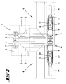
- the rotary latch 7 in the receiving pocket 8 of the upper counter-closing part 47 also with there is a freedom of movement z vertically upwards. This is not just door twists, temperature-related Shrinkage, but also temperature-related Expansion taken into account.
- the top of the rotating latch 7 can jam-free using the local Hike upwards. You come here with a few Millimeters, also in the opposite direction.
- the rotary latch 7 is a hammer head educated.
- the corresponding T shape is clear 15. That shows in detail that the upper counter-locking part 47 on one side, here on the left side again, as described for the basic version, a Receiving pocket 8 has a closing opening. That is Entry of one side 7 'of the hammer head rotary bolt 7 reserved. It is also shown that the upper Counter-closing part 47 forms a bay 48 on the other side. In which plunges the other side 7 '' of the Hammer head rotary latch 7 a. Is mirror symmetric also on the right side of the upper counter closing part 47 both the freedom of movement y vertically downwards as well as the freedom of movement z vertically upwards in taken into account in the same way.
- the free end page 7 '' ends with horizontal play in front of the one there vertical inside of bay 48; against that is corresponding position of the receiving pocket 8 on the other side left open.
- the the receiving pocket 8 forward, d. H. Ceiling that is facing away from the door surface can be seen Closed along its entire length and expanding the entrance popped up.
Landscapes
- Lock And Its Accessories (AREA)
- Power-Operated Mechanisms For Wings (AREA)
Priority Applications (2)
| Application Number | Priority Date | Filing Date | Title |
|---|---|---|---|
| DE29924647U DE29924647U1 (de) | 1998-12-22 | 1999-12-20 | Drehstangenverschluss, insbesondere für Schwenktüren von Kraftfahrzeugaufbauten |
| SI9930775T SI1013855T1 (fr) | 1998-12-22 | 1999-12-20 |
Applications Claiming Priority (4)
| Application Number | Priority Date | Filing Date | Title |
|---|---|---|---|
| DE19859382 | 1998-12-22 | ||
| DE19859382 | 1998-12-22 | ||
| DE19902249A DE19902249B4 (de) | 1998-12-22 | 1999-01-21 | Drehstangenverschluß, insbesondere für Schwenktüren von Kraftfahrzeugaufbauten |
| DE19902249 | 1999-01-21 |
Publications (3)
| Publication Number | Publication Date |
|---|---|
| EP1013855A2 true EP1013855A2 (fr) | 2000-06-28 |
| EP1013855A3 EP1013855A3 (fr) | 2000-08-30 |
| EP1013855B1 EP1013855B1 (fr) | 2005-02-09 |
Family
ID=26050954
Family Applications (1)
| Application Number | Title | Priority Date | Filing Date |
|---|---|---|---|
| EP99125388A Expired - Lifetime EP1013855B1 (fr) | 1998-12-22 | 1999-12-20 | Verrou à barre rotative notamment pour les portes pivotantes de véhicules utilitaires |
Country Status (5)
| Country | Link |
|---|---|
| EP (1) | EP1013855B1 (fr) |
| AT (1) | ATE288981T1 (fr) |
| DK (1) | DK1013855T3 (fr) |
| ES (1) | ES2237880T3 (fr) |
| PT (1) | PT1013855E (fr) |
Cited By (7)
| Publication number | Priority date | Publication date | Assignee | Title |
|---|---|---|---|---|
| FR2815661A1 (fr) * | 2000-10-24 | 2002-04-26 | Thiriet Fils | Cremone, notamment destinee a des portes de camions, remorques, conteneurs ou autres |
| EP1522664A1 (fr) * | 2003-10-10 | 2005-04-13 | Pastore & Lombardi S.r.l. | Dispositif de verrouillage à levier, notamment pour camions, remorques ou similaires |
| ES2264854A1 (es) * | 2004-07-01 | 2007-01-16 | Mecadetol, S.A. | Sistema de cierre de puertas de cajas de carga. |
| EP1785561A1 (fr) * | 2005-11-14 | 2007-05-16 | Pastore & Lombardi S.r.l. | Dispositif d'ouverture et de fermeture d'une porte d'un camion ou d'une remorque |
| EP1840304A3 (fr) * | 2006-03-29 | 2009-01-07 | F. HESTERBERG & SÖHNE GmbH & Co. KG | Verrou à barre rotative, en particulier pour portes pivotantes de superstructures de véhicules |
| EP2666940A1 (fr) * | 2012-05-21 | 2013-11-27 | Pastore & Lombardi S.r.l. | Dispositif de verrouillage de la porte des véhicules |
| US20240254805A1 (en) * | 2023-02-01 | 2024-08-01 | Powerbrace Corporation | Container door latching mechanism and related method for operating same |
Citations (1)
| Publication number | Priority date | Publication date | Assignee | Title |
|---|---|---|---|---|
| DE9419874U1 (de) | 1994-08-26 | 1996-01-04 | PWP S.A., Payerne, Waadt | Laderaumtür für z.B. einen Kastenaufbau eines LKW |
Family Cites Families (5)
| Publication number | Priority date | Publication date | Assignee | Title |
|---|---|---|---|---|
| DE2936529C2 (de) * | 1979-09-10 | 1981-05-07 | F. Hesterberg & Söhne GmbH & Co KG, 5828 Ennepetal | Betätigungsvorrichtung für einen Drehstangenverschluß |
| FR2637004A1 (fr) * | 1988-09-28 | 1990-03-30 | Pommier & Cie | Poignee de cremone a dispositif de verrouillage integre, notamment pour vehicule |
| DE9108804U1 (de) * | 1991-07-17 | 1991-10-10 | F. Hesterberg & Söhne GmbH & Co KG, 5828 Ennepetal | Verriegelungsvorrichtung für die schwenkbare Handhabe eines Drehstangenverschlusses |
| FR2708960B1 (fr) * | 1993-08-10 | 1995-12-08 | Securtir Sa | Système de verrouillage de sécurité notamment pour ouvrant de conteneur. |
| IT238234Y1 (it) * | 1997-07-22 | 2000-10-16 | Pastore & Lombardi Srl | Fermoleva per leve piatte per portelloni di camion, rimorchi o simili |
-
1999
- 1999-12-20 ES ES99125388T patent/ES2237880T3/es not_active Expired - Lifetime
- 1999-12-20 DK DK99125388T patent/DK1013855T3/da active
- 1999-12-20 EP EP99125388A patent/EP1013855B1/fr not_active Expired - Lifetime
- 1999-12-20 PT PT99125388T patent/PT1013855E/pt unknown
- 1999-12-20 AT AT99125388T patent/ATE288981T1/de active
Patent Citations (1)
| Publication number | Priority date | Publication date | Assignee | Title |
|---|---|---|---|---|
| DE9419874U1 (de) | 1994-08-26 | 1996-01-04 | PWP S.A., Payerne, Waadt | Laderaumtür für z.B. einen Kastenaufbau eines LKW |
Cited By (9)
| Publication number | Priority date | Publication date | Assignee | Title |
|---|---|---|---|---|
| FR2815661A1 (fr) * | 2000-10-24 | 2002-04-26 | Thiriet Fils | Cremone, notamment destinee a des portes de camions, remorques, conteneurs ou autres |
| EP1201854A1 (fr) * | 2000-10-24 | 2002-05-02 | Thiriet Fils Société Anonyme | Crémone, notamment destinée à des portes de camions, remorques, conteneurs ou autres |
| EP1522664A1 (fr) * | 2003-10-10 | 2005-04-13 | Pastore & Lombardi S.r.l. | Dispositif de verrouillage à levier, notamment pour camions, remorques ou similaires |
| ES2264854A1 (es) * | 2004-07-01 | 2007-01-16 | Mecadetol, S.A. | Sistema de cierre de puertas de cajas de carga. |
| ES2264854B2 (es) * | 2004-07-01 | 2007-07-01 | Mecadetol, S.A. | Sistema de cierre de puertas de cajas de carga. |
| EP1785561A1 (fr) * | 2005-11-14 | 2007-05-16 | Pastore & Lombardi S.r.l. | Dispositif d'ouverture et de fermeture d'une porte d'un camion ou d'une remorque |
| EP1840304A3 (fr) * | 2006-03-29 | 2009-01-07 | F. HESTERBERG & SÖHNE GmbH & Co. KG | Verrou à barre rotative, en particulier pour portes pivotantes de superstructures de véhicules |
| EP2666940A1 (fr) * | 2012-05-21 | 2013-11-27 | Pastore & Lombardi S.r.l. | Dispositif de verrouillage de la porte des véhicules |
| US20240254805A1 (en) * | 2023-02-01 | 2024-08-01 | Powerbrace Corporation | Container door latching mechanism and related method for operating same |
Also Published As
| Publication number | Publication date |
|---|---|
| EP1013855B1 (fr) | 2005-02-09 |
| EP1013855A3 (fr) | 2000-08-30 |
| ES2237880T3 (es) | 2005-08-01 |
| PT1013855E (pt) | 2005-06-30 |
| DK1013855T3 (da) | 2005-06-13 |
| ATE288981T1 (de) | 2005-02-15 |
Similar Documents
| Publication | Publication Date | Title |
|---|---|---|
| DE4334097C2 (de) | Gleitbefestigung | |
| EP3615749B1 (fr) | Ferrure pour fênetre ou porte | |
| DE3844849C2 (de) | Treibstangenverschluß | |
| DE2403238A1 (de) | Tuerschloss | |
| DE8909801U1 (de) | Treibstangenschloß | |
| DE102006059565A1 (de) | Schließanlage für Türen, Fenster oder dergleichen, insbesondere Treibstangenschloss mit Panikfunktion und Mehrpunktverriegelung | |
| EP2699448B1 (fr) | Dispositif de verrouillage d'un un dossier rabattable de'un siege | |
| DE102005034833A1 (de) | Verschluß mit Ratschenklinke | |
| DE3818187C1 (en) | Pivotable handle for doors, flaps or lids of vehicles | |
| DE3625227A1 (de) | Zylinderfoermiges, automatisches stehriegelschloss | |
| EP1013855A2 (fr) | Verrou à barre rotative notamment pour les portes pivotantes de véhicules utilitaires | |
| DE3538966C2 (de) | Gerätehalterung mit Sicherungseinrichtung, insbesondere Preßluftgerät-Lagerung in einem Brandschutzfahrzeug | |
| EP2107189A1 (fr) | Armature pour fenêtres ou portes | |
| EP0385213A2 (fr) | Crémone | |
| EP0361001A2 (fr) | Serrure à crochet | |
| DE102013200156A1 (de) | Beschlaganordnung | |
| DE19806154A1 (de) | Kraftfahrzeugtürverschluß | |
| DE29924647U1 (de) | Drehstangenverschluss, insbesondere für Schwenktüren von Kraftfahrzeugaufbauten | |
| EP1790809B1 (fr) | Arrêt de porte intégré dans un vantail de porte avec une boîte de serrure intégrée dans un mécanisme d'actionnement | |
| DE19902249B4 (de) | Drehstangenverschluß, insbesondere für Schwenktüren von Kraftfahrzeugaufbauten | |
| DE10145416A1 (de) | Vorrichtung zum Sichern von Ladegut auf der Ladefläche eines Fahrzeuges | |
| EP2327851B1 (fr) | Serrure avec une tige coulissante déclenchable | |
| EP0724057B1 (fr) | Poignée rotative | |
| DE29924996U1 (de) | Drehstangenverschluss, insbesondere für Schwenktüren von Kraftfahrzeugaufbauten | |
| EP0777026A1 (fr) | Ferrure d'articulation pour portes, fenêtres ou analogues oscillo-battants |
Legal Events
| Date | Code | Title | Description |
|---|---|---|---|
| PUAI | Public reference made under article 153(3) epc to a published international application that has entered the european phase |
Free format text: ORIGINAL CODE: 0009012 |
|
| AK | Designated contracting states |
Kind code of ref document: A2 Designated state(s): AT BE CH CY DE DK ES FI FR GB GR IE IT LI LU MC NL PT SE |
|
| AX | Request for extension of the european patent |
Free format text: AL;LT;LV;MK;RO;SI |
|
| PUAL | Search report despatched |
Free format text: ORIGINAL CODE: 0009013 |
|
| AK | Designated contracting states |
Kind code of ref document: A3 Designated state(s): AT BE CH CY DE DK ES FI FR GB GR IE IT LI LU MC NL PT SE |
|
| AX | Request for extension of the european patent |
Free format text: AL;LT;LV;MK;RO;SI |
|
| 17P | Request for examination filed |
Effective date: 20010222 |
|
| AKX | Designation fees paid |
Free format text: AT BE CH CY DE DK ES FI FR GB GR IE IT LI LU MC NL PT SE |
|
| AXX | Extension fees paid |
Free format text: AL PAYMENT 20010222;LT PAYMENT 20010222;LV PAYMENT 20010222;MK PAYMENT 20010222;RO PAYMENT 20010222;SI PAYMENT 20010222 |
|
| GRAP | Despatch of communication of intention to grant a patent |
Free format text: ORIGINAL CODE: EPIDOSNIGR1 |
|
| GRAS | Grant fee paid |
Free format text: ORIGINAL CODE: EPIDOSNIGR3 |
|
| GRAA | (expected) grant |
Free format text: ORIGINAL CODE: 0009210 |
|
| AK | Designated contracting states |
Kind code of ref document: B1 Designated state(s): AT BE CH CY DE DK ES FI FR GB GR IE IT LI LU MC NL PT SE |
|
| AX | Request for extension of the european patent |
Extension state: AL LT LV MK RO SI |
|
| PG25 | Lapsed in a contracting state [announced via postgrant information from national office to epo] |
Ref country code: IE Free format text: LAPSE BECAUSE OF FAILURE TO SUBMIT A TRANSLATION OF THE DESCRIPTION OR TO PAY THE FEE WITHIN THE PRESCRIBED TIME-LIMIT Effective date: 20050209 |
|
| REG | Reference to a national code |
Ref country code: GB Ref legal event code: FG4D Free format text: NOT ENGLISH |
|
| REG | Reference to a national code |
Ref country code: CH Ref legal event code: EP |
|
| REG | Reference to a national code |
Ref country code: IE Ref legal event code: FG4D Free format text: GERMAN |
|
| REF | Corresponds to: |
Ref document number: 59911595 Country of ref document: DE Date of ref document: 20050317 Kind code of ref document: P |
|
| REG | Reference to a national code |
Ref country code: GR Ref legal event code: EP Ref document number: 20050401434 Country of ref document: GR |
|
| REG | Reference to a national code |
Ref country code: SE Ref legal event code: TRGR Ref country code: CH Ref legal event code: NV Representative=s name: R. A. EGLI & CO. PATENTANWAELTE |
|
| REG | Reference to a national code |
Ref country code: DK Ref legal event code: T3 |
|
| GBT | Gb: translation of ep patent filed (gb section 77(6)(a)/1977) |
Effective date: 20050524 |
|
| REG | Reference to a national code |
Ref country code: PT Ref legal event code: SC4A Free format text: AVAILABILITY OF NATIONAL TRANSLATION Effective date: 20050509 |
|
| REG | Reference to a national code |
Ref country code: ES Ref legal event code: FG2A Ref document number: 2237880 Country of ref document: ES Kind code of ref document: T3 |
|
| REG | Reference to a national code |
Ref country code: IE Ref legal event code: FD4D |
|
| PGFP | Annual fee paid to national office [announced via postgrant information from national office to epo] |
Ref country code: GR Payment date: 20051128 Year of fee payment: 7 |
|
| PGFP | Annual fee paid to national office [announced via postgrant information from national office to epo] |
Ref country code: LU Payment date: 20051208 Year of fee payment: 7 |
|
| PLBE | No opposition filed within time limit |
Free format text: ORIGINAL CODE: 0009261 |
|
| STAA | Information on the status of an ep patent application or granted ep patent |
Free format text: STATUS: NO OPPOSITION FILED WITHIN TIME LIMIT |
|
| PG25 | Lapsed in a contracting state [announced via postgrant information from national office to epo] |
Ref country code: CY Free format text: LAPSE BECAUSE OF FAILURE TO SUBMIT A TRANSLATION OF THE DESCRIPTION OR TO PAY THE FEE WITHIN THE PRESCRIBED TIME-LIMIT Effective date: 20051220 |
|
| PG25 | Lapsed in a contracting state [announced via postgrant information from national office to epo] |
Ref country code: MC Free format text: LAPSE BECAUSE OF NON-PAYMENT OF DUE FEES Effective date: 20051231 |
|
| 26N | No opposition filed |
Effective date: 20051110 |
|
| ET | Fr: translation filed | ||
| LTLA | Lt: lapse of european patent or patent extension |
Effective date: 20061220 |
|
| PG25 | Lapsed in a contracting state [announced via postgrant information from national office to epo] |
Ref country code: LU Free format text: LAPSE BECAUSE OF NON-PAYMENT OF DUE FEES Effective date: 20061220 |
|
| PG25 | Lapsed in a contracting state [announced via postgrant information from national office to epo] |
Ref country code: GR Free format text: LAPSE BECAUSE OF NON-PAYMENT OF DUE FEES Effective date: 20070704 |
|
| PGFP | Annual fee paid to national office [announced via postgrant information from national office to epo] |
Ref country code: DK Payment date: 20101207 Year of fee payment: 12 |
|
| PGFP | Annual fee paid to national office [announced via postgrant information from national office to epo] |
Ref country code: FI Payment date: 20111223 Year of fee payment: 13 Ref country code: SE Payment date: 20111228 Year of fee payment: 13 |
|
| PGFP | Annual fee paid to national office [announced via postgrant information from national office to epo] |
Ref country code: PT Payment date: 20120124 Year of fee payment: 13 |
|
| PGFP | Annual fee paid to national office [announced via postgrant information from national office to epo] |
Ref country code: GB Payment date: 20120110 Year of fee payment: 13 |
|
| REG | Reference to a national code |
Ref country code: PT Ref legal event code: MM4A Free format text: LAPSE DUE TO NON-PAYMENT OF FEES Effective date: 20130620 |
|
| PGFP | Annual fee paid to national office [announced via postgrant information from national office to epo] |
Ref country code: ES Payment date: 20120109 Year of fee payment: 13 |
|
| PG25 | Lapsed in a contracting state [announced via postgrant information from national office to epo] |
Ref country code: SE Free format text: LAPSE BECAUSE OF NON-PAYMENT OF DUE FEES Effective date: 20121221 |
|
| REG | Reference to a national code |
Ref country code: DK Ref legal event code: EBP |
|
| GBPC | Gb: european patent ceased through non-payment of renewal fee |
Effective date: 20121220 |
|
| PG25 | Lapsed in a contracting state [announced via postgrant information from national office to epo] |
Ref country code: PT Free format text: LAPSE BECAUSE OF NON-PAYMENT OF DUE FEES Effective date: 20130620 Ref country code: FI Free format text: LAPSE BECAUSE OF NON-PAYMENT OF DUE FEES Effective date: 20121220 |
|
| REG | Reference to a national code |
Ref country code: SI Ref legal event code: KO00 Effective date: 20130726 |
|
| PG25 | Lapsed in a contracting state [announced via postgrant information from national office to epo] |
Ref country code: GB Free format text: LAPSE BECAUSE OF NON-PAYMENT OF DUE FEES Effective date: 20121220 |
|
| PG25 | Lapsed in a contracting state [announced via postgrant information from national office to epo] |
Ref country code: DK Free format text: LAPSE BECAUSE OF NON-PAYMENT OF DUE FEES Effective date: 20130102 |
|
| REG | Reference to a national code |
Ref country code: ES Ref legal event code: FD2A Effective date: 20140307 |
|
| PG25 | Lapsed in a contracting state [announced via postgrant information from national office to epo] |
Ref country code: ES Free format text: LAPSE BECAUSE OF NON-PAYMENT OF DUE FEES Effective date: 20121221 |
|
| PGFP | Annual fee paid to national office [announced via postgrant information from national office to epo] |
Ref country code: AT Payment date: 20141205 Year of fee payment: 16 Ref country code: FR Payment date: 20141204 Year of fee payment: 16 |
|
| PGFP | Annual fee paid to national office [announced via postgrant information from national office to epo] |
Ref country code: BE Payment date: 20141212 Year of fee payment: 16 |
|
| PGFP | Annual fee paid to national office [announced via postgrant information from national office to epo] |
Ref country code: CH Payment date: 20151209 Year of fee payment: 17 |
|
| PGFP | Annual fee paid to national office [announced via postgrant information from national office to epo] |
Ref country code: NL Payment date: 20151217 Year of fee payment: 17 |
|
| PG25 | Lapsed in a contracting state [announced via postgrant information from national office to epo] |
Ref country code: BE Free format text: LAPSE BECAUSE OF NON-PAYMENT OF DUE FEES Effective date: 20151231 |
|
| REG | Reference to a national code |
Ref country code: AT Ref legal event code: MM01 Ref document number: 288981 Country of ref document: AT Kind code of ref document: T Effective date: 20151220 |
|
| REG | Reference to a national code |
Ref country code: FR Ref legal event code: ST Effective date: 20160831 |
|
| PG25 | Lapsed in a contracting state [announced via postgrant information from national office to epo] |
Ref country code: FR Free format text: LAPSE BECAUSE OF NON-PAYMENT OF DUE FEES Effective date: 20151231 Ref country code: AT Free format text: LAPSE BECAUSE OF NON-PAYMENT OF DUE FEES Effective date: 20151220 |
|
| PGFP | Annual fee paid to national office [announced via postgrant information from national office to epo] |
Ref country code: DE Payment date: 20161214 Year of fee payment: 18 |
|
| PGFP | Annual fee paid to national office [announced via postgrant information from national office to epo] |
Ref country code: IT Payment date: 20161229 Year of fee payment: 18 |
|
| REG | Reference to a national code |
Ref country code: CH Ref legal event code: PL |
|
| REG | Reference to a national code |
Ref country code: NL Ref legal event code: MM Effective date: 20170101 |
|
| PG25 | Lapsed in a contracting state [announced via postgrant information from national office to epo] |
Ref country code: NL Free format text: LAPSE BECAUSE OF NON-PAYMENT OF DUE FEES Effective date: 20170101 |
|
| PG25 | Lapsed in a contracting state [announced via postgrant information from national office to epo] |
Ref country code: LI Free format text: LAPSE BECAUSE OF NON-PAYMENT OF DUE FEES Effective date: 20161231 Ref country code: CH Free format text: LAPSE BECAUSE OF NON-PAYMENT OF DUE FEES Effective date: 20161231 |
|
| REG | Reference to a national code |
Ref country code: DE Ref legal event code: R119 Ref document number: 59911595 Country of ref document: DE |
|
| PG25 | Lapsed in a contracting state [announced via postgrant information from national office to epo] |
Ref country code: DE Free format text: LAPSE BECAUSE OF NON-PAYMENT OF DUE FEES Effective date: 20180703 Ref country code: IT Free format text: LAPSE BECAUSE OF NON-PAYMENT OF DUE FEES Effective date: 20171220 |