EP1013884B1 - Aube de turbine avec plateforme refroidie - Google Patents
Aube de turbine avec plateforme refroidie Download PDFInfo
- Publication number
- EP1013884B1 EP1013884B1 EP99811187A EP99811187A EP1013884B1 EP 1013884 B1 EP1013884 B1 EP 1013884B1 EP 99811187 A EP99811187 A EP 99811187A EP 99811187 A EP99811187 A EP 99811187A EP 1013884 B1 EP1013884 B1 EP 1013884B1
- Authority
- EP
- European Patent Office
- Prior art keywords
- cooling
- turbine blade
- shroud
- shroud band
- blade according
- Prior art date
- Legal status (The legal status is an assumption and is not a legal conclusion. Google has not performed a legal analysis and makes no representation as to the accuracy of the status listed.)
- Expired - Lifetime
Links
Images


Classifications
-
- F—MECHANICAL ENGINEERING; LIGHTING; HEATING; WEAPONS; BLASTING
- F01—MACHINES OR ENGINES IN GENERAL; ENGINE PLANTS IN GENERAL; STEAM ENGINES
- F01D—NON-POSITIVE DISPLACEMENT MACHINES OR ENGINES, e.g. STEAM TURBINES
- F01D5/00—Blades; Blade-carrying members; Heating, heat-insulating, cooling or antivibration means on the blades or the members
- F01D5/12—Blades
- F01D5/22—Blade-to-blade connections, e.g. for damping vibrations
- F01D5/225—Blade-to-blade connections, e.g. for damping vibrations by shrouding
-
- F—MECHANICAL ENGINEERING; LIGHTING; HEATING; WEAPONS; BLASTING
- F01—MACHINES OR ENGINES IN GENERAL; ENGINE PLANTS IN GENERAL; STEAM ENGINES
- F01D—NON-POSITIVE DISPLACEMENT MACHINES OR ENGINES, e.g. STEAM TURBINES
- F01D5/00—Blades; Blade-carrying members; Heating, heat-insulating, cooling or antivibration means on the blades or the members
- F01D5/12—Blades
- F01D5/14—Form or construction
- F01D5/18—Hollow blades, i.e. blades with cooling or heating channels or cavities; Heating, heat-insulating or cooling means on blades
- F01D5/187—Convection cooling
-
- F—MECHANICAL ENGINEERING; LIGHTING; HEATING; WEAPONS; BLASTING
- F05—INDEXING SCHEMES RELATING TO ENGINES OR PUMPS IN VARIOUS SUBCLASSES OF CLASSES F01-F04
- F05B—INDEXING SCHEME RELATING TO WIND, SPRING, WEIGHT, INERTIA OR LIKE MOTORS, TO MACHINES OR ENGINES FOR LIQUIDS COVERED BY SUBCLASSES F03B, F03D AND F03G
- F05B2240/00—Components
- F05B2240/80—Platforms for stationary or moving blades
- F05B2240/801—Platforms for stationary or moving blades cooled platforms
-
- F—MECHANICAL ENGINEERING; LIGHTING; HEATING; WEAPONS; BLASTING
- F05—INDEXING SCHEMES RELATING TO ENGINES OR PUMPS IN VARIOUS SUBCLASSES OF CLASSES F01-F04
- F05D—INDEXING SCHEME FOR ASPECTS RELATING TO NON-POSITIVE-DISPLACEMENT MACHINES OR ENGINES, GAS-TURBINES OR JET-PROPULSION PLANTS
- F05D2240/00—Components
- F05D2240/80—Platforms for stationary or moving blades
- F05D2240/81—Cooled platforms
Definitions
- the present invention relates to the field of gas turbines. It concerns an air cooled turbine blade which is perpendicular to the blade tip Has to the blade longitudinal axis extending shroud element, wherein the shroud element for the purpose of cooling a plurality of cooling holes is traversed, which input side with at least one through the Turbine blade to the blade tip extending cooling air duct in conjunction stand and on the output side in the outer space surrounding the turbine blade lead.
- the basic idea of the invention consists in the side edges of the shroud elements To arrange recesses into which the cooling holes open.
- the recesses of opposite shroud elements form a Gap.
- the cooling air is divided into two partial flows. One Part flows to the top and feeds a cavity between the spaced ones Sealing ribs.
- the other part flows to the shroud bottom and mixes there with the hot gases under adjustment of a mixing temperature, which is the thermal Reduced load in this area. Due to the gap geometry, the ratio the up and down flowing subsets influenced.
- Cooling holes Means for improving the heat transfer between cooling air and shroud element are proposed.
- the means for improving the heat transfer at the bore walls can Roughnesses, ribs and / or turbulators include.
- the drilling can be done by means of the so-called “STEM drilling” process to be created.
- STEM drilling for example, in the US-A-5,306,401 in connection with the manufacture of cooling holes in turbine blades has been described, can be easily and reliably cooling holes produce with improved heat transfer properties.
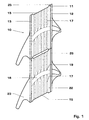
- a preferred embodiment of a turbine blade according to the invention is shown in plan view.
- the turbine blade 10 comprises the actual blade profile 23 and a shroud element 11 arranged transversely thereto on the blade tip, which together with the shroud elements of the other blades (not shown) results in a continuous, mechanically stabilizing shroud.
- the blade profile 23 is partially hollow in the interior and traversed by one or more cooling air channels 18, which guide cooling air from the blade root to the blade tip.
- the shroud element 11 has on its upper side 22 two parallel running in the direction of movement of the blade tip sealing ribs 12 and 13, which together with the opposite housing wall 20 of the gas turbine form a connected by gaps with the environment cavity 21.
- cooling holes 17 Inside the shroud element 11 extend between and substantially parallel to the ribs 12, 13 a plurality of cooling holes 17, starting from the center to the outside.
- the cooling holes 17 are on the input side with the cooling air duct 18 in connection and are supplied by this with cooling air.
- the cooling holes 17 do not extend entirely to the lateral end or edge of the shroud element 11, but each open from the side into an elongated, recessed on the top 22 in the shroud element 11 recess 15th Es It is conceivable that the cooling bores 17 run slightly obliquely and deviate from one another by parallelism, if it is necessary to optimize the cooling over the entire surface of the shroud element 11.
- the cooling holes 17 in the cooling arrangement shown are preferably manufactured using the so-called "STEM drilling" method described in the US Pat 5,306,401 is described in detail. This is what it is (through change the feed), the surface of the cooling holes 17 with roughness, Equip ribs or turbulators. This leads to a significantly more efficient Cooling, because the shape of the cooling hole can be optimized. Farther it is advantageous, the cooling holes 17, preferably on the input side, i. in the area the cooling air supply to the profile 23, each with a throttle point 19 equip. This makes it possible to selectively limit the cooling air mass flow and to obtain a much more efficient cooling.
- the embodiment according to FIG. 2 differs from that according to FIG. 1 in that the cooling bores 17 are designed as diffuser 16a or diffuser-like from the throttle point 19, which is arranged respectively on the inlet side of each cooling bore.
- the cooling holes have an oval configuration. This increases, like the equipment with internal roughness or the diffuser-like extension, the effective surface area available for heat transfer.
- the cooling holes 17 may additionally or alternatively have other configurations than those described above. As such, for example, regularly or irregularly held depressions or corrugations are conceivable.
- the side edges 25 of the shroud elements 11 but designed so that adjacent elements 11 are only partially in contact, the area of the exiting cooling holes but is withdrawn in contrast in a depression. Between the adjacent elements, the opposite recesses 15 form gaps 26 into which the cooling air enters.
- This embodiment reliably prevents closure of the mouths by adjacent shroud elements. It ensures that the cooling air can always pass through the cooling holes 17, even if two adjacent shroud elements 11 are in mechanical contact. The cooling air entering from the two adjacent elements 11 into the gap 26 is divided into two partial flows.
- a partial flow flows upward and leads to an inflation of the cavity 21 above the shroud and thus contributes to a reduction of the penetrating mass flow of hot gas 24, while the other partial flow reaches the underside of the shroud and there mixes with the hot gases.
- the resulting mixing temperature reduces the thermal load in this area. Due to the structural design of the gap, the quantitative ratio of the two partial flows can be influenced. Thus, the upper and lower sides can have a different gap width or the boundary walls can be inclined or fluidically designed differently.
Landscapes
- Engineering & Computer Science (AREA)
- Mechanical Engineering (AREA)
- General Engineering & Computer Science (AREA)
- Turbine Rotor Nozzle Sealing (AREA)
Claims (9)
- Aube de turbine refroidie à l'air (10), qui présente à la tête de l'aube un élément de plateforme (11) s'étendant perpendiculairement à l'axe longitudinal de l'aube, dans laquelle l'élément de plateforme (11) est parcouru par une pluralité de passages de refroidissement (17) pour son refroidissement, qui sont en communication du côté de l'entrée avec au moins un canal de refroidissement (18) s'étendant à travers l'aube de turbine (10) jusqu'à la tête de l'aube, et qui débouchent du côté de la sortie dans une chambre extérieure entourant l'aube de turbine (10), dans laquelle les passages de refroidissement (17) s'étendent de l'intérieur vers l'extérieur dans l'élément de plateforme (11) au moins approximativement parallèlement à la direction de mouvement de l'aube (10) et débouchent chacun avant le bord extérieur (25) de l'élément de plateforme (11) dans un enfoncement de surface (15) ouvert vers la chambre extérieure, l'enfoncement (15) ouvert vers la chambre extérieure étant disposé sur le côté latéral (25) de l'élément de plateforme (11), il est prévu sur la face supérieure (22) de l'élément de plateforme (11) au moins deux nervures d'étanchéité (12, 13) espacées l'une de l'autre et s'étendant parallèlement à la direction de mouvement de l'aube, qui forment une cavité (21) en coopération avec la paroi opposée (20) de l'enceinte de la turbine à gaz, les passages de refroidissement (17) débouchent dans une fente (26) formée par des enfoncements (15) opposés, et au moins un courant partiel de l'air de refroidissement sortant ici pénètre dans la cavité (21), caractérisée en ce que le rapport des débits des courants partiels sortant hors de la fente (26) en direction de la face supérieure de la plateforme et de la face inférieure de la plateforme est commandé par la géométrie de la fente.
- Aube de turbine selon la revendication 1, caractérisée en ce que la face supérieure et la face inférieure présentent une largeur de fente différente.
- Aube de turbine selon la revendication 1, caractérisée en ce qu'il est prévu dans les passages de refroidissement (17) des moyens pour améliorer le transfert de chaleur entre l'air de refroidissement et l'élément de plateforme (11).
- Aube de turbine selon la revendication 3, caractérisée en ce que les moyens pour améliorer le transfert de chaleur comprennent des aspérités, des nervures et/ou des chicanes sur les parois des passages (17).
- Aube de turbine selon la revendication 4, caractérisée en ce que les passages de refroidissement (17) sont réalisés par le procédé dit de "STEM drilling" [perçage par usinage électrolytique].
- Aube de turbine selon la revendication 1, caractérisée en ce qu'il est prévu dans les passages de refroidissement (17) chaque fois un point d'étranglement (19) pour limiter le débit massique d'air de refroidissement.
- Aube de turbine selon la revendication 6, caractérisée en ce que les points d'étranglement (19) sont chaque fois disposés du côté de l'entrée des passages de refroidissement (17).
- Aube de turbine selon la revendication 1, caractérisée en ce que les passages de refroidissement (17) présentent une section transversale ovale.
- Aube de turbine selon la revendication 1, caractérisée en ce que les passages de refroidissement (17) forment un diffuseur ou ont une forme de diffuseur dans le sens de l'écoulement.
Applications Claiming Priority (4)
| Application Number | Priority Date | Filing Date | Title |
|---|---|---|---|
| DE19860245 | 1998-12-24 | ||
| DE19860244 | 1998-12-24 | ||
| DE19860245A DE19860245A1 (de) | 1998-12-24 | 1998-12-24 | Turbinenschaufel mit aktiv gekühltem Deckbandelement |
| DE19860244A DE19860244B4 (de) | 1998-12-24 | 1998-12-24 | Turbinenschaufel mit aktiv gekühltem Deckbandelement |
Publications (3)
| Publication Number | Publication Date |
|---|---|
| EP1013884A2 EP1013884A2 (fr) | 2000-06-28 |
| EP1013884A3 EP1013884A3 (fr) | 2003-11-05 |
| EP1013884B1 true EP1013884B1 (fr) | 2005-07-27 |
Family
ID=26051058
Family Applications (1)
| Application Number | Title | Priority Date | Filing Date |
|---|---|---|---|
| EP99811187A Expired - Lifetime EP1013884B1 (fr) | 1998-12-24 | 1999-12-21 | Aube de turbine avec plateforme refroidie |
Country Status (4)
| Country | Link |
|---|---|
| US (1) | US6340284B1 (fr) |
| EP (1) | EP1013884B1 (fr) |
| CN (1) | CN1260442A (fr) |
| DE (1) | DE59912323D1 (fr) |
Families Citing this family (40)
| Publication number | Priority date | Publication date | Assignee | Title |
|---|---|---|---|---|
| EP1041247B1 (fr) | 1999-04-01 | 2012-08-01 | General Electric Company | Aube de turbineà gaz comprenant un circuit de refroidissement ouvert |
| US6761534B1 (en) | 1999-04-05 | 2004-07-13 | General Electric Company | Cooling circuit for a gas turbine bucket and tip shroud |
| US6254345B1 (en) * | 1999-09-07 | 2001-07-03 | General Electric Company | Internally cooled blade tip shroud |
| DE19963377A1 (de) * | 1999-12-28 | 2001-07-12 | Abb Alstom Power Ch Ag | Turbinenschaufel mit aktiv gekühltem Deckbandelement |
| US6471480B1 (en) * | 2001-04-16 | 2002-10-29 | United Technologies Corporation | Thin walled cooled hollow tip shroud |
| JP2002371802A (ja) * | 2001-06-14 | 2002-12-26 | Mitsubishi Heavy Ind Ltd | ガスタービンにおけるシュラウド一体型動翼と分割環 |
| US6632069B1 (en) * | 2001-10-02 | 2003-10-14 | Oleg Naljotov | Step of pressure of the steam and gas turbine with universal belt |
| US20040101410A1 (en) * | 2001-10-02 | 2004-05-27 | Oleg Naljotov | Axial flow fluid machine |
| US6491498B1 (en) * | 2001-10-04 | 2002-12-10 | Power Systems Mfg, Llc. | Turbine blade pocket shroud |
| US7074006B1 (en) | 2002-10-08 | 2006-07-11 | The United States Of America As Represented By The Administrator Of National Aeronautics And Space Administration | Endwall treatment and method for gas turbine |
| CN100386502C (zh) * | 2003-04-18 | 2008-05-07 | 奥莱格·耐尔卓托夫 | 具有改进的罩或密封件的蒸汽/气体涡轮机 |
| US7094023B2 (en) * | 2004-02-09 | 2006-08-22 | United Technologies Corporation | Shroud honeycomb cutter |
| US7066714B2 (en) * | 2004-03-26 | 2006-06-27 | United Technologies Corporation | High speed rotor assembly shroud |
| EP1591626A1 (fr) | 2004-04-30 | 2005-11-02 | Alstom Technology Ltd | Aube de turbine à gaz |
| KR100758725B1 (ko) | 2005-10-17 | 2007-09-14 | 올레지 날조토브 | 유니버설 쉬라우드를 구비한 증기/가스 터빈 압력 단 |
| US7568882B2 (en) * | 2007-01-12 | 2009-08-04 | General Electric Company | Impingement cooled bucket shroud, turbine rotor incorporating the same, and cooling method |
| US7938951B2 (en) * | 2007-03-22 | 2011-05-10 | General Electric Company | Methods and systems for forming tapered cooling holes |
| US20080230396A1 (en) * | 2007-03-22 | 2008-09-25 | General Electric Company | Methods and systems for forming turbulated cooling holes |
| US7964087B2 (en) * | 2007-03-22 | 2011-06-21 | General Electric Company | Methods and systems for forming cooling holes having circular inlets and non-circular outlets |
| US7946816B2 (en) * | 2008-01-10 | 2011-05-24 | General Electric Company | Turbine blade tip shroud |
| US7946817B2 (en) * | 2008-01-10 | 2011-05-24 | General Electric Company | Turbine blade tip shroud |
| US8057177B2 (en) * | 2008-01-10 | 2011-11-15 | General Electric Company | Turbine blade tip shroud |
| US20090180894A1 (en) * | 2008-01-10 | 2009-07-16 | General Electric Company | Turbine blade tip shroud |
| US8317461B2 (en) * | 2008-08-27 | 2012-11-27 | United Technologies Corporation | Gas turbine engine component having dual flow passage cooling chamber formed by single core |
| GB0901129D0 (en) * | 2009-01-26 | 2009-03-11 | Rolls Royce Plc | Rotor blade |
| CH700686A1 (de) * | 2009-03-30 | 2010-09-30 | Alstom Technology Ltd | Schaufel für eine gasturbine. |
| GB0910177D0 (en) * | 2009-06-15 | 2009-07-29 | Rolls Royce Plc | A cooled component for a gas turbine engine |
| US8353669B2 (en) * | 2009-08-18 | 2013-01-15 | United Technologies Corporation | Turbine vane platform leading edge cooling holes |
| DE102009049649A1 (de) * | 2009-10-15 | 2011-04-21 | Abb Turbo Systems Ag | Turbinenrad |
| JP5517910B2 (ja) * | 2010-12-22 | 2014-06-11 | 三菱重工業株式会社 | タービン、及びシール構造 |
| US20140064984A1 (en) * | 2012-08-31 | 2014-03-06 | General Electric Company | Cooling arrangement for platform region of turbine rotor blade |
| JP5612136B2 (ja) | 2013-01-09 | 2014-10-22 | ファナック株式会社 | 複数の直線により形状が定義されるインペラの形成方法およびインペラ |
| US9759070B2 (en) * | 2013-08-28 | 2017-09-12 | General Electric Company | Turbine bucket tip shroud |
| US20160169001A1 (en) * | 2013-09-26 | 2016-06-16 | United Technologies Corporation | Diffused platform cooling holes |
| US10301967B2 (en) * | 2013-10-21 | 2019-05-28 | United Technologies Corporation | Incident tolerant turbine vane gap flow discouragement |
| US10539026B2 (en) | 2017-09-21 | 2020-01-21 | United Technologies Corporation | Gas turbine engine component with cooling holes having variable roughness |
| US10641108B2 (en) * | 2018-04-06 | 2020-05-05 | United Technologies Corporation | Turbine blade shroud for gas turbine engine with power turbine and method of manufacturing same |
| JP7477284B2 (ja) * | 2019-11-14 | 2024-05-01 | 三菱重工業株式会社 | タービン翼及びガスタービン |
| US11255198B1 (en) * | 2021-06-10 | 2022-02-22 | General Electric Company | Tip shroud with exit surface for cooling passages |
| CN115324657A (zh) * | 2022-10-12 | 2022-11-11 | 中国航发四川燃气涡轮研究院 | 涡轮工作叶片叶冠冷却结构 |
Family Cites Families (23)
| Publication number | Priority date | Publication date | Assignee | Title |
|---|---|---|---|---|
| US3527544A (en) * | 1968-12-12 | 1970-09-08 | Gen Motors Corp | Cooled blade shroud |
| GB1423833A (en) | 1972-04-20 | 1976-02-04 | Rolls Royce | Rotor blades for fluid flow machines |
| US3816022A (en) | 1972-09-01 | 1974-06-11 | Gen Electric | Power augmenter bucket tip construction for open-circuit liquid cooled turbines |
| GB1605335A (en) * | 1975-08-23 | 1991-12-18 | Rolls Royce | A rotor blade for a gas turbine engine |
| US4177011A (en) | 1976-04-21 | 1979-12-04 | General Electric Company | Bar for sealing the gap between adjacent shroud plates in liquid-cooled gas turbine |
| JPS5847104A (ja) * | 1981-09-11 | 1983-03-18 | Agency Of Ind Science & Technol | ガスタ−ビンのタ−ビン動翼 |
| US5003766A (en) * | 1984-10-10 | 1991-04-02 | Paul Marius A | Gas turbine engine |
| US4902198A (en) * | 1988-08-31 | 1990-02-20 | Westinghouse Electric Corp. | Apparatus for film cooling of turbine van shrouds |
| GB2223276B (en) * | 1988-09-30 | 1992-09-02 | Rolls Royce Plc | Turbine aerofoil blade |
| GB2228540B (en) * | 1988-12-07 | 1993-03-31 | Rolls Royce Plc | Cooling of turbine blades |
| JPH03182602A (ja) * | 1989-12-08 | 1991-08-08 | Hitachi Ltd | 冷却流路を有するガスタービン翼及びその冷却流路の加工方法 |
| US5122033A (en) * | 1990-11-16 | 1992-06-16 | Paul Marius A | Turbine blade unit |
| JP3260437B2 (ja) * | 1992-09-03 | 2002-02-25 | 株式会社日立製作所 | ガスタービン及びガスタービンの段落装置 |
| GB9224241D0 (en) | 1992-11-19 | 1993-01-06 | Bmw Rolls Royce Gmbh | A turbine blade arrangement |
| US5306401A (en) * | 1993-03-15 | 1994-04-26 | Fierkens Richard H J | Method for drilling cooling holes in turbine blades |
| GB2290833B (en) | 1994-07-02 | 1998-08-05 | Rolls Royce Plc | Turbine blade |
| US5482435A (en) | 1994-10-26 | 1996-01-09 | Westinghouse Electric Corporation | Gas turbine blade having a cooled shroud |
| GB2298246B (en) * | 1995-02-23 | 1998-10-28 | Bmw Rolls Royce Gmbh | A turbine-blade arrangement comprising a shroud band |
| JP3182602B2 (ja) | 1995-03-31 | 2001-07-03 | 矢崎総業株式会社 | 吸収冷温水機とその制御方法 |
| US5785496A (en) | 1997-02-24 | 1998-07-28 | Mitsubishi Heavy Industries, Ltd. | Gas turbine rotor |
| JPH10266803A (ja) | 1997-03-25 | 1998-10-06 | Mitsubishi Heavy Ind Ltd | ガスタービン冷却動翼 |
| JPH1113402A (ja) * | 1997-06-23 | 1999-01-19 | Mitsubishi Heavy Ind Ltd | ガスタービン冷却翼チップシュラウド |
| EP0935052B1 (fr) * | 1998-02-04 | 2006-05-03 | Mitsubishi Heavy Industries, Ltd. | Aube rotorique pour turbine à gaz |
-
1999
- 1999-12-21 DE DE59912323T patent/DE59912323D1/de not_active Expired - Lifetime
- 1999-12-21 EP EP99811187A patent/EP1013884B1/fr not_active Expired - Lifetime
- 1999-12-23 US US09/471,410 patent/US6340284B1/en not_active Expired - Lifetime
- 1999-12-24 CN CN99124987A patent/CN1260442A/zh active Pending
Also Published As
| Publication number | Publication date |
|---|---|
| CN1260442A (zh) | 2000-07-19 |
| EP1013884A3 (fr) | 2003-11-05 |
| US6340284B1 (en) | 2002-01-22 |
| EP1013884A2 (fr) | 2000-06-28 |
| DE59912323D1 (de) | 2005-09-01 |
Similar Documents
| Publication | Publication Date | Title |
|---|---|---|
| EP1013884B1 (fr) | Aube de turbine avec plateforme refroidie | |
| DE19944923B4 (de) | Turbinenschaufel für den Rotor einer Gasturbine | |
| DE10001109B4 (de) | Gekühlte Schaufel für eine Gasturbine | |
| EP1126136B1 (fr) | Aube de turbine avec carenage d'extremité refroidie | |
| DE60018817T2 (de) | Gekühlte Gasturbinenschaufel | |
| DE3711024C2 (de) | Turbinenleitschaufel für ein Gasturbinentriebwerk | |
| DE2930949C2 (fr) | ||
| DE69302614T2 (de) | Gekühlte Schaufel für eine Turbomaschine | |
| DE69210862T2 (de) | Turbinenschaufel mit Luftfilmkühlungsbohrungen mit mehreren Auslässen | |
| DE3211139C1 (de) | Axialturbinenschaufel,insbesondere Axialturbinenlaufschaufel fuer Gasturbinentriebwerke | |
| DE102012100266B4 (de) | Gekrümmte Kühlkanäle für eine Turbinenkomponente | |
| DE69017493T2 (de) | Gekühlte Turbinenschaufel und Kombinationskraftwerk mit einer Gasturbine, die solche Schaufeln hat. | |
| DE102004003354B4 (de) | Turbinen-Laufschaufel und Gasturbine | |
| DE69811624T2 (de) | Gasturbinenrotorschaufel | |
| DE102006004437A1 (de) | Plattform einer Laufschaufel einer Gasturbine, Verfahren zur Herstellung einer Laufschaufel, Dichtungsplatte und Gasturbine | |
| DE1946535B2 (de) | Bauteil für ein Gasturbinentriebwerk | |
| CH698339B1 (de) | Turbinenschaufel mit gekühltem Deckband. | |
| EP1207268B1 (fr) | Aube de turbine à gaz et procédé de fabrication d'une aube de turbine à gaz | |
| DE102008055590A1 (de) | Turbinenschaufel-Deckband | |
| DE19904229A1 (de) | Gekühlte Turbinenschaufel | |
| EP3207217B1 (fr) | Composant de turbine à gaz refroidi par couche d'air | |
| EP1006263A1 (fr) | Refroidissement d'aube | |
| EP1431662B1 (fr) | Chambre de combustion de turbine avec système de refroidissement à circuit fermé | |
| DE2643049A1 (de) | Schaufel mit gekuehlter plattform fuer eine stroemungsmaschine | |
| DE10331635B4 (de) | Gekühlte Schaufel für eine Gasturbine |
Legal Events
| Date | Code | Title | Description |
|---|---|---|---|
| PUAI | Public reference made under article 153(3) epc to a published international application that has entered the european phase |
Free format text: ORIGINAL CODE: 0009012 |
|
| AK | Designated contracting states |
Kind code of ref document: A2 Designated state(s): AT BE CH CY DE DK ES FI FR GB GR IE IT LI LU MC NL PT SE |
|
| AX | Request for extension of the european patent |
Free format text: AL;LT;LV;MK;RO;SI |
|
| RAP1 | Party data changed (applicant data changed or rights of an application transferred) |
Owner name: ALSTOM |
|
| RAP1 | Party data changed (applicant data changed or rights of an application transferred) |
Owner name: ALSTOM (SWITZERLAND) LTD |
|
| PUAL | Search report despatched |
Free format text: ORIGINAL CODE: 0009013 |
|
| AK | Designated contracting states |
Kind code of ref document: A3 Designated state(s): AT BE CH CY DE DK ES FI FR GB GR IE IT LI LU MC NL PT SE |
|
| AX | Request for extension of the european patent |
Extension state: AL LT LV MK RO SI |
|
| RAP1 | Party data changed (applicant data changed or rights of an application transferred) |
Owner name: ALSTOM TECHNOLOGY LTD |
|
| 17P | Request for examination filed |
Effective date: 20040430 |
|
| AKX | Designation fees paid |
Designated state(s): DE FR GB |
|
| 17Q | First examination report despatched |
Effective date: 20040709 |
|
| GRAP | Despatch of communication of intention to grant a patent |
Free format text: ORIGINAL CODE: EPIDOSNIGR1 |
|
| GRAS | Grant fee paid |
Free format text: ORIGINAL CODE: EPIDOSNIGR3 |
|
| GRAA | (expected) grant |
Free format text: ORIGINAL CODE: 0009210 |
|
| AK | Designated contracting states |
Kind code of ref document: B1 Designated state(s): DE FR GB |
|
| REG | Reference to a national code |
Ref country code: GB Ref legal event code: FG4D Free format text: NOT ENGLISH |
|
| REF | Corresponds to: |
Ref document number: 59912323 Country of ref document: DE Date of ref document: 20050901 Kind code of ref document: P |
|
| GBT | Gb: translation of ep patent filed (gb section 77(6)(a)/1977) |
Effective date: 20050917 |
|
| ET | Fr: translation filed | ||
| PLBE | No opposition filed within time limit |
Free format text: ORIGINAL CODE: 0009261 |
|
| STAA | Information on the status of an ep patent application or granted ep patent |
Free format text: STATUS: NO OPPOSITION FILED WITHIN TIME LIMIT |
|
| 26N | No opposition filed |
Effective date: 20060428 |
|
| REG | Reference to a national code |
Ref country code: FR Ref legal event code: PLFP Year of fee payment: 17 |
|
| REG | Reference to a national code |
Ref country code: DE Ref legal event code: R082 Ref document number: 59912323 Country of ref document: DE Representative=s name: ROESLER, UWE, DIPL.-PHYS.UNIV., DE Ref country code: DE Ref legal event code: R081 Ref document number: 59912323 Country of ref document: DE Owner name: ANSALDO ENERGIA IP UK LIMITED, GB Free format text: FORMER OWNER: ALSTOM TECHNOLOGY LTD., BADEN, CH Ref country code: DE Ref legal event code: R081 Ref document number: 59912323 Country of ref document: DE Owner name: GENERAL ELECTRIC TECHNOLOGY GMBH, CH Free format text: FORMER OWNER: ALSTOM TECHNOLOGY LTD., BADEN, CH |
|
| REG | Reference to a national code |
Ref country code: FR Ref legal event code: CD Owner name: ALSTOM TECHNOLOGY LTD, CH Effective date: 20161110 |
|
| REG | Reference to a national code |
Ref country code: FR Ref legal event code: PLFP Year of fee payment: 18 |
|
| PGFP | Annual fee paid to national office [announced via postgrant information from national office to epo] |
Ref country code: DE Payment date: 20161213 Year of fee payment: 18 Ref country code: GB Payment date: 20161222 Year of fee payment: 18 |
|
| PGFP | Annual fee paid to national office [announced via postgrant information from national office to epo] |
Ref country code: FR Payment date: 20161222 Year of fee payment: 18 |
|
| REG | Reference to a national code |
Ref country code: DE Ref legal event code: R082 Ref document number: 59912323 Country of ref document: DE Representative=s name: ROESLER, UWE, DIPL.-PHYS.UNIV., DE Ref country code: DE Ref legal event code: R081 Ref document number: 59912323 Country of ref document: DE Owner name: ANSALDO ENERGIA IP UK LIMITED, GB Free format text: FORMER OWNER: GENERAL ELECTRIC TECHNOLOGY GMBH, BADEN, CH |
|
| REG | Reference to a national code |
Ref country code: GB Ref legal event code: 732E Free format text: REGISTERED BETWEEN 20170824 AND 20170830 |
|
| REG | Reference to a national code |
Ref country code: FR Ref legal event code: TP Owner name: ANSALDO ENERGIA IP UK LIMITED, GB Effective date: 20171221 |
|
| REG | Reference to a national code |
Ref country code: DE Ref legal event code: R119 Ref document number: 59912323 Country of ref document: DE |
|
| GBPC | Gb: european patent ceased through non-payment of renewal fee |
Effective date: 20171221 |
|
| REG | Reference to a national code |
Ref country code: FR Ref legal event code: ST Effective date: 20180831 |
|
| PG25 | Lapsed in a contracting state [announced via postgrant information from national office to epo] |
Ref country code: FR Free format text: LAPSE BECAUSE OF NON-PAYMENT OF DUE FEES Effective date: 20180102 Ref country code: DE Free format text: LAPSE BECAUSE OF NON-PAYMENT OF DUE FEES Effective date: 20180703 |
|
| PG25 | Lapsed in a contracting state [announced via postgrant information from national office to epo] |
Ref country code: GB Free format text: LAPSE BECAUSE OF NON-PAYMENT OF DUE FEES Effective date: 20171221 |