EP1013888A2 - Montagemethode für eine Turbomaschine - Google Patents
Montagemethode für eine Turbomaschine Download PDFInfo
- Publication number
- EP1013888A2 EP1013888A2 EP99310395A EP99310395A EP1013888A2 EP 1013888 A2 EP1013888 A2 EP 1013888A2 EP 99310395 A EP99310395 A EP 99310395A EP 99310395 A EP99310395 A EP 99310395A EP 1013888 A2 EP1013888 A2 EP 1013888A2
- Authority
- EP
- European Patent Office
- Prior art keywords
- rotor
- assembly
- seal land
- assembling
- seal
- Prior art date
- Legal status (The legal status is an assumption and is not a legal conclusion. Google has not performed a legal analysis and makes no representation as to the accuracy of the status listed.)
- Granted
Links
- 238000000034 method Methods 0.000 title claims abstract description 34
- 238000010276 construction Methods 0.000 claims abstract description 3
- 239000007789 gas Substances 0.000 claims description 43
- 239000000314 lubricant Substances 0.000 claims description 28
- 229920002545 silicone oil Polymers 0.000 claims description 12
- 238000003491 array Methods 0.000 claims description 10
- 229920002379 silicone rubber Polymers 0.000 claims description 9
- 239000004945 silicone rubber Substances 0.000 claims description 9
- 229910001069 Ti alloy Inorganic materials 0.000 claims description 8
- 229910000838 Al alloy Inorganic materials 0.000 claims description 5
- 239000013536 elastomeric material Substances 0.000 claims description 5
- 230000000712 assembly Effects 0.000 claims description 4
- 238000000429 assembly Methods 0.000 claims description 4
- 239000012530 fluid Substances 0.000 claims description 2
- 230000000903 blocking effect Effects 0.000 claims 2
- 239000010687 lubricating oil Substances 0.000 abstract 1
- 230000006835 compression Effects 0.000 description 12
- 238000007906 compression Methods 0.000 description 12
- 239000000463 material Substances 0.000 description 12
- 238000002485 combustion reaction Methods 0.000 description 5
- 230000007423 decrease Effects 0.000 description 5
- 230000033001 locomotion Effects 0.000 description 5
- 230000008901 benefit Effects 0.000 description 4
- 230000001050 lubricating effect Effects 0.000 description 4
- 230000003247 decreasing effect Effects 0.000 description 3
- 238000007689 inspection Methods 0.000 description 3
- 238000005304 joining Methods 0.000 description 3
- 238000005259 measurement Methods 0.000 description 3
- 230000003068 static effect Effects 0.000 description 3
- 238000012360 testing method Methods 0.000 description 3
- VYPSYNLAJGMNEJ-UHFFFAOYSA-N Silicium dioxide Chemical compound O=[Si]=O VYPSYNLAJGMNEJ-UHFFFAOYSA-N 0.000 description 2
- 238000005452 bending Methods 0.000 description 2
- 230000008602 contraction Effects 0.000 description 2
- 230000000694 effects Effects 0.000 description 2
- 229920001971 elastomer Polymers 0.000 description 2
- 239000000446 fuel Substances 0.000 description 2
- 238000003780 insertion Methods 0.000 description 2
- 230000037431 insertion Effects 0.000 description 2
- 238000012545 processing Methods 0.000 description 2
- 238000012546 transfer Methods 0.000 description 2
- 229920000914 Metallic fiber Polymers 0.000 description 1
- 230000002411 adverse Effects 0.000 description 1
- 239000011825 aerospace material Substances 0.000 description 1
- 238000013459 approach Methods 0.000 description 1
- 230000004888 barrier function Effects 0.000 description 1
- 230000001595 contractor effect Effects 0.000 description 1
- 238000005520 cutting process Methods 0.000 description 1
- 230000006378 damage Effects 0.000 description 1
- 230000001066 destructive effect Effects 0.000 description 1
- 230000003628 erosive effect Effects 0.000 description 1
- 230000010006 flight Effects 0.000 description 1
- 230000003993 interaction Effects 0.000 description 1
- 238000004519 manufacturing process Methods 0.000 description 1
- 239000000203 mixture Substances 0.000 description 1
- 239000002245 particle Substances 0.000 description 1
- 229920001296 polysiloxane Polymers 0.000 description 1
- 230000009467 reduction Effects 0.000 description 1
- 239000011347 resin Substances 0.000 description 1
- 229920005989 resin Polymers 0.000 description 1
- 230000004044 response Effects 0.000 description 1
- 239000000377 silicon dioxide Substances 0.000 description 1
- 239000000126 substance Substances 0.000 description 1
- 239000002344 surface layer Substances 0.000 description 1
- 239000010409 thin film Substances 0.000 description 1
- 238000005303 weighing Methods 0.000 description 1
Images


Classifications
-
- F—MECHANICAL ENGINEERING; LIGHTING; HEATING; WEAPONS; BLASTING
- F01—MACHINES OR ENGINES IN GENERAL; ENGINE PLANTS IN GENERAL; STEAM ENGINES
- F01D—NON-POSITIVE DISPLACEMENT MACHINES OR ENGINES, e.g. STEAM TURBINES
- F01D11/00—Preventing or minimising internal leakage of working-fluid, e.g. between stages
- F01D11/08—Preventing or minimising internal leakage of working-fluid, e.g. between stages for sealing space between rotor blade tips and stator
-
- F—MECHANICAL ENGINEERING; LIGHTING; HEATING; WEAPONS; BLASTING
- F01—MACHINES OR ENGINES IN GENERAL; ENGINE PLANTS IN GENERAL; STEAM ENGINES
- F01D—NON-POSITIVE DISPLACEMENT MACHINES OR ENGINES, e.g. STEAM TURBINES
- F01D5/00—Blades; Blade-carrying members; Heating, heat-insulating, cooling or antivibration means on the blades or the members
-
- F—MECHANICAL ENGINEERING; LIGHTING; HEATING; WEAPONS; BLASTING
- F01—MACHINES OR ENGINES IN GENERAL; ENGINE PLANTS IN GENERAL; STEAM ENGINES
- F01D—NON-POSITIVE DISPLACEMENT MACHINES OR ENGINES, e.g. STEAM TURBINES
- F01D25/00—Component parts, details, or accessories, not provided for in, or of interest apart from, other groups
- F01D25/24—Casings; Casing parts, e.g. diaphragms, casing fastenings
-
- Y—GENERAL TAGGING OF NEW TECHNOLOGICAL DEVELOPMENTS; GENERAL TAGGING OF CROSS-SECTIONAL TECHNOLOGIES SPANNING OVER SEVERAL SECTIONS OF THE IPC; TECHNICAL SUBJECTS COVERED BY FORMER USPC CROSS-REFERENCE ART COLLECTIONS [XRACs] AND DIGESTS
- Y02—TECHNOLOGIES OR APPLICATIONS FOR MITIGATION OR ADAPTATION AGAINST CLIMATE CHANGE
- Y02T—CLIMATE CHANGE MITIGATION TECHNOLOGIES RELATED TO TRANSPORTATION
- Y02T50/00—Aeronautics or air transport
- Y02T50/60—Efficient propulsion technologies, e.g. for aircraft
-
- Y—GENERAL TAGGING OF NEW TECHNOLOGICAL DEVELOPMENTS; GENERAL TAGGING OF CROSS-SECTIONAL TECHNOLOGIES SPANNING OVER SEVERAL SECTIONS OF THE IPC; TECHNICAL SUBJECTS COVERED BY FORMER USPC CROSS-REFERENCE ART COLLECTIONS [XRACs] AND DIGESTS
- Y10—TECHNICAL SUBJECTS COVERED BY FORMER USPC
- Y10T—TECHNICAL SUBJECTS COVERED BY FORMER US CLASSIFICATION
- Y10T29/00—Metal working
- Y10T29/49—Method of mechanical manufacture
- Y10T29/49316—Impeller making
- Y10T29/4932—Turbomachine making
Definitions
- This invention relates to a method for assembling rotary machine such as a portion of a gas turbine engine having a stator assembly and a rotor assembly. More particularly, it relates in one embodiment to a compressor which has a fan rotor, which has rotor blades and stator vanes , and which has seal lands extending circumferentially with respect to the clearance between the stator assembly and the rotor assembly.
- Rotary machines are used to transfer energy between a flow path for working medium gases and rotating elements inside the machine. There are many examples of such machines in widely disparate fields of endeavor.
- Fig. 1 shows a side elevation view of a turbofan engine 10 having an axis of rotation Ar. It is one example of a rotary machine of the gas turbine engine type.
- the turbofan engine is widely used for powering commercial aircraft and military aircraft.
- the turbofan engine 10 has a compression section 12, a combustion section 14 and a turbine section 16.
- the compression section has an annular (core) flowpath 18 for working medium gases.
- the flowpath leads to the combustion section and thence to the turbine section.
- the compression section has an annular bypass flowpath 22 for working medium gases which conducts an annulus of flow around the core flowpath.
- the flow rate through the bypass duct can be many times the flow rate through the core flowpath 18. In typical commercial turbofan engines, the flow is five (5) times or greater the flow through the core section of the engine.
- the core flow path 18 extends through the engine inwardly of the bypass flowpath 22.
- the gases are compressed in the compression section 12.
- the compressed gases are burned with fuel in the combustion section 14 to add energy to gases and expanded through the turbine section 16 to produce power.
- rotating elements (not shown) receive energy from the working medium gases.
- the energy is transferred to the compression section by compressing the incoming gases in both the core and bypass flowpaths.
- a portion of the energy from the turbine section 16 drives large masses of air through the bypass flowpath 22, usually without adding energy to the gases by burning fuel with the gases.
- the gases produce useful thrust as they exit the engine at the rear of the engine and at the rear of the bypass duct.
- Fig. 2 is a side elevation view of the engine 10 shown in Fig.1.
- the engine is partially broken away to show a portion of the interior of the compression section 12.
- the engine has a low pressure rotor assembly 24 and a high pressure rotor assembly (not shown).
- the rotor assemblies extend axially through the engine for transferring energy from the turbine section 16 to the compression section 12.
- the working medium flow path 18 extends through the rotor assemblies.
- a stator assembly 26 bounds the flowpath and directs the gases as the gases pass through the stages of the rotor assembles.
- the compression section 12 includes a first, low pressure compressor 28.
- the turbine section 16 includes a low pressure turbine 30.
- the low pressure turbine is the device used to extract energy from the working medium gases.
- a shaft 32 connects the turbine section 16 to the low pressure rotor assembly 24 in the low pressure compressor 28.
- the shaft is typically called the low shaft.
- a bearing 34 supports the shaft. Energy is transferred via the rotatable low shaft 32 to the low pressure compressor.
- the shaft drives the low pressure compressor about the axis of rotation Ar at over three thousand revolutions per minute to transfer energy from the low pressure turbine to the low pressure compressor.
- the compression section 12 also includes a high pressure compressor 36.
- the high pressure compressor receives working medium gases from the exit of the low pressure compressor.
- the high pressure compressor is connected by a second (high) shaft (not shown) to a high pressure turbine.
- the high shaft is disposed outwardly of the low shaft 32 for the low pressure compressor 28.
- the high pressure compressor is driven by a high pressure turbine 38 downstream of the combustion section 14. The hot working medium gases are then discharged to the low pressure turbine 30 and drive the low pressure turbine about the axis of rotation Ar.
- the low pressure compressor 28 is often referred to as the fan-low compressor.
- a fan-low compressor is shown the US Patent 4,199,295 issued to Raffy et al. entitled “Method and Device for Reducing the Noise of Turbo Machines.”
- the fan-low compressor has a relatively massive fan rotor disk 42.
- a plurality of relatively massive fan rotor blades 44 extend radially outwardly from the fan rotor disk across the core flowpath 18 and across the by-pass flowpath 22.
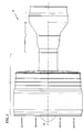
- Fig. 2A illustrates the relationship during assembly of the engine of the two main subassemblies: a first subassembly of the fan-low compressor with a fan blade 44 installed and another fan blade being installed; and, a second subassembly that comprises the rest of the engine.
- the fan rotor blades 44 are axially inserted into the fan rotor disk as one of the last steps of assembling the engine.
- Fig. 2A shows the engine during the method of assembly as discussed later with at least one fan blade 44 installed and with the next blade moving on its path of insertion.
- Each fan blade 44 has a root or dovetail 46 which engages a corresponding slot 48 in the fan rotor disk. Alternatively, the fan blade might be pinned to the rotor disk.
- the low pressure compressor also includes a drum rotor 50 which is part of the low pressure rotor assembly 24. The drum rotor is so called because of its drum-like shape. The drum rotor extends rearwardly from the fan rotor disk.
- the drum rotor has dovetail attachment members 52.
- the members adapt the rotor to receive rotor elements such as a plurality of arrays of rotor blades as represented by the rotor blades 54, 56, 58, 62, 64, and 66.
- the stator assembly 26 has an interior casing or outer case 68 which extends circumferentially about the rotor assembly.
- the outer case includes a flow path wall 69 for the bypass flowpath.
- the rotor blades extend radially outwardly across the working medium flow path 18.
- Each rotor blade has a tip, as represented by the tips 72, 74, 76, 78, 82, 84.
- An outer air seal 85 has outer air seal lands 86 which extend circumferentially about the outer case.
- the outer seal lands are disposed radially outwardly of the arrays of rotor blades to block the loss of working medium gases from the flowpath.
- These seal lands generally "rubstrips", are in close proximity to the rotor assembly 24.
- a plurality of arrays of stator vanes, as represented by the stator vanes 92, 94, 96, 98, 102 and 104 extend radially inwardly from the outer case into at least close proximity with the drum rotor.
- Each stator vane has a tip, as represented by the tip 106.
- An inner air seal 108 is disposed between the stator vanes 92-104 and the drum rotor 50.
- Each inner air seal 108 has a seal land 112 which extends circumferentially about the tips 106 of the stator vanes.
- the seal land is disposed in at least close proximity to the drum rotor.
- the drum rotor is adapted by rotor elements, as represented by the knife edge seal elements 114, which extend outwardly and cooperate with the seal land to form the inner air seal.
- the knife edge seal elements have a greater height than width and are relatively thin. The knife edge elements cut into the seal land under operative conditions as the knife edge elements move radially outwardly under operative conditions. An example of such a construction is shown in U.S.
- Patent 4,257,753 issued to Bradley et al. entitled “Gas Turbine Engine Seal and Method for Making a Gas Turbine Engine Seal.”
- the seal land in Bradley has a thin film surface layer that is resistant to erosion and provides a small amount of wear to the knife edge element. It may be formed of metallic fibers and a silicone based resin.
- seal land 112 Another type of material for the seal land 112 is an elastomeric material such as room temperature vulcanizing rubber.
- elastomeric material such as room temperature vulcanizing rubber.
- One satisfactory material for the inner air seal land is silicone rubber available as DC93-18 silicone rubber from the Dow Corning Corporation 2200 W Salzburg Rd, Auburn, Michigan 48611.
- a satisfactory material for the outer air seal land 86 (rubstrip) is available as Dow Corning 3-6891 silicone rubber available from Dow Corning Corporation, Midland, Michigan. Each silicone rubber is abradable and accepts rubbing contact with rotating structure without destruction.
- An assembly clearance and an operative clearance are provided between the rotor 24 assembly and stator assembly 26.
- Examples are the clearances between the rotor blade tips 72-84 and the outer air seal lands 86; between the knife edge elements 114 and the inner air seal land 112 of the stator vanes 92-102; and, between other locations in the engine where rubbing contact might take place between rotating parts and stationary parts in the low pressure compressor and the low pressure turbine.
- the assembly clearance provides a radial distance between the rotor elements (rotor blade, knife edge) and the stator assembly to take into account radial tolerances on the rotor disk 42 or drum rotor 50, the blades 44, 92-104, and the seal lands 86, 112.
- the assembly clearance is necessary to permit initial inspection of the assembly by turning (rotating) the assembly about the axis Ar by hand or at very slow speeds with low force. This inspection ensures that a destructive interference does not occur at some location during normal operations of the engine at high speeds. Such interference might occur between parts of the low pressure compressor 28, between parts of the low pressure turbine 30 and between the low shaft 32 that connects them and other parts of the engine.
- the clearance is helpful in assembling the fan rotor blades 44 to the fan rotor disk 42.
- the fan blades 44 are axially inserted into the rotor disk 42. These are inserted one at a time.
- the rotor disk is turned by hand, bringing the slot 48 receiving the rotor blade to a location where a worker can insert the fan rotor blade while standing in front of the engine or on a small step ladder.
- the worker must climb a taller ladder and maintain his balance while maneuvering the very heavy fan blade (sometimes weighing in excess of twenty pounds) into some of the higher oriented slots. As a result, workers will try to force the rotor to turn or request that engine be disassembled and reassembled with more clearance.
- the gap of concern is between the rotor element and the adjacent surface of the seal land before and after the rotor element.
- a gap caused by a rub of the rotor element surprisingly has a small effect on aerodynamic performance.
- a gap with respect to the adjacent structure might create a leak path between the rotor assembly 24 and the compressor, such as between the blade tips and the rubstrip and between the knife edges of the drum rotor and the adjacent seal land carried by the tips of the stator vanes.
- the gap at cruise provides an escape path for the working medium gases around the rotor blades.
- the gap at cruise is a concern because the engine may spend a significant amount of time at the cruise condition during long flights.
- the nominal clearance at assembly is set within a tolerance band (permitted variation) that trades off the need for aerodynamic efficiency against the need for an acceptable assembly clearance; one that facilitates building the rotor assembly by being able to rotate the rotor assembly 24 by hand at very low speeds during fabrication. Accordingly, the nominal clearance at assembly with its tolerance band sets a radial zone of locations for the rotor elements that avoids too tight or too large clearances.
- the nominal value of the clearance might be one-hundred and seventy two (172) mils plus or minus twenty-five mils (4.4 mm ⁇ 0.6 mm), that is, with a tolerance band from a maximum clearance dimension of one hundred and ninety seven (197) (5 mm) mils to a minimum clearance dimension of one-hundred and forty seven (147) mils (3.7 mm).
- This radial zone of rotor locations may be applied to an element rotating at over three thousand (3000) revolutions per minute at a four foot (1.21 m) diameter.
- the radial position of the tolerance band at assembly must take into account not only assembly and operative aerodynamic considerations, but also the average diameter Dav of the outer case (e.g. outer seal land 86) at a particular axial location.
- the stacking line S for the rotor blades in the assembled condition is used is the axial location at the outer air seal used for measuring the average diameter of the seal land.
- the stacking line S is the spanwise reference line on which the chordwise extending airfoil sections are disposed perpendicular to the stacking line to define the contour of the rotor blade.
- drum rotors 50 require further processing which includes an axial extending parting line or split in the outer case.
- the parting line allows the two halves (or more parts if not cut in half in a longitudinal direction) to be bolted together about the drum rotor to dispose the outer seal lands 86 and the inner seal lands 112 about the rotor elements.
- the outer case in many applications is several feet in diameter and may be as thin as one hundred and fifty (150) mils (3.8 mm) and formed of an aluminum alloy such as Aerospace Materials Specification (AMS) 4312.
- AMS Aerospace Materials Specification
- gas turbine engines are not built with too tight clearances because the rotor, such as a drum rotor 50, cannot be rotated at assembly.
- the rotor is rotated and often the tolerances are increased.
- a positive minimum clearance dimension is always provided for those rotor blades 54, 56, 58 that grow radially outwardly and rub against the rubstrip while attempting to set the nominal (average) clearance dimension to arrive at a line on line clearance (zero clearance) at the cruise condition.
- the arrays of rotor blades 62, 64, 66 in the rear of the compressor adjacent a rapidly converging flow path are different. It has been observed that one or more of these arrays of rotor blades do not tend to rub at the cruise operative condition.
- These rotor blades have a positive nominal clearance dimension with a minimum clearance dimension that is zero as measured at the stacking line; and with a maximum clearance dimension that is greater than thirty (30) mils (0.8 mm) in one application.
- the rotor blade 66 may have a tip 70 which extends rearwardly (chordwisely) at about the same angle as the rubstrip. However, it is angled slightly inwardly in the spanwise directions to provide a taper in the event of a rub. A rub, which might occur at an extreme Sea Level Take Off operative condition, would cause the tapered tip to cut a trench in the rubstrip that is tapered rearwardly with decreasing depth. This taper is provided for aerodynamic reasons. As a result, the forward most portion of the rotor blade 66 at the minimum zero tolerance dimension might have an interference fit of about one to two mils (.001-.002 inches) (0.0025-0.05 mm).
- the knife edge seal projections or elements 114 are a third category. These are provided with a minimum clearance and a nominal clearance that is smaller than the forward rotor blades 54, 56, 58 but insures that the knife edges cut a groove under operative conditions and run in the groove in the cruise operative condition on the seal land that each knife edge engages.
- This invention is in part predicated on the recognition that applying a lubricating substance at assembly to the surface of a seal land reduces the frictional force resulting from rotational contact between the rotor assembly and the stator assembly of the low pressure compressor during assembly to such an extent that the low pressure compressor may be readily turned by hand even with a zero minimum clearance in the rear stages of the compressor and does not degrade the performance of the components with which the lubricant comes in contact.
- a method of assembling a rotary machine includes applying a lubricant to the surface of a circumferentially extending seal land for the rotor assembly and stator assembly to reduce friction at assembly between the seal land and the adjacent structure as the rotor assembly is turned during assembly.
- the method includes forming a subassembly which includes the low compressor rotor assembly; forming a case assembly for the low compressor rotor assembly; and applying a lubricant to at least one seal land prior to assembling the case assembly to the rotor assembly.
- the method includes disposing the rotor assembly such that at least one rotor element has an interference fit with the seal land over a portion of the circumference of the seal land; and, rotating the rotor assembly to axially insert one fan rotor blade after another fan rotor blade into the rotor assembly.
- the method includes disposing a lubricant on an inner seal land and having an interference fit between the inner seal land and the adjacent knife edge over a portion of the circumference of the seal land which is greater than fifteen (15) mils (0.4 mm).
- the step of disposing the fan rotor blades in the rotor assembly includes applying a torque to the rotor assembly to turn the rotor assembly to bring the fan blade slot into a position convenient for inserting the fan blade, with a torque that is less than forty foot pounds force (40 ft-lbf) (54.2 Nm).
- a primary feature of the present invention is the step of disposing a lubricant on a seal land.
- the seal land is elastomeric. Another feature is allowing the lubricant to remain on the seal land for a period of time that exceeds several days. Another feature is applying a low torque to turn the rotor assembly even though at least one rotor blade or element has an interference fit with the seal land.
- a primary advantage of the present invention is the speed and efficiency with which a gas turbine engine may be assembled and which results from decreasing frictional forces between the rotor assembly and the stator assembly.
- Another advantage is the flexibility in assembling the engine which results from installing the outer case after disposing lubricant on the rotor land and then being able to delay assembling the fan blades for at least several days because the lubricant on the elastomeric seal materials does not lose the ability to reduce friction during the delay.
- Still another advantage is the structural integrity of the gas turbine engine which results form the benign interaction between the lubricant and the surface of the seal land.
- the fan portion of the low pressure compressor has a large diameter fan case 112.
- the fan case extends about the assembly of the fan rotor disk 42 and fan rotor blades 44.
- the engine 10 is disposed in a fixture for supporting the engine or suspended above the floor.
- the height of the engine above the floor at the top of the engine can be as much as ten (10) to twelve (12) feet (3-3.7 m).
- Fig. 3 shows a portion of a stator assembly and rotor assembly, as represented by the low pressure rotor assembly 24 shown in Fig.2.
- Many other types of stator and rotor assemblies might be formed, each having at least two rotor elements, such as rotor blades and knife edges and having seal lands for the rotor elements.
- the fan rotor disk 42 and the bearing 34 supporting the fan rotor disk are broken away for clarity.
- the core flowpath 18 for working medium gases has a mean flow line M in the low pressure compressor 28.
- the mean flowpath line is approximately midway between the drum rotor 50 and the interior case 68 of the engine (commonly referred to as the outer case).
- the flow path converges radially inwardly in the axial direction with a negative slope with respect to the axial direction.
- the absolute value of the negative slope is greater in the aft region of the compressor than in the mid region of the compressor.
- the rubstrips 86 adjacent the rearmost rotor blades 62, 64, 66 are angled inwardly at an angle greater than 15° toward the axis of rotation Ar and in the spanwise direction.
- the rubstrips form a frustoconical surface which extends circumferentially about the axis rotation A r of the engine.
- Fig. 4 is an exploded schematic view of the engine shown in Figures 1-3.
- the drum rotor 50 extends rearwardly from the fan rotor disk 42.
- the drum rotor has a first end 124 which is attached to the fan rotor disk to support the drum rotor from the fan rotor disk.
- the drum rotor has a second end 126 spaced rearwardly from the first end.
- the second end has a rearmost rotor disk 128 which includes a rim 132, a web 134, and a bore 136.
- the bore is spaced radially from the rim by the web.
- the drum rotor has the arrays of rotor blades 54-66.
- the arrays extend outwardly in a generally radial direction.
- radial direction includes the direction in which the rearmost blades extend which is a direction that is substantially radial.
- the stator assembly 26 has the rubstrips 86 which are disposed radially outwardly from each of the arrays of rotor blades.
- the rubstrips are formed of elastomeric material and have an average diameter Dav in the non-operative condition at the axial location that coincides with the intersection of the stacking lines of the rotor blade with the rubstrip in the non-operative condition.
- the rubstrips 86 extend rearwardly at about the same angle as the tips 70-82 of the rotor blade.
- the tips might be tapered slightly rearwardly in the spanwise direction to cut a tapered trench upon a rub.
- the stator assembly 26 includes the outer case 68.
- the outer case is formed from sections (68a, 68b, 68c, 68d, 68e, 68f) of circumferentially continuous structure. Each section is split longitudinally into at least two axially and circumferentially extending portions. As shown in Fig. 3, the axial sections are bolted together axially and circumferentially to join the halves of the outer case. The flanges on the sections coupled with the relatively large diameter and thinness of the structure cause small anomalies in the roundness (or concentricity) of the outer case. As a result, the case supports and positions the rub strips in such a way that the rubstrip is not a perfect circle at the first axial location.
- the rotor blades are formed AMS 4928 titanium alloy.
- the drum rotor 62 is also formed of a material having the same composition as AMS4928 titanium alloy but the drum rotor has been heat treated to have a slightly different material structure.
- the outer case material is formed of AMS 4312 aluminum alloy. The coefficient of thermal expansion for the outer case material is greater that the coefficient of thermal expansion for the rotor disk and rotor blades and for some material may be as much as two to three times greater than the thermal coefficient of expansion for the drum rotor and rotor blades.
- FIG. 4 is helpful in understanding the method of assembling the gas turbine engine shown in Fig.1 and Fig.2.
- a first engine subassembly is formed which is adapted to receive the outer case and will include the outer case after the outer case is installed.
- the first engine subassembly is shown oriented to receive the outer case.
- the first engine subassembly includes only part of the low compressor portion of the low pressure rotor assembly (e.g. fan rotor disk, bearing, drum rotor, and rotor blades). It does not include the fan blades and the outer case.
- a second subassembly that exists or will exist that is formed of the fan case, fan struts 123 (partially broken away), high pressure compressor, combustion section 14 and turbine section 16. These are installed later.
- the second subassembly is shown in Fig. 2 with respect to the first engine subassembly with the outer case installed and the fan blades being installed.
- the fan rotor blades are shown exploded away from fan rotor disk and axially positioned above the fan rotor disk for purposes of illustration.
- the next step is to dispose a lubricant on one of the seal lands, such as the inner seal lands 112 or on the surface of one of the outer air seal lands 86 (rubstrips) of the low pressure compressor 28.
- a lubricant is disposed on the surface of all the inner air seal lands and on the surfaces of the two rearmost, outer air seal lands that are adjacent to rotor blades 64, 66.
- the seal lands are formed of silicone rubber.
- One satisfactory lubricant is silicone oil.
- One acceptable oil is KF-54 Silicone Oil available from the Shin Etsu Company LTD Tokyo, Japan having offices at 1150 Davmar Drive, Akron, Ohio 44305. This oil was found compatible with the titanium alloy of the drum rotor, the titanium alloy of the blades, the aluminum alloy of the outer case and with the silicone rubber of the outer air seal. The viscosity of the oil is about two hundred (200) centipoise at room temperature and pressure.
- the next step is disposing the two halves of the outer case 68 about the first engine subassembly and includes joining the two halves together with bolts.
- Each of the seal lands has an average diameter Dav at the associated first axial location at the stacking line S.
- the rotor element has a tolerance band having a minimum and maximum clearance dimension about the nominal clearance dimension as measured with respect to the average diameter Dav. This defines the relative radial position of each seal land with respect to the rotor assembly. Even with a zero minimum clearance dimension or with a positive minimum clearance dimension, there will be rubbing contact over at least a portion of the circumferential travel of a rotor element 54-66, 114 because of deviations in roundness or concentricity in the seal land. Examples of rubbing contact might occur with one of the knife edge elements 114 or with one of the rotor blades such as the rearmost rotor blade 66 because of anomalies in the circumference of the case.
- the flowpath wall 69 might be part of the first engine subassembly at the time the outer case 68a-f is disposed about the rotor assembly or it may be added after disposing the two halves of the outer case about the rotor assembly.
- Joining the two subassemblies together readies the engine as shown in Fig.2 to receive the fan rotor blades. Joining the two subassemblies together does not form part of this invention. It may be done prior to the fan blades being installed or after the fan blades are installed.
- an advantage of the present invention is the flexibility in time of assembly which results from being able to accept a delay of many days prior to assembling the fan rotor blades to the fan rotor disk. It is related to the viscosity of the lubricant which keeps the lubricant distributed about the seal lands.
- the step of installing the fan blades is most easily performed by rotating the low pressure rotor assembly 24 about the axis of rotation to bring the slot of the fan rotor blade to a convenient location. This occurs by applying a torque of less than one hundred foot pounds force (100 ft-lbf) (135 Nm) to the rotor assembly.
- the clearances and anomalies in the diameter of the seal lands have made it difficult to rotate a rotor assembly that engages an unlubricated seal land. This is especially so if the land happens to have an anomaly or tolerance variation that causes a tight actual clearance.
- the fan rotor blades 44 are inserted one at a time during the step of assembling the fan rotor blades to the rotor assembly.
- the method includes rotating the low pressure rotor assembly 24 about the axis of rotation Ar by applying a torque of less than one hundred foot pounds force (100 ft-lbf) (135 Nm) to the rotor assembly. This is a marked reduction from the torque required to rotate an unlubricated assembly.
- the step is repeated time after time until all fan rotor blades are assembled to the fan rotor disk 42.
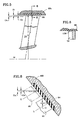
- Fig.5 is an enlarged view of one of the rotor blades and an outer seal land at the average diameter Dav of the seal land. Clearances are measured in the true radial direction perpendicular to the ideal axis of rotation Ar of the engine. For example in the field with a rotor blade, clearances are measured by direct comparison. For a rotor blade, the clearance is measured along the stacking line and is then calculated through the angle of the stacking line to the true value along a line R in the radial direction perpendicular to the ideal axis of rotation A r . The line R passes through the intersection of the stacking line S and the tip.
- the blade tip location has a tolerance applied to the rotor blade which has a nominal clearance dimension Cn, a positive minimum clearance dimension Cl, and a maximum clearance dimension Ch.
- the minimum clearance dimension Cl is positive, that is, ideally there is a clearance space or gap at the minimum clearance dimension between the blade tip and the average diameter Dav of the outer air seal land 86.
- the rotor blade will cut a groove or trench in the outer air seal land. The groove does not decrease aerodynamic performance at the cruise condition to the extent that a positive clearance decreases aerodynamic performance.
- a too tight clearance Cl or an anomaly in diameter may catch the rotor blade 54. Catching the rotor blade may cause the rotor blade to create a ridge of material 138 in the outer seal land 86 which acts as a barrier to rotational movement in the rotor blade.
- silicone oil was applied to the seal land 86 and new blades having the ten mil (0.25 mm) interference fit blades were installed. The blades did not bend and the drum rotor turned relatively easily with respect to the seal land.
- Fig. 7 is a schematic representation of movement of the drum rotor 50 shown in Fig. 3 in the static non-operative condition and the dynamic cruise operative condition.
- the static position is shown in full.
- the deflected position during rotation at cruise is shown in greatly exaggerated fashion by phantom lines.
- the drum rotor 50 deflects outwardly under the severe rotational forces that result from rotating the rotor at over three thousand revolutions per minute. This outward movement or growth causes axial (lateral) contraction related in part to axial stresses the Poisson Contraction Effect (Poisson's Ratio).
- the first end 124 of the drum rotor is fixed to the rotor disk and moves as does the massive fan rotor disk to which it is firmly attached.
- the relatively heavy dovetail attachments of the drum rotor engage the base of the rotor blades.
- the dovetail attachment members 52 move outwardly.
- the rear dovetail attachment members move forwardly as a result of the axial contraction.
- the relatively thin material of the drum rotor extending between the dovetail attachments deflects outwardly at the ends.
- the rearmost rotor disk 128 restrains the second end against radial outward movement. As a result, the second end of the drum rotor moves axially forwardly more than it moves radially outwardly, opening the clearance of the rearmost arrays of rotor blade tips with the rubstrip.
- Fig. 8 is a schematic representation of the relationship of the tip of the rearmost rotor blade to the rubstrip.
- the blade tip is shown in full and the moved position is shown by the phantom lines at the minimum clearance dimension Cl.
- the moved position of the rubstrip, which moves outwardly, is not shown.
- a minimum clearance dimension of zero at the stacking line results in a minimum clearance dimension at cruise which is positive, allowing working medium gases to escape around the tips of the rotor blades.
- the minimum clearance dimension Clc at the cruise operative condition might be still negative. If positive at the cruise condition as shown, the minimum clearance dimension Clc is still smaller than the minimum clearance dimension Clc' if the initial assembly minimum clearance dimension was zero shown by the dotted line in the moved position or, even worse, if it were a positive minimum clearance dimension not having an interference fit at assembly. This will greatly increase the efficiency of the array of rotor blades and the operational efficiency of the compressor.
- Lubricating the inner air seal lands will further reduce frictional forces at assembly. This saving in frictional force may be used to tighten nominal assembly clearances further without making it impossible to rotate the drum rotor 50. However, care must be taken that the frictional force at the rearmost seal land does not deform the rotor blade during assembly . Accordingly, it may be possible to reduce the clearance at the rearmost seal land without lubricating that particular seal land.
- Another way to decrease the friction of the inner air seal lands would be to run the engine with relatively short blades at the rearmost stage, and run in the knife edge elements to the inner air seal lands. Thereafter, the engine would be disassembled and reassembled with longer rotor blades in the rearmost disk.
- the use of the silicone oil can permit clearances that provide for a minimum clearance dimension that is negative during assembly to such an extent that the rotor blade has a minimum negative clearance across the entire tip of the rotor blade in the chordwise direction.
- the silicone rubber was checked through a fluid exposure test in which durometer readings were taken and found unchanged after periods which demonstrated the compatibility of the silicone oil with the silicone rubber.
- the silicone oil and the residue was compatible with the titanium alloy of the low pressure compressor and of the high pressure compressor.
Landscapes
- Engineering & Computer Science (AREA)
- Mechanical Engineering (AREA)
- General Engineering & Computer Science (AREA)
- Structures Of Non-Positive Displacement Pumps (AREA)
- Manufacture Of Motors, Generators (AREA)
Applications Claiming Priority (2)
| Application Number | Priority Date | Filing Date | Title |
|---|---|---|---|
| US218705 | 1998-12-22 | ||
| US09/218,705 US6148518A (en) | 1998-12-22 | 1998-12-22 | Method of assembling a rotary machine |
Publications (3)
| Publication Number | Publication Date |
|---|---|
| EP1013888A2 true EP1013888A2 (de) | 2000-06-28 |
| EP1013888A3 EP1013888A3 (de) | 2002-07-31 |
| EP1013888B1 EP1013888B1 (de) | 2005-03-02 |
Family
ID=22816151
Family Applications (1)
| Application Number | Title | Priority Date | Filing Date |
|---|---|---|---|
| EP99310395A Expired - Lifetime EP1013888B1 (de) | 1998-12-22 | 1999-12-22 | Montagemethode für eine Turbomaschine |
Country Status (7)
| Country | Link |
|---|---|
| US (1) | US6148518A (de) |
| EP (1) | EP1013888B1 (de) |
| JP (1) | JP2000186571A (de) |
| KR (1) | KR100678528B1 (de) |
| DE (1) | DE69923935T2 (de) |
| SG (1) | SG79251A1 (de) |
| TW (1) | TW386137B (de) |
Cited By (3)
| Publication number | Priority date | Publication date | Assignee | Title |
|---|---|---|---|---|
| EP1998006A3 (de) * | 2007-05-31 | 2012-05-16 | United Technologies Corporation | Haltesystem für eine Einlassleitschaufel |
| CN103195514A (zh) * | 2012-01-05 | 2013-07-10 | 通用电气公司 | 涡轮转子边缘密封件轴向固持组件 |
| CN112747037A (zh) * | 2019-10-31 | 2021-05-04 | 新疆金风科技股份有限公司 | 轴系结构、密封组件以及风力发电机组 |
Families Citing this family (23)
| Publication number | Priority date | Publication date | Assignee | Title |
|---|---|---|---|---|
| US6341419B1 (en) * | 2000-02-29 | 2002-01-29 | General Electric Company | Loop stacked rotor assembly |
| US6898547B1 (en) * | 2000-09-11 | 2005-05-24 | Axiam, Incorporated | Rotor assembly system and method |
| US7565257B2 (en) * | 2000-09-11 | 2009-07-21 | Axiam, Incorporated | System for optimal alignment of a bearing seal on a shaft of a gas turbine |
| US7765082B2 (en) * | 2000-09-11 | 2010-07-27 | Axiam, Incorporated | System for optimal alignment of a shaft of a gas turbine |
| GB2388161A (en) * | 2002-05-02 | 2003-11-05 | Rolls Royce Plc | Gas turbine engine compressor casing |
| WO2007084100A1 (en) * | 2005-12-12 | 2007-07-26 | United Technologies Corporation | Bearing-like structure to control deflections of a rotating component |
| FR2898641B1 (fr) * | 2006-03-17 | 2008-05-02 | Snecma Sa | Habillage de carter dans un turboreacteur |
| US8950069B2 (en) * | 2006-12-29 | 2015-02-10 | Rolls-Royce North American Technologies, Inc. | Integrated compressor vane casing |
| US8219353B2 (en) | 2009-01-30 | 2012-07-10 | Axiam, Inc. | Absolute diameter measurement arm |
| US9157723B2 (en) | 2009-01-30 | 2015-10-13 | Axiam, Inc. | Absolute diameter measurement arm |
| US8684669B2 (en) * | 2011-02-15 | 2014-04-01 | Siemens Energy, Inc. | Turbine tip clearance measurement |
| US8777793B2 (en) | 2011-04-27 | 2014-07-15 | United Technologies Corporation | Fan drive planetary gear system integrated carrier and torque frame |
| US9322280B2 (en) | 2011-08-12 | 2016-04-26 | United Technologies Corporation | Method of measuring turbine blade tip erosion |
| US8863491B2 (en) | 2012-01-31 | 2014-10-21 | United Technologies Corporation | Gas turbine engine shaft bearing configuration |
| US10400629B2 (en) | 2012-01-31 | 2019-09-03 | United Technologies Corporation | Gas turbine engine shaft bearing configuration |
| US9038366B2 (en) | 2012-01-31 | 2015-05-26 | United Technologies Corporation | LPC flowpath shape with gas turbine engine shaft bearing configuration |
| US20130192198A1 (en) | 2012-01-31 | 2013-08-01 | Lisa I. Brilliant | Compressor flowpath |
| US9322337B2 (en) | 2012-06-20 | 2016-04-26 | United Technologies Corporation | Aerodynamic intercompressor bleed ports |
| US9957826B2 (en) | 2014-06-09 | 2018-05-01 | United Technologies Corporation | Stiffness controlled abradeable seal system with max phase materials and methods of making same |
| US10808720B2 (en) * | 2016-06-21 | 2020-10-20 | Rolls-Royce Corporation | Axial flow compressor assembly |
| US10934943B2 (en) | 2017-04-27 | 2021-03-02 | General Electric Company | Compressor apparatus with bleed slot and supplemental flange |
| US10914318B2 (en) | 2019-01-10 | 2021-02-09 | General Electric Company | Engine casing treatment for reducing circumferentially variable distortion |
| US20250101884A1 (en) * | 2023-09-22 | 2025-03-27 | Rtx Corporation | Multi-material flowpath wall for turbine engine |
Citations (2)
| Publication number | Priority date | Publication date | Assignee | Title |
|---|---|---|---|---|
| US4199295A (en) | 1976-11-05 | 1980-04-22 | Societe Nationale D'etude Et De Construction De Moteurs D'aviation | Method and device for reducing the noise of turbo-machines |
| US4257753A (en) | 1978-01-27 | 1981-03-24 | Toyota Jidosha Kogyo Kabushiki Kaisha | Rotary fluid vane pump with means preventing axial displacement of the drive shaft |
Family Cites Families (24)
| Publication number | Priority date | Publication date | Assignee | Title |
|---|---|---|---|---|
| US3183007A (en) * | 1961-05-15 | 1965-05-11 | Tann Corp | Seal employing oil-impregnated wicking material and method of making |
| BE789908A (fr) * | 1972-02-29 | 1973-02-01 | Federal Mogul Corp | Palier pour vitesses elevees equipe d'un dispositif d'etancheite sensible a la pression de l'air |
| US4016636A (en) * | 1974-07-23 | 1977-04-12 | United Technologies Corporation | Compressor construction |
| JPS5223531A (en) * | 1975-08-18 | 1977-02-22 | Nissan Motor | Abrasionnresistant sliding member and its production method |
| US4257735A (en) * | 1978-12-15 | 1981-03-24 | General Electric Company | Gas turbine engine seal and method for making same |
| US4532054A (en) * | 1982-12-28 | 1985-07-30 | General Electric Company | Polyetherimide bearing compositions |
| US4705463A (en) * | 1983-04-21 | 1987-11-10 | The Garrett Corporation | Compressor wheel assembly for turbochargers |
| US4611464A (en) * | 1984-05-02 | 1986-09-16 | United Technologies Corporation | Rotor assembly for a gas turbine engine and method of disassembly |
| JPS61171607A (ja) * | 1985-01-24 | 1986-08-02 | Tokai Kogyo Kk | 自動車用密封構成部材 |
| US4730832A (en) * | 1985-09-13 | 1988-03-15 | Solar Turbines Incorporated | Sealed telescopic joint and method of assembly |
| US4704075A (en) * | 1986-01-24 | 1987-11-03 | Johnston Andrew E | Turbocharger water-cooled bearing housing |
| US4897021A (en) * | 1988-06-02 | 1990-01-30 | United Technologies Corporation | Stator vane asssembly for an axial flow rotary machine |
| US4826397A (en) * | 1988-06-29 | 1989-05-02 | United Technologies Corporation | Stator assembly for a gas turbine engine |
| US5006114A (en) * | 1990-04-20 | 1991-04-09 | Rogers Bobby E | Medical valve assembly |
| US5536022A (en) * | 1990-08-24 | 1996-07-16 | United Technologies Corporation | Plasma sprayed abradable seals for gas turbine engines |
| JP2970945B2 (ja) * | 1991-01-24 | 1999-11-02 | ユナイテッド テクノロジーズ コーポレイション | ガスタービンケースに対する冷却流量の制御方法 |
| US5304032A (en) * | 1991-07-22 | 1994-04-19 | Bosna Alexander A | Abradable non-metallic seal for rotating turbine engines |
| US5299910A (en) * | 1992-01-23 | 1994-04-05 | General Electric Company | Full-round compressor casing assembly in a gas turbine engine |
| US5205708A (en) * | 1992-02-07 | 1993-04-27 | General Electric Company | High pressure turbine component interference fit up |
| US5380155A (en) * | 1994-03-01 | 1995-01-10 | United Technologies Corporation | Compressor stator assembly |
| US5456327A (en) * | 1994-03-08 | 1995-10-10 | Smith International, Inc. | O-ring seal for rock bit bearings |
| JP3435945B2 (ja) * | 1995-11-02 | 2003-08-11 | エヌオーケー株式会社 | 密封装置の初期潤滑剤塗布方法 |
| US5658127A (en) * | 1996-01-26 | 1997-08-19 | Sundstrand Corporation | Seal element cooling in high speed mechanical face seals |
| US5975533A (en) * | 1996-09-13 | 1999-11-02 | Brenco, Incorporated | Labyrinth-type seal for railway car journal bearing |
-
1998
- 1998-12-22 US US09/218,705 patent/US6148518A/en not_active Expired - Lifetime
-
1999
- 1999-04-23 SG SG9901931A patent/SG79251A1/en unknown
- 1999-05-20 TW TW088108306A patent/TW386137B/zh not_active IP Right Cessation
- 1999-12-15 JP JP11355308A patent/JP2000186571A/ja active Pending
- 1999-12-17 KR KR1019990058590A patent/KR100678528B1/ko not_active Expired - Fee Related
- 1999-12-22 DE DE69923935T patent/DE69923935T2/de not_active Expired - Lifetime
- 1999-12-22 EP EP99310395A patent/EP1013888B1/de not_active Expired - Lifetime
Patent Citations (2)
| Publication number | Priority date | Publication date | Assignee | Title |
|---|---|---|---|---|
| US4199295A (en) | 1976-11-05 | 1980-04-22 | Societe Nationale D'etude Et De Construction De Moteurs D'aviation | Method and device for reducing the noise of turbo-machines |
| US4257753A (en) | 1978-01-27 | 1981-03-24 | Toyota Jidosha Kogyo Kabushiki Kaisha | Rotary fluid vane pump with means preventing axial displacement of the drive shaft |
Cited By (3)
| Publication number | Priority date | Publication date | Assignee | Title |
|---|---|---|---|---|
| EP1998006A3 (de) * | 2007-05-31 | 2012-05-16 | United Technologies Corporation | Haltesystem für eine Einlassleitschaufel |
| CN103195514A (zh) * | 2012-01-05 | 2013-07-10 | 通用电气公司 | 涡轮转子边缘密封件轴向固持组件 |
| CN112747037A (zh) * | 2019-10-31 | 2021-05-04 | 新疆金风科技股份有限公司 | 轴系结构、密封组件以及风力发电机组 |
Also Published As
| Publication number | Publication date |
|---|---|
| JP2000186571A (ja) | 2000-07-04 |
| EP1013888B1 (de) | 2005-03-02 |
| EP1013888A3 (de) | 2002-07-31 |
| DE69923935D1 (de) | 2005-04-07 |
| US6148518A (en) | 2000-11-21 |
| SG79251A1 (en) | 2001-03-20 |
| KR20000048215A (ko) | 2000-07-25 |
| TW386137B (en) | 2000-04-01 |
| KR100678528B1 (ko) | 2007-02-05 |
| DE69923935T2 (de) | 2006-04-06 |
Similar Documents
| Publication | Publication Date | Title |
|---|---|---|
| EP1013889B1 (de) | Axiale Gasturbine | |
| EP1013888B1 (de) | Montagemethode für eine Turbomaschine | |
| EP3734018B1 (de) | Dichtung für ein gasturbinentriebwerks-bauteil und zugehöriges verfahren | |
| EP0900920B1 (de) | Einteiliger Blisk einer Gasturbine | |
| EP2071139B1 (de) | Lagermontagesystem in einer Niederdruckturbine | |
| US9410439B2 (en) | CMC blade attachment shim relief | |
| EP0616113B1 (de) | Gasturbine und Verfahren zur Montage einer Dichtung in dieser Gasturbine | |
| US5791871A (en) | Turbine engine rotor assembly blade outer air seal | |
| EP3653843B1 (de) | Luftdichtungsschnittstelle mit vorwärtseingriffsmerkmalen und aktiver abstandssteuerung für eine gasturbine | |
| JPS6244120B2 (de) | ||
| EP3680520B1 (de) | Hydrostatische dichtung mit verbesserter manöverantwort | |
| EP0537922A1 (de) | Vibrationsdämpfer für Turbinenschaufelplattform | |
| EP3653842B1 (de) | Luftdichtungsschnittstelle mit hinteren eingriffsmerkmalen und aktiver spielsteuerung für einen gasturbinenmotor | |
| EP3190266B1 (de) | Gasturbine mit rotornabendichtung | |
| EP3690193B1 (de) | Dichtung und fertigungsverfahren für eine dichtungsanordnung | |
| EP0971096B1 (de) | Befestigung eines Schaufelblattes an einem Rotor | |
| US20190316485A1 (en) | Blade outer air seal cooling fin | |
| EP3708778B1 (de) | Einsätze für geschlitzten integral beschaufelten rotor | |
| GB2280478A (en) | Gas turbine sealing assemblies. | |
| CN120273791A (zh) | 用于涡轮发动机的密封组件 | |
| US11773731B2 (en) | Bathtub damper seal arrangement for gas turbine engine | |
| US11428243B2 (en) | Variable vane arrangement with vane receptacle insert(s) | |
| EP3904638B1 (de) | Rotoranordnung | |
| US12326089B2 (en) | Seal assembly for a gas turbine engine | |
| US20250354497A1 (en) | Damping system for an integrally bladed rotor |
Legal Events
| Date | Code | Title | Description |
|---|---|---|---|
| PUAI | Public reference made under article 153(3) epc to a published international application that has entered the european phase |
Free format text: ORIGINAL CODE: 0009012 |
|
| AK | Designated contracting states |
Kind code of ref document: A2 Designated state(s): AT BE CH CY DE DK ES FI FR GB GR IE IT LI LU MC NL PT SE |
|
| AX | Request for extension of the european patent |
Free format text: AL;LT;LV;MK;RO;SI |
|
| PUAL | Search report despatched |
Free format text: ORIGINAL CODE: 0009013 |
|
| AK | Designated contracting states |
Kind code of ref document: A3 Designated state(s): AT BE CH CY DE DK ES FI FR GB GR IE IT LI LU MC NL PT SE |
|
| AX | Request for extension of the european patent |
Free format text: AL;LT;LV;MK;RO;SI |
|
| RIC1 | Information provided on ipc code assigned before grant |
Free format text: 7F 01D 11/08 A, 7F 01D 25/24 B, 7F 01D 11/12 B, 7F 01D 11/00 B, 7F 01D 25/28 B |
|
| 17P | Request for examination filed |
Effective date: 20020821 |
|
| 17Q | First examination report despatched |
Effective date: 20021104 |
|
| AKX | Designation fees paid |
Designated state(s): CH DE FR GB IE LI |
|
| GRAP | Despatch of communication of intention to grant a patent |
Free format text: ORIGINAL CODE: EPIDOSNIGR1 |
|
| GRAS | Grant fee paid |
Free format text: ORIGINAL CODE: EPIDOSNIGR3 |
|
| GRAA | (expected) grant |
Free format text: ORIGINAL CODE: 0009210 |
|
| AK | Designated contracting states |
Kind code of ref document: B1 Designated state(s): CH DE FR GB IE LI |
|
| REG | Reference to a national code |
Ref country code: GB Ref legal event code: FG4D |
|
| REG | Reference to a national code |
Ref country code: CH Ref legal event code: EP |
|
| REG | Reference to a national code |
Ref country code: IE Ref legal event code: FG4D |
|
| REF | Corresponds to: |
Ref document number: 69923935 Country of ref document: DE Date of ref document: 20050407 Kind code of ref document: P |
|
| REG | Reference to a national code |
Ref country code: CH Ref legal event code: NV Representative=s name: E. BLUM & CO. PATENTANWAELTE |
|
| ET | Fr: translation filed | ||
| PLBE | No opposition filed within time limit |
Free format text: ORIGINAL CODE: 0009261 |
|
| STAA | Information on the status of an ep patent application or granted ep patent |
Free format text: STATUS: NO OPPOSITION FILED WITHIN TIME LIMIT |
|
| 26N | No opposition filed |
Effective date: 20051205 |
|
| PGFP | Annual fee paid to national office [announced via postgrant information from national office to epo] |
Ref country code: IE Payment date: 20061011 Year of fee payment: 8 |
|
| PGFP | Annual fee paid to national office [announced via postgrant information from national office to epo] |
Ref country code: CH Payment date: 20061026 Year of fee payment: 8 |
|
| REG | Reference to a national code |
Ref country code: CH Ref legal event code: PFA Owner name: UNITED TECHNOLOGIES CORPORATION Free format text: UNITED TECHNOLOGIES CORPORATION#UNITED TECHNOLOGIES BUILDING, 1 FINANCIAL PLAZA#HARTFORD, CT 06101 (US) -TRANSFER TO- UNITED TECHNOLOGIES CORPORATION#UNITED TECHNOLOGIES BUILDING, 1 FINANCIAL PLAZA#HARTFORD, CT 06101 (US) |
|
| REG | Reference to a national code |
Ref country code: CH Ref legal event code: PL |
|
| REG | Reference to a national code |
Ref country code: IE Ref legal event code: MM4A |
|
| PG25 | Lapsed in a contracting state [announced via postgrant information from national office to epo] |
Ref country code: LI Free format text: LAPSE BECAUSE OF NON-PAYMENT OF DUE FEES Effective date: 20071231 Ref country code: IE Free format text: LAPSE BECAUSE OF NON-PAYMENT OF DUE FEES Effective date: 20071224 Ref country code: CH Free format text: LAPSE BECAUSE OF NON-PAYMENT OF DUE FEES Effective date: 20071231 |
|
| PGFP | Annual fee paid to national office [announced via postgrant information from national office to epo] |
Ref country code: FR Payment date: 20081205 Year of fee payment: 10 |
|
| REG | Reference to a national code |
Ref country code: FR Ref legal event code: ST Effective date: 20100831 |
|
| PG25 | Lapsed in a contracting state [announced via postgrant information from national office to epo] |
Ref country code: FR Free format text: LAPSE BECAUSE OF NON-PAYMENT OF DUE FEES Effective date: 20091231 |
|
| REG | Reference to a national code |
Ref country code: DE Ref legal event code: R082 Ref document number: 69923935 Country of ref document: DE Representative=s name: SCHMITT-NILSON SCHRAUD WAIBEL WOHLFROM PATENTA, DE |
|
| REG | Reference to a national code |
Ref country code: DE Ref legal event code: R082 Ref document number: 69923935 Country of ref document: DE Representative=s name: SCHMITT-NILSON SCHRAUD WAIBEL WOHLFROM PATENTA, DE Ref country code: DE Ref legal event code: R081 Ref document number: 69923935 Country of ref document: DE Owner name: UNITED TECHNOLOGIES CORP. (N.D.GES.D. STAATES , US Free format text: FORMER OWNER: UNITED TECHNOLOGIES CORP., HARTFORD, CONN., US |
|
| PGFP | Annual fee paid to national office [announced via postgrant information from national office to epo] |
Ref country code: DE Payment date: 20181126 Year of fee payment: 20 |
|
| PGFP | Annual fee paid to national office [announced via postgrant information from national office to epo] |
Ref country code: GB Payment date: 20181127 Year of fee payment: 20 |
|
| REG | Reference to a national code |
Ref country code: DE Ref legal event code: R071 Ref document number: 69923935 Country of ref document: DE |
|
| REG | Reference to a national code |
Ref country code: GB Ref legal event code: PE20 Expiry date: 20191221 |
|
| PG25 | Lapsed in a contracting state [announced via postgrant information from national office to epo] |
Ref country code: GB Free format text: LAPSE BECAUSE OF EXPIRATION OF PROTECTION Effective date: 20191221 |