EP1013931A2 - Pompe de refoulement de vapeurs - Google Patents
Pompe de refoulement de vapeurs Download PDFInfo
- Publication number
- EP1013931A2 EP1013931A2 EP99123667A EP99123667A EP1013931A2 EP 1013931 A2 EP1013931 A2 EP 1013931A2 EP 99123667 A EP99123667 A EP 99123667A EP 99123667 A EP99123667 A EP 99123667A EP 1013931 A2 EP1013931 A2 EP 1013931A2
- Authority
- EP
- European Patent Office
- Prior art keywords
- valve
- shut
- temperature
- pump device
- dependent
- Prior art date
- Legal status (The legal status is an assumption and is not a legal conclusion. Google has not performed a legal analysis and makes no representation as to the accuracy of the status listed.)
- Granted
Links
Images



Classifications
-
- F—MECHANICAL ENGINEERING; LIGHTING; HEATING; WEAPONS; BLASTING
- F04—POSITIVE - DISPLACEMENT MACHINES FOR LIQUIDS; PUMPS FOR LIQUIDS OR ELASTIC FLUIDS
- F04B—POSITIVE-DISPLACEMENT MACHINES FOR LIQUIDS; PUMPS
- F04B37/00—Pumps having pertinent characteristics not provided for in, or of interest apart from, groups F04B25/00 - F04B35/00
- F04B37/10—Pumps having pertinent characteristics not provided for in, or of interest apart from, groups F04B25/00 - F04B35/00 for special use
- F04B37/18—Pumps having pertinent characteristics not provided for in, or of interest apart from, groups F04B25/00 - F04B35/00 for special use for specific elastic fluids
-
- F—MECHANICAL ENGINEERING; LIGHTING; HEATING; WEAPONS; BLASTING
- F04—POSITIVE - DISPLACEMENT MACHINES FOR LIQUIDS; PUMPS FOR LIQUIDS OR ELASTIC FLUIDS
- F04B—POSITIVE-DISPLACEMENT MACHINES FOR LIQUIDS; PUMPS
- F04B37/00—Pumps having pertinent characteristics not provided for in, or of interest apart from, groups F04B25/00 - F04B35/00
- F04B37/10—Pumps having pertinent characteristics not provided for in, or of interest apart from, groups F04B25/00 - F04B35/00 for special use
- F04B37/18—Pumps having pertinent characteristics not provided for in, or of interest apart from, groups F04B25/00 - F04B35/00 for special use for specific elastic fluids
- F04B37/20—Pumps having pertinent characteristics not provided for in, or of interest apart from, groups F04B25/00 - F04B35/00 for special use for specific elastic fluids for wet gases, e.g. wet air
-
- F—MECHANICAL ENGINEERING; LIGHTING; HEATING; WEAPONS; BLASTING
- F04—POSITIVE - DISPLACEMENT MACHINES FOR LIQUIDS; PUMPS FOR LIQUIDS OR ELASTIC FLUIDS
- F04B—POSITIVE-DISPLACEMENT MACHINES FOR LIQUIDS; PUMPS
- F04B49/00—Control, e.g. of pump delivery, or pump pressure of, or safety measures for, machines, pumps, or pumping installations, not otherwise provided for, or of interest apart from, groups F04B1/00 - F04B47/00
- F04B49/22—Control, e.g. of pump delivery, or pump pressure of, or safety measures for, machines, pumps, or pumping installations, not otherwise provided for, or of interest apart from, groups F04B1/00 - F04B47/00 by means of valves
-
- F—MECHANICAL ENGINEERING; LIGHTING; HEATING; WEAPONS; BLASTING
- F04—POSITIVE - DISPLACEMENT MACHINES FOR LIQUIDS; PUMPS FOR LIQUIDS OR ELASTIC FLUIDS
- F04B—POSITIVE-DISPLACEMENT MACHINES FOR LIQUIDS; PUMPS
- F04B2205/00—Fluid parameters
- F04B2205/10—Inlet temperature
Definitions
- the invention relates to a pumping device for conveying of vapors, especially vapors of low-boiling liquids according to the preamble of claim 1.
- Such pumping devices are e.g. on petrol pumps used to remove fuel from motor vehicles the motor vehicle tank displaced gasoline vapors in the Promote gas station tank.
- a pump device is therefore intended by the present invention for conveying vapors according to the generic term of claim 1 are further developed so that operational safety the pumping device, even when the Compression heat is retained.
- the temperature-dependent shut-off valve ensures for the fact that gasoline vapors only below a predetermined Temperature are promoted and thus compression heat arises. If the specified temperature is exceeded, closes the shut-off valve and the pump unit works against a standing gasoline vapor column, then no compression heat the pump device additionally can heat up since no compression work is done becomes.
- the control that closes or opens the controls the temperature-dependent shut-off valve can itself according to claim 2 by the action of heat be deformable.
- Such a control element thus serves at the same time as a temperature probe.
- control element according to claim 3 work together in a temperature-dependent deformable body. Such a structure allows use of standard shut-off valves.
- a bimetallic body i.e. a body that acts as a layer composite two metal layers with different coefficients of thermal expansion is carried out
- the bimetal body are used in different temperature ranges and with different Temperature stroke available.
- a switching characteristic of the shut-off valve i.e. also the total is still slightly below the switching temperature or a large part of the delivery capacity of the pumping device available.
- a snap action of the bimetallic body is claimed 7 particularly easy to implement.
- an expansion element can also be used.
- it is a body with a high coefficient of expansion, its thermal expansion either directly to open or close the shut-off valve or indirectly for actuating the control element of the shut-off valve is being used.
- Wax cartridge is in different geometries available, easy to use and has a high Coefficient of thermal expansion.
- control of the shut-off valve provided by a temperature sensor.
- the control of the shut-off valve is then not carried out directly or indirectly mechanically, but via a control signal of the temperature sensor.
- Such sensor valve units are relatively inexpensive.
- the additional use of the Temperature sensor for one of the shut-off valve variants mentioned above with a deformable depending on the temperature Body results in a particularly reliable pumping device.
- An electromagnet is a particularly robust and inexpensive Actuator (cf. claim 10).
- the development according to claim 11 has the character of Shutoff valve as a safety device bill. Because the shut-off valve during normal operation of the pumping device is always open, this open position is open simple way and without constant electrical control causes so that the electromagnet is protected and energy is saved.
- a gas pump to a tank 12 has a piston pump 14 Conveying gasoline vapors.
- Their inlet valve 16 and Exhaust valve 18 is outsourced for purposes of illustration shown.
- the pump device 10 pumps gasoline vapors, those when refueling a vehicle from its tank 20 be displaced using a proboscis Nozzle and a gasoline vapor return line 22, 24 back to tank 12.
- the pump device 10 also points in the conveying direction the gasoline vapors lying in front of the inlet valve 16 shut-off valve 26 operating in a temperature-dependent manner. This is thermally coupled to the piston pump 14, i.e. Shut-off valve 26 and piston pump 14 have the same Temperature. This is usually temperature-dependent working shut-off valve 26 open. The temperature rises the piston pump 14 above a predetermined limit value, the thermally coupled shut-off valve 26 closes, as will be described in more detail below.
- a pressure relief valve 28 open.
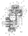
- the piston pump shown in section in Figure 2 14 has a crankcase located under operating conditions 30 and one screwed on top of it Cylinder head 32.
- a molded bearing seat 34 of the crankcase 30 is a via a bearing 36 Drive shaft 38 mounted.
- the drive shaft 38 is about an electric motor, not shown in the drawing, the left in Figure 2 of the bearing holder 34 outside of Crankcase 30 is arranged, driven.
- With the Drive shaft 38 is a crank body via a threaded bolt 40 42 connected to which a balancing body 44 is integrally formed is.
- Runs on a crank pin 46 of the crank body 42 via a bearing 48 a connecting rod 50 on which a lower Piston shell 52 is integrally formed.
- a piston seal is located between the two piston shells 52, 54 58 trapped.
- the piston unit formed by the components 50 to 58 60 runs in a cylinder liner 62, which has two axially successive disc springs 64 on one shoulder 66 of the crankcase 30 rests and on the underside of the cylinder head 32 via a valve support plate 68 is supported.
- the latter bears the leaf spring Inlet valve 16, not shown in Figure 2 designed as a leaf spring outlet valve 18, the temperature dependent working shut-off valve 26 and the pressure relief valve 28
- the shut-off valve 26 has a conical bowl-shaped Snap valve disk 70 made of bimetal with a central one Hole 72 (see. In particular Fig. 3 and 4) with which it on a threaded bolt 74 of the valve support plate 68 is stuck.
- a nut 76 is on the threaded bolt 74 screwed, the valve plate 70 against one on the Valve carrier plate 68 adjacent spacer ring 78, the is also plugged onto the threaded bolt 74.
- An upper flat sealing surface 80 of the valve carrier plate 68 forms with an outer edge 82 of the valve plate 70 a linear circular sealing point if the Valve plate 70 under the action of heat in a down conical shell-shaped closing geometry is snapped.
- the circular sealing point lies radially outside of one formed in the valve support plate 68 inlet opening 84, with the lower end of the inlet valve 16 cooperates.
- the pressure relief valve 28 is on the outlet side with the inlet 88 of the crankcase with a suction space 86 and on the inlet side with an outlet 90 of the piston pump 14 in connection.
- the Pressure relief valve 28 are in the flow direction of the gasoline vapor the temperature-dependent shut-off valve 26, the inlet valve 16 and the outlet valve 18 downstream.
- An outlet 90 of the piston pump 14 is via the Line 24 (see FIG. 1) connected to the tank 12.
- flame retardants 92 and 94 are flame retardants 92 and 94, respectively intended.
- the latter each have a winding 96 made of corrugated Sheet metal tape (tape securing).
- the switching temperature If the switching temperature is exceeded, it snaps the valve plate 70 of the shut-off valve 26 via a unstable middle position in the closed position shown in FIG. 4, at which the edge 82 of the valve plate 70 the sealing surface 80 of the valve carrier plate 68 rests, so that the inlet opening 84 is closed and the Piston unit 60 regardless of the position of the intake valve 16 and outlet valve 18 to one and the same gas volume is working. The conveyance of gasoline vapor through the Piston pump 14 is thus prevented.
- the piston pump 14 thus operates in the closed position of the shut-off valve 26 against one in the area of the outlet 90 standing gasoline vapor column, which no further is compressed and therefore does not heat up. Vice versa the piston pump 14 continues by convection cooled by ambient air. This cooling is stronger than the frictional heat still generated in the piston pump 14, so that a total cooling of the pumping device 10 receives.
- Valve plate 70 of the shut-off valve 26 After clearly falling below the switching temperature (Hysteresis of the bimetal valve disc) snaps Valve plate 70 of the shut-off valve 26 again in the Inlet opening 84 releasing open position, whereby the Piston unit 60 can suck gasoline vapor again.
- the temperature-dependent one shown in FIG Shut-off valve 26 is controlled by a piston 102 that runs tightly in a cylindrical housing 104, in which an expansion element 106 is arranged.
- the Expansion element 106 e.g. a wax cartridge, stretches out with increasing temperature.
- the stroke of the piston 102 is dimensioned so that the shut-off valve 26 then opens, when an expansion of the expansion element 106 reaches which corresponds to the switching temperature.
- the piston 102 is under the bias of a spring 108, so when Contraction of the expansion element 106 of the pistons 102 is tracked in contact with the expansion element 106, and the shut-off valve 26 when the switching temperature falls below opens again.
- the temperature-dependent one shown in FIG. 6 Shut-off valve 26 is resiliently biased into the open position and via an electromagnet 110 in the closed position adjustable.
- the electromagnet 110 is one Temperature switch 112 controlled, the thermally to the Piston pump 14 is coupled. When exceeding the The temperature switch 112 excites the switching temperature a power amplifier 114 the electromagnet 110, so that it closes the shut-off valve 26. When falling short the temperature switch ends the switching temperature 112 its output signal, so that the shut-off valve 26 is opened again.
Landscapes
- Engineering & Computer Science (AREA)
- Mechanical Engineering (AREA)
- General Engineering & Computer Science (AREA)
- Reciprocating Pumps (AREA)
- Temperature-Responsive Valves (AREA)
- Air Transport Of Granular Materials (AREA)
- Jet Pumps And Other Pumps (AREA)
- Structures Of Non-Positive Displacement Pumps (AREA)
- Control Of Non-Positive-Displacement Pumps (AREA)
Applications Claiming Priority (2)
| Application Number | Priority Date | Filing Date | Title |
|---|---|---|---|
| DE19859752A DE19859752A1 (de) | 1998-12-23 | 1998-12-23 | Pumpeinrichtung zum Fördern von Dämpfen |
| DE19859752 | 1998-12-23 |
Publications (3)
| Publication Number | Publication Date |
|---|---|
| EP1013931A2 true EP1013931A2 (fr) | 2000-06-28 |
| EP1013931A3 EP1013931A3 (fr) | 2000-12-13 |
| EP1013931B1 EP1013931B1 (fr) | 2006-02-01 |
Family
ID=7892458
Family Applications (1)
| Application Number | Title | Priority Date | Filing Date |
|---|---|---|---|
| EP99123667A Expired - Lifetime EP1013931B1 (fr) | 1998-12-23 | 1999-11-29 | Pompe de refoulement de vapeurs |
Country Status (4)
| Country | Link |
|---|---|
| EP (1) | EP1013931B1 (fr) |
| AT (1) | ATE317064T1 (fr) |
| DE (2) | DE19859752A1 (fr) |
| ES (1) | ES2257005T3 (fr) |
Families Citing this family (3)
| Publication number | Priority date | Publication date | Assignee | Title |
|---|---|---|---|---|
| DE102007014918A1 (de) * | 2007-03-26 | 2008-10-02 | Dürr GmbH & Co. KG Luft- und Prozessortechnik | Benzindampfpumpe |
| RU2487269C2 (ru) * | 2011-03-23 | 2013-07-10 | Федеральное государственное военное образовательное учреждение высшего профессионального образования "Военный авиационный инженерный университет" (г. Воронеж) Министерства обороны Российской Федерации | Компрессор поршневой для взрывоопасных газов |
| DE102023203130A1 (de) * | 2023-04-04 | 2024-10-10 | Volkswagen Aktiengesellschaft | Batteriezellenanordnung mit mindestens zwei Batteriezellen, insbesondere für ein Fahrzeug |
Family Cites Families (7)
| Publication number | Priority date | Publication date | Assignee | Title |
|---|---|---|---|---|
| DE1943936A1 (de) * | 1969-08-29 | 1971-03-18 | Danfoss As | Schutzanordnung fuer einen Verdichter |
| GB1527990A (en) * | 1975-12-24 | 1978-10-11 | Mitsubishi Heavy Ind Ltd | Method for recovering a vapour |
| JPS57126590A (en) * | 1981-01-29 | 1982-08-06 | Matsushita Electric Ind Co Ltd | Compressor |
| US4830277A (en) * | 1988-04-20 | 1989-05-16 | Demaich Industries, Inc. | Thermostatic valve |
| DE4239580C2 (de) * | 1992-11-25 | 1996-07-25 | Samson Ag | Stellantrieb mit Sicherheitseinrichtung |
| US5263643A (en) * | 1992-12-24 | 1993-11-23 | Therm-O-Disc, Incorporated | Thermally responsive relief valve |
| US5571310A (en) * | 1995-05-12 | 1996-11-05 | Gilbarco Inc. | Volatile organic chemical tank ullage pressure reduction |
-
1998
- 1998-12-23 DE DE19859752A patent/DE19859752A1/de not_active Ceased
-
1999
- 1999-11-29 DE DE59913096T patent/DE59913096D1/de not_active Expired - Lifetime
- 1999-11-29 AT AT99123667T patent/ATE317064T1/de not_active IP Right Cessation
- 1999-11-29 EP EP99123667A patent/EP1013931B1/fr not_active Expired - Lifetime
- 1999-11-29 ES ES99123667T patent/ES2257005T3/es not_active Expired - Lifetime
Also Published As
| Publication number | Publication date |
|---|---|
| DE19859752A1 (de) | 2000-08-10 |
| EP1013931A3 (fr) | 2000-12-13 |
| EP1013931B1 (fr) | 2006-02-01 |
| ATE317064T1 (de) | 2006-02-15 |
| DE59913096D1 (de) | 2006-04-13 |
| ES2257005T3 (es) | 2006-07-16 |
Similar Documents
| Publication | Publication Date | Title |
|---|---|---|
| EP1711698B1 (fr) | Ensemble soupape thermostatique | |
| DE2804557C3 (de) | Flüssigkeitsreibungskupplung, insbesondere für ein Kühlgebläse einer Brennkraftmaschine | |
| DE60020731T2 (de) | Kraftstoffrückführventil mit entlüftung | |
| EP2029884B1 (fr) | Pompe a jet aspirant | |
| DE19846601A1 (de) | Sammel- und Druckentlastungsmodul für eine Kraftstoffzuführanlage | |
| DE3504653A1 (de) | Thermostatventil zur regelung der temperatur der kuehlfluessigkeit einer brennkrafmaschine | |
| DE2155681A1 (de) | Vorrichtung zur Betriebssicherung des Drosselklappen-Steuermechanismus für Vergaser von Brennkraftmaschinen | |
| DE2405463C2 (de) | Vorrichtung zur Steuerung des einer Brennkraftmaschine zugeführten Kraftstoffes | |
| DE102010027655A1 (de) | Kraftstofffilter mit integrierter Temperaturregelung | |
| EP0484624B1 (fr) | Soupape thermostatique pour la régulation de la température du liquide de refroidissement d'un moteur à combustion interne | |
| EP1413809A1 (fr) | Dispositiff pour compenser l'expansion volumétrique d'un milieu | |
| DE2903561C2 (de) | Vorrichtung zum zeitverzögerten Betätigen eines Ventils oder Schalters | |
| EP1013931A2 (fr) | Pompe de refoulement de vapeurs | |
| EP3728917A1 (fr) | Soupape | |
| EP2406498A1 (fr) | Pompe de liquide de refroidissement à régulation | |
| WO2000071872A1 (fr) | Bouchon pour radiateur de vehicule automobile | |
| DE4020953A1 (de) | Stellantrieb | |
| DE4416554A1 (de) | Thermostatventil | |
| EP1113164A2 (fr) | Filtre pour le système d'alimentation en carburant d'un moteur à combustion d'un véhicule | |
| EP0821166A2 (fr) | Dispositif de sécurité pour une pompe | |
| DE3502566C2 (de) | Motorisch angetriebener Rasenmäher | |
| EP1631741B1 (fr) | Dispositif pour regler une section d'ecoulement variable | |
| EP1761706B1 (fr) | Pompe | |
| DE102012202226A1 (de) | Kraftstoffpumpanordnung für ein Kraftfahrzeug | |
| DE102005059418A1 (de) | Einrichtung zur Steuerung eines Wärmeflusses |
Legal Events
| Date | Code | Title | Description |
|---|---|---|---|
| PUAI | Public reference made under article 153(3) epc to a published international application that has entered the european phase |
Free format text: ORIGINAL CODE: 0009012 |
|
| AK | Designated contracting states |
Kind code of ref document: A2 Designated state(s): AT BE CH CY DE DK ES FI FR GB GR IE IT LI LU MC NL PT SE |
|
| AX | Request for extension of the european patent |
Free format text: AL;LT;LV;MK;RO;SI |
|
| PUAL | Search report despatched |
Free format text: ORIGINAL CODE: 0009013 |
|
| AK | Designated contracting states |
Kind code of ref document: A3 Designated state(s): AT BE CH CY DE DK ES FI FR GB GR IE IT LI LU MC NL PT SE |
|
| AX | Request for extension of the european patent |
Free format text: AL;LT;LV;MK;RO;SI |
|
| 17P | Request for examination filed |
Effective date: 20010609 |
|
| AKX | Designation fees paid |
Free format text: AT BE CH CY DE DK ES FI FR GB GR IE IT LI LU MC NL PT SE |
|
| 17Q | First examination report despatched |
Effective date: 20040709 |
|
| GRAP | Despatch of communication of intention to grant a patent |
Free format text: ORIGINAL CODE: EPIDOSNIGR1 |
|
| GRAS | Grant fee paid |
Free format text: ORIGINAL CODE: EPIDOSNIGR3 |
|
| GRAA | (expected) grant |
Free format text: ORIGINAL CODE: 0009210 |
|
| AK | Designated contracting states |
Kind code of ref document: B1 Designated state(s): AT BE CH CY DE DK ES FI FR GB GR IE IT LI LU MC NL PT SE |
|
| PG25 | Lapsed in a contracting state [announced via postgrant information from national office to epo] |
Ref country code: NL Free format text: LAPSE BECAUSE OF FAILURE TO SUBMIT A TRANSLATION OF THE DESCRIPTION OR TO PAY THE FEE WITHIN THE PRESCRIBED TIME-LIMIT Effective date: 20060201 Ref country code: IT Free format text: LAPSE BECAUSE OF FAILURE TO SUBMIT A TRANSLATION OF THE DESCRIPTION OR TO PAY THE FEE WITHIN THE PRE;WARNING: LAPSES OF ITALIAN PATENTS WITH EFFECTIVE DATE BEFORE 2007 MAY HAVE OCCURRED AT ANY TIME BEFORE 2007. THE CORRECT EFFECTIVE DATE MAY BE DIFFERENT FROM THE ONE RECORDED.SCRIBED TIME-LIMIT Effective date: 20060201 Ref country code: IE Free format text: LAPSE BECAUSE OF FAILURE TO SUBMIT A TRANSLATION OF THE DESCRIPTION OR TO PAY THE FEE WITHIN THE PRESCRIBED TIME-LIMIT Effective date: 20060201 Ref country code: FI Free format text: LAPSE BECAUSE OF FAILURE TO SUBMIT A TRANSLATION OF THE DESCRIPTION OR TO PAY THE FEE WITHIN THE PRESCRIBED TIME-LIMIT Effective date: 20060201 |
|
| REG | Reference to a national code |
Ref country code: GB Ref legal event code: FG4D Free format text: NOT ENGLISH |
|
| REG | Reference to a national code |
Ref country code: CH Ref legal event code: EP |
|
| GBT | Gb: translation of ep patent filed (gb section 77(6)(a)/1977) |
Effective date: 20060201 |
|
| REG | Reference to a national code |
Ref country code: IE Ref legal event code: FG4D Free format text: LANGUAGE OF EP DOCUMENT: GERMAN |
|
| REF | Corresponds to: |
Ref document number: 59913096 Country of ref document: DE Date of ref document: 20060413 Kind code of ref document: P |
|
| PG25 | Lapsed in a contracting state [announced via postgrant information from national office to epo] |
Ref country code: SE Free format text: LAPSE BECAUSE OF FAILURE TO SUBMIT A TRANSLATION OF THE DESCRIPTION OR TO PAY THE FEE WITHIN THE PRESCRIBED TIME-LIMIT Effective date: 20060501 Ref country code: DK Free format text: LAPSE BECAUSE OF FAILURE TO SUBMIT A TRANSLATION OF THE DESCRIPTION OR TO PAY THE FEE WITHIN THE PRESCRIBED TIME-LIMIT Effective date: 20060501 |
|
| NLV1 | Nl: lapsed or annulled due to failure to fulfill the requirements of art. 29p and 29m of the patents act | ||
| PG25 | Lapsed in a contracting state [announced via postgrant information from national office to epo] |
Ref country code: PT Free format text: LAPSE BECAUSE OF FAILURE TO SUBMIT A TRANSLATION OF THE DESCRIPTION OR TO PAY THE FEE WITHIN THE PRESCRIBED TIME-LIMIT Effective date: 20060703 |
|
| REG | Reference to a national code |
Ref country code: ES Ref legal event code: FG2A Ref document number: 2257005 Country of ref document: ES Kind code of ref document: T3 |
|
| REG | Reference to a national code |
Ref country code: IE Ref legal event code: FD4D |
|
| ET | Fr: translation filed | ||
| PG25 | Lapsed in a contracting state [announced via postgrant information from national office to epo] |
Ref country code: MC Free format text: LAPSE BECAUSE OF NON-PAYMENT OF DUE FEES Effective date: 20061130 Ref country code: LI Free format text: LAPSE BECAUSE OF NON-PAYMENT OF DUE FEES Effective date: 20061130 Ref country code: CH Free format text: LAPSE BECAUSE OF NON-PAYMENT OF DUE FEES Effective date: 20061130 Ref country code: BE Free format text: LAPSE BECAUSE OF NON-PAYMENT OF DUE FEES Effective date: 20061130 |
|
| PLBE | No opposition filed within time limit |
Free format text: ORIGINAL CODE: 0009261 |
|
| STAA | Information on the status of an ep patent application or granted ep patent |
Free format text: STATUS: NO OPPOSITION FILED WITHIN TIME LIMIT |
|
| 26N | No opposition filed |
Effective date: 20061103 |
|
| REG | Reference to a national code |
Ref country code: CH Ref legal event code: PL |
|
| BERE | Be: lapsed |
Owner name: DURR DENTAL G.M.B.H. & CO. KG Effective date: 20061130 |
|
| PG25 | Lapsed in a contracting state [announced via postgrant information from national office to epo] |
Ref country code: AT Free format text: LAPSE BECAUSE OF NON-PAYMENT OF DUE FEES Effective date: 20061129 |
|
| PG25 | Lapsed in a contracting state [announced via postgrant information from national office to epo] |
Ref country code: GR Free format text: LAPSE BECAUSE OF FAILURE TO SUBMIT A TRANSLATION OF THE DESCRIPTION OR TO PAY THE FEE WITHIN THE PRESCRIBED TIME-LIMIT Effective date: 20060502 |
|
| REG | Reference to a national code |
Ref country code: FR Ref legal event code: TP |
|
| PG25 | Lapsed in a contracting state [announced via postgrant information from national office to epo] |
Ref country code: LU Free format text: LAPSE BECAUSE OF NON-PAYMENT OF DUE FEES Effective date: 20061129 |
|
| PG25 | Lapsed in a contracting state [announced via postgrant information from national office to epo] |
Ref country code: CY Free format text: LAPSE BECAUSE OF FAILURE TO SUBMIT A TRANSLATION OF THE DESCRIPTION OR TO PAY THE FEE WITHIN THE PRESCRIBED TIME-LIMIT Effective date: 20060201 |
|
| REG | Reference to a national code |
Ref country code: ES Ref legal event code: PC2A Owner name: DURR TECHNIK GMBH & CO. KG Effective date: 20130227 |
|
| PGFP | Annual fee paid to national office [announced via postgrant information from national office to epo] |
Ref country code: ES Payment date: 20131121 Year of fee payment: 15 Ref country code: IT Payment date: 20131127 Year of fee payment: 15 |
|
| REG | Reference to a national code |
Ref country code: FR Ref legal event code: PLFP Year of fee payment: 17 |
|
| REG | Reference to a national code |
Ref country code: ES Ref legal event code: FD2A Effective date: 20151229 |
|
| PG25 | Lapsed in a contracting state [announced via postgrant information from national office to epo] |
Ref country code: IT Free format text: LAPSE BECAUSE OF NON-PAYMENT OF DUE FEES Effective date: 20141129 |
|
| PG25 | Lapsed in a contracting state [announced via postgrant information from national office to epo] |
Ref country code: ES Free format text: LAPSE BECAUSE OF NON-PAYMENT OF DUE FEES Effective date: 20141130 |
|
| REG | Reference to a national code |
Ref country code: FR Ref legal event code: PLFP Year of fee payment: 18 |
|
| REG | Reference to a national code |
Ref country code: FR Ref legal event code: PLFP Year of fee payment: 19 |
|
| PGFP | Annual fee paid to national office [announced via postgrant information from national office to epo] |
Ref country code: DE Payment date: 20181120 Year of fee payment: 20 |
|
| PGFP | Annual fee paid to national office [announced via postgrant information from national office to epo] |
Ref country code: FR Payment date: 20181123 Year of fee payment: 20 Ref country code: GB Payment date: 20181120 Year of fee payment: 20 |
|
| REG | Reference to a national code |
Ref country code: DE Ref legal event code: R071 Ref document number: 59913096 Country of ref document: DE |
|
| REG | Reference to a national code |
Ref country code: GB Ref legal event code: PE20 Expiry date: 20191128 |
|
| PG25 | Lapsed in a contracting state [announced via postgrant information from national office to epo] |
Ref country code: GB Free format text: LAPSE BECAUSE OF EXPIRATION OF PROTECTION Effective date: 20191128 |