EP1013986B1 - Robinetterie de bouteille à gaz - Google Patents
Robinetterie de bouteille à gaz Download PDFInfo
- Publication number
- EP1013986B1 EP1013986B1 EP99125257A EP99125257A EP1013986B1 EP 1013986 B1 EP1013986 B1 EP 1013986B1 EP 99125257 A EP99125257 A EP 99125257A EP 99125257 A EP99125257 A EP 99125257A EP 1013986 B1 EP1013986 B1 EP 1013986B1
- Authority
- EP
- European Patent Office
- Prior art keywords
- gas
- cylinder
- pressure
- bottle
- protective cap
- Prior art date
- Legal status (The legal status is an assumption and is not a legal conclusion. Google has not performed a legal analysis and makes no representation as to the accuracy of the status listed.)
- Expired - Lifetime
Links
- 230000001681 protective effect Effects 0.000 claims description 30
- 239000003638 chemical reducing agent Substances 0.000 abstract description 12
- 239000007789 gas Substances 0.000 description 76
- 238000000605 extraction Methods 0.000 description 4
- 230000003014 reinforcing effect Effects 0.000 description 4
- 238000004519 manufacturing process Methods 0.000 description 3
- 238000001746 injection moulding Methods 0.000 description 2
- 238000003466 welding Methods 0.000 description 2
- HSFWRNGVRCDJHI-UHFFFAOYSA-N alpha-acetylene Natural products C#C HSFWRNGVRCDJHI-UHFFFAOYSA-N 0.000 description 1
- QVGXLLKOCUKJST-UHFFFAOYSA-N atomic oxygen Chemical compound [O] QVGXLLKOCUKJST-UHFFFAOYSA-N 0.000 description 1
- 230000009286 beneficial effect Effects 0.000 description 1
- 125000002534 ethynyl group Chemical group [H]C#C* 0.000 description 1
- 239000000945 filler Substances 0.000 description 1
- 238000009434 installation Methods 0.000 description 1
- 230000010354 integration Effects 0.000 description 1
- 239000001301 oxygen Substances 0.000 description 1
- 229910052760 oxygen Inorganic materials 0.000 description 1
- 230000036316 preload Effects 0.000 description 1
- 230000001105 regulatory effect Effects 0.000 description 1
- 238000005070 sampling Methods 0.000 description 1
- 239000000243 solution Substances 0.000 description 1
Images




Classifications
-
- F—MECHANICAL ENGINEERING; LIGHTING; HEATING; WEAPONS; BLASTING
- F17—STORING OR DISTRIBUTING GASES OR LIQUIDS
- F17C—VESSELS FOR CONTAINING OR STORING COMPRESSED, LIQUEFIED OR SOLIDIFIED GASES; FIXED-CAPACITY GAS-HOLDERS; FILLING VESSELS WITH, OR DISCHARGING FROM VESSELS, COMPRESSED, LIQUEFIED, OR SOLIDIFIED GASES
- F17C13/00—Details of vessels or of the filling or discharging of vessels
- F17C13/04—Arrangement or mounting of valves
-
- G—PHYSICS
- G05—CONTROLLING; REGULATING
- G05D—SYSTEMS FOR CONTROLLING OR REGULATING NON-ELECTRIC VARIABLES
- G05D16/00—Control of fluid pressure
- G05D16/04—Control of fluid pressure without auxiliary power
- G05D16/0402—Control of fluid pressure without auxiliary power with two or more controllers mounted in series
-
- G—PHYSICS
- G05—CONTROLLING; REGULATING
- G05D—SYSTEMS FOR CONTROLLING OR REGULATING NON-ELECTRIC VARIABLES
- G05D16/00—Control of fluid pressure
- G05D16/04—Control of fluid pressure without auxiliary power
- G05D16/06—Control of fluid pressure without auxiliary power the sensing element being a flexible membrane, yielding to pressure, e.g. diaphragm, bellows, capsule
- G05D16/063—Control of fluid pressure without auxiliary power the sensing element being a flexible membrane, yielding to pressure, e.g. diaphragm, bellows, capsule the sensing element being a membrane
- G05D16/0644—Control of fluid pressure without auxiliary power the sensing element being a flexible membrane, yielding to pressure, e.g. diaphragm, bellows, capsule the sensing element being a membrane the membrane acting directly on the obturator
- G05D16/0663—Control of fluid pressure without auxiliary power the sensing element being a flexible membrane, yielding to pressure, e.g. diaphragm, bellows, capsule the sensing element being a membrane the membrane acting directly on the obturator using a spring-loaded membrane with a spring-loaded slideable obturator
-
- F—MECHANICAL ENGINEERING; LIGHTING; HEATING; WEAPONS; BLASTING
- F17—STORING OR DISTRIBUTING GASES OR LIQUIDS
- F17C—VESSELS FOR CONTAINING OR STORING COMPRESSED, LIQUEFIED OR SOLIDIFIED GASES; FIXED-CAPACITY GAS-HOLDERS; FILLING VESSELS WITH, OR DISCHARGING FROM VESSELS, COMPRESSED, LIQUEFIED, OR SOLIDIFIED GASES
- F17C2205/00—Vessel construction, in particular mounting arrangements, attachments or identifications means
- F17C2205/03—Fluid connections, filters, valves, closure means or other attachments
- F17C2205/0302—Fittings, valves, filters, or components in connection with the gas storage device
- F17C2205/0308—Protective caps
-
- F—MECHANICAL ENGINEERING; LIGHTING; HEATING; WEAPONS; BLASTING
- F17—STORING OR DISTRIBUTING GASES OR LIQUIDS
- F17C—VESSELS FOR CONTAINING OR STORING COMPRESSED, LIQUEFIED OR SOLIDIFIED GASES; FIXED-CAPACITY GAS-HOLDERS; FILLING VESSELS WITH, OR DISCHARGING FROM VESSELS, COMPRESSED, LIQUEFIED, OR SOLIDIFIED GASES
- F17C2227/00—Transfer of fluids, i.e. method or means for transferring the fluid; Heat exchange with the fluid
- F17C2227/04—Methods for emptying or filling
- F17C2227/048—Methods for emptying or filling by maintaining residual pressure
Definitions
- the invention relates to a gas cylinder fitting with provided for the user control and display elements comprising at least one actuator for a bottle closure device, a knob for a pressure reducer and a gas extraction port, all provided for the user controls and indicators are arranged within a cylindrical sector, and a gas cylinder with such a fitting.
- a compact gas bottle fitting comprising a bottle closure device, a pressure reducer and manometer known.
- the entire fitting is surrounded by a protective cover having a plurality of access openings, so that the various controls accessible and the display elements, such as the pressure displays, are readable.
- the gas cylinder is thus always protected against damage and yet ready for immediate use.
- the connecting piece for the gas sampling, the pressure gauge and the Regulierknopf for the pressure reducer however, arranged for reasons of space each offset by 90 °.
- This configuration has the disadvantage that the user of the gas cylinder can not view or operate all the operating and display elements from one position. In particular, when the gas cylinder is in a pallet or in a row with one or more other bottles, thereby the ease of use is limited.
- the document FR-A-2 399 610 discloses a gas bottle fitting with provided for the user control and display elements, which are arranged within a cylindrical sector.
- Object of the present invention is therefore to improve a gas cylinder fitting of the type mentioned so that the operation of the gas cylinder fitting is facilitated. Furthermore, a gas cylinder to be developed with such a fitting, which offers a reliable protection against damage to the valve in addition to the ease of use of the valve.
- the cylinder axis of the cylindrical sector is in the bottle axis and that its opening angle is not more than 150 °, preferably not more than 120 °, more preferably not more than 90 °, and that a filling connection is provided for filling the gas cylinder, wherein the connection opening of the filling port is located in a plane perpendicular to the bottle axis.
- the freely visible opening angle measured from the bottle axis is 120 °. Therefore, all operating and display elements which the user of the gas cylinder requires are preferably arranged within this cylinder sector. The user thus has access to all relevant control and display elements without having to turn the bottle or change its position.
- a user is to be understood as meaning the one who uses the gas in the gas cylinder, i. wants to remove.
- the operating and display elements provided for the user are the parts of all elements required for the extraction of gas which the user either directly moves, touches, otherwise operates, with which he comes into contact or which he perceives. Knobs, levers, switches and the like, to the display elements such as pointers, scales or displays.
- the housings in which these operating or display elements are located, or other parts connected to the operating or display elements, which the user does not directly operate or view, as well as any additional devices which are used, for example, only when filling the gas cylinder, do not have to necessarily be arranged within the cylinder sector according to the invention.
- display elements that are in an angular range up to 150 °, are easy to read. However, these are preferably arranged within a sector with an opening angle of up to 120 °, particularly preferably of up to 90 °.
- the operating and display elements preferably comprise an actuator for a bottle closure device, a setting knob for a pressure reducer, a Gas discharge port, a pressure indicator for the bottle pressure and a pressure gauge for the consumption pressure.
- the bottle closure device and the pressure reducer can of course also be operated or adjusted with a lever, switch or the like.
- the filling port for filling the gas cylinder is arranged so that the connection opening of the filling port lies in a plane perpendicular to the bottle axis.
- the opening of the filling port is located on the top of the gas cylinder fitting.
- the direction "above” here refers to a gas bottle fitting, which is mounted on a stationary gas cylinder.
- the operating angle of the actuating element of the bottle closure device is advantageously not more than 270 °, preferably not more than 180 °, particularly preferably not more than 150 °.
- the low operating angle allows quick opening and closing of the bottle closure device. This increases both the ease of use and the safety of the overall system. In case of danger, the bottle can be closed with a quick handgrip.
- the actuating element of the bottle closure device engages in its end positions “bottle open” and “bottle closed”.
- the invention also relates to a gas bottle with the bottle fitting according to the invention, which has a protective cap for the gas bottle fitting, which has at least one, preferably exactly one access opening for the consumer provided for operating and display elements. All intended for the consumer control and display elements are accessible through the access opening or through the access openings.
- exactly one access opening is provided, through which all operating and display elements can be reached and viewed.
- the protective cap provides effective protection against damage to the gas bottle fitting during transport or when using the bottle.
- the access opening and the access openings are designed so that all controls and indicators are easily accessible from the outside without the cap must be removed.
- the entire gas bottle fitting can remain on the bottle, so that the customer can use the bottle immediately after delivery, without first having to install valves, pressure reducers or pressure gauges.
- the protective cap is firmly connected to the bottleneck of the gas cylinder, but can be disassembled, for example by a screw connection.
- the protective cap is closed at the top and / or has a drain opening at the bottom.
- the protective cap also serves as weather protection and any rainwater that may have entered can drain through the drainage opening.
- the protective cap is advantageously made of plastic.
- the protective cap is advantageously made of a lower and a top, the lower part up and the upper part down no undercut.
- the two parts are thus easy to manufacture, e.g. by injection molding from plastic. Furthermore, as a simple assembly of the gas cylinder fittings and the cap is guaranteed.
- the transport of the gas cylinder is preferably facilitated by the protective cap having a recess suitable as a carrying handle and / or the upper part of the protective cap having a knob.
- the invention is particularly suitable for 20 or 50 l gas cylinders for acetylene, oxygen or welding protection gases and for gas cylinders with a filling pressure of 200 or 300 bar.
- the high accessibility of all operating and reading instruments is particularly advantageous after the installation of two bottles in a bottle trolley. When operating one of the bottles so does not disturb the immediately adjacent bottle. Switching from one bottle to the other is fast.
- the protective cap is designed so that the pressure indicator devices, the pressure reducer and / or the bottle closure device can be replaced without disassembly of the protective cap.
- the protective caps 2 each have an access window 3, through which all relevant to the consumer control and display elements of the valve are accessible and visible without removing the cap 2. From Figure 2 it can be seen that the best possible access to all operating and display elements is achieved when they are within the coaxial with the gas cylinder 1 cylinder sector 4. The operating and display elements are therefore all arranged within an angular range 4 of 120 °. In this way, all controls of both gas cylinders 1 are easily accessible and a change from one gas cylinder to the next is quickly possible.
- FIG. 3 shows an embodiment of the gas cylinder fitting according to the invention in a front view.
- the screwed onto the gas cylinder 1 valve consists inter alia of a bottle closure device with a knob 5, a knob 6 for a pressure reducer, a pressure gauge 7 for the pressure in the gas cylinder 1 and a pressure gauge 8 for the pending at the gas extraction port 9 consumption pressure.
- the entire fitting is surrounded by a protective cap 2 with an access opening 3.
- the opening 3 extends in the axial direction, ie along the line AF, to the extent that all operating and display elements 5 to 9 can be easily operated and read.
- the protective cap 2 On its rear side, the protective cap 2 has a recess 18 which can serve as a handle for the gas cylinder 1.
- the structure of the gas cylinder fitting will be explained in more detail with reference to Figures 3 to 7.
- FIG. 4 shows a section through FIG. 1 along the line A-B-C-D-E-F.
- a metallic reinforcing ring 20 is integrated with a thread, so that the protective cap 2 can be screwed onto the gas cylinder 1.
- the reinforcing ring 20 preferably has a higher strength than the protective cap 2.
- the cap 2 is placed in such a position on the bottle 1, that the access opening 3 is centrally located in front of the control and display elements 5 to 9, and by the locking screws 21 against secured unintentional loosening or twisting.
- the lid 81 of the protective cap 2 has an attached knob 19, on which the gas cylinder 1 can be held or rolled, for example.
- the valve body 23 is screwed gas-tight into the bottle 1. Through the valve body 23 extends along the bottle axis, a central bore 24, with the bottle closure device 40 and the pressure gauge 7 are in communication. The bore 24 is closed in its upper region by a safety valve 16, which prevents undesired escape of gas from the bottle 1.
- FIG. 5 shows a section along the line GH of FIG.
- a threaded insert 41 is fitted, in which the connected to the knob 5 spindle 27 is axially movable in a steep thread.
- the spindle 27 is connected to a closure element 42 in Operatively connected.
- the closure element 42 is biased by a spring 43 and a spring plate 44.
- the gas connection between the central bore 24 and the high-pressure connection channel 25 can be released or interrupted.
- the switching from closing to opening and vice versa is achieved by a rotation of the knob 5 by less than 150 °.
- the knob 5 engages in the respective end positions.
- the high-pressure connection channel 25 consists of two obliquely extending sub-channels, which are connected via an angle to these channels 25 extending channel with a residual pressure valve 13.
- the first sub-channel 25 is closed by a plug 50 against the atmosphere.
- the residual pressure valve 13 releases the connection between the two sub-channels 25, provided that the pressure applied to it exceeds a predetermined minimum pressure.
- a likewise screwed into the valve body 23 pressure reducer 60 connects.
- a closure element 61 is acted upon by the pressure of the high pressure gas flowing in via channel 25 and the spring force of two springs 62, 63.
- the spring bias 63 can be varied and the pressure of the gas flowing through the channel 64 released by the closure element 61 and thus the pressure of the gas supplied to the consumer can be adjusted.
- the low pressure part of the gas supply system can be seen in FIG.
- the low-pressure connection channel 26 is a gas return protection 14. Downstream of this fuse 14 branches to a gas outlet connection 9, to which the consumer can be connected, and a supply line to a pressure gauge 8 for the consumption pressure.
- the low pressure connection channel 26 is secured via a blow-off valve 15 against unforeseen pressure increase.
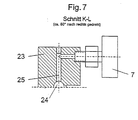
- FIG. 7 which represents a section in FIG. 3 along the line KL, shows the pressure gauge 7 for the cylinder pressure.
- the gauge 7 is connected to the central bore 24 via a high pressure communication passage 25 bored in the valve body 23.
- FIG. 8 shows a preferred embodiment of the invention.
- a device 11 for pressure reduction is integrated.
- the entire system thus receives a two-stage pressure control, whereby the consumption pressure can be controlled more accurately.
- the influence of the current tank pressure on the regulated consumption pressure is lower.
- the bottle closure device 11 is shown in detail in FIG. Figure 9 shows a section along the line K-L-M in Figure 8.
- the actuator 5 is designed as a lever. By turning the lever 5 by an angle 12 of 180 °, the closure device 11 is brought from the open to the closed position.
- the closure device 11 is connected via an oblique connection channel to the central bore 24 on the gas side.
- the closure device 11 corresponds in essential parts to the pressure reducer 60 described with reference to Figures 5 and 6.
- a closure element 71 is acted upon in the open state by the pressure of the channel 24 flowing from the gas cylinder high pressure gas and the spring force of two springs 72, 73.
- the spring preloads are adjusted so that the gas pressure in the bottle is lowered from 200 or 300 bar to about 30 bar.
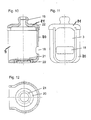
- the protective cap 2 is designed substantially cylindrical and consists of two parts: a lower part 80 and a lid 81.
- the two parts 80, 81 are designed so that they have no undercuts up or down. In this way, the protective cap parts 80, 81 are easily made of plastic, for example by injection molding.
- a metallic reinforcing member 20 is incorporated during the manufacturing process, usually poured.
- the lower part 80 is screwed onto the bottleneck thread of the gas cylinder.
- the lower part 80 has on one side an access opening 3, which has an opening angle of 120 °, starting from the central axis of the lower part 80.
- a further recess 18 is provided which can serve as a carrying handle.
- the cover 81 is connected by means of fastening screws 22 with the lower part 80.
- a knob 19 is attached to the top of the lid 81.
Landscapes
- Engineering & Computer Science (AREA)
- Physics & Mathematics (AREA)
- Fluid Mechanics (AREA)
- General Physics & Mathematics (AREA)
- Automation & Control Theory (AREA)
- Mechanical Engineering (AREA)
- General Engineering & Computer Science (AREA)
- Filling Or Discharging Of Gas Storage Vessels (AREA)
- Fluid-Damping Devices (AREA)
Claims (11)
- Robinetterie de bouteille à gaz, comportant des éléments de commande et d'affichage prévus pour l'utilisateur, qui comprennent au moins un organe d'actionnement pour un dispositif de fermeture de la bouteille, une tête de réglage pour un réducteur de pression et un raccord de prélèvement de gaz, dans laquelle tous les éléments de commande et d'affichage prévus pour l'utilisateur (5, 6, 7, 8, 9) sont disposés à l'intérieur d'un secteur cylindrique (4), caractérisée en ce que l'axe du cylindre du secteur cylindrique (4) est situé sur l'axe de la bouteille et en ce que son angle d'ouverture ne vaut pas plus de 150°, de préférence pas plus de 120°, et de préférence encore pas plus de 90°, et en ce qu'il est prévu un raccord de remplissage (10) pour le remplissage de la bouteille à gaz, dans laquelle l'ouverture de raccordement du raccord de remplissage (10) se trouve dans un plan perpendiculaire à l'axe de la bouteille.
- Robinetterie de bouteille à gaz selon la revendication 1, caractérisée en ce que les éléments de commande et d'affichage comprennent un dispositif d'affichage de la pression (7) pour la pression de la bouteille et un dispositif d'affichage de la pression (8) pour la pression d'utilisation.
- Robinetterie de bouteille à gaz selon l'une des revendications 1 ou 2, caractérisée en ce qu'un dispositif de réduction de la pression est intégré dans le dispositif de fermeture de la bouteille (11).
- Robinetterie de bouteille à gaz selon la revendication 3, caractérisée en ce qu'il est prévu un dispositif de réduction de la pression à 10 à 40 bars, de préférence à 20 à 30 bars.
- Robinetterie de bouteille à gaz selon l'une quelconque des revendications 1 à 4, caractérisée en ce que l'angle d'actionnement (12) de l'organe d'actionnement (5) du dispositif de fermeture de la bouteille (11, 40) ne vaut pas plus de 270°, de préférence pas plus de 180°, et de préférence encore pas plus de 150°.
- Robinetterie de bouteille à gaz selon l'une quelconque des revendications 1 à 5, caractérisée en ce que l'organe d'actionnement (5) du dispositif de fermeture de la bouteille (11, 40) se cale par encliquetage dans ses positions extrêmes.
- Robinetterie de bouteille à gaz selon l'une quelconque des revendications 1 à 6, caractérisée en ce que l'organe d'actionnement (5) du dispositif de fermeture de la bouteille (40) est un bouton rotatif.
- Bouteille à gaz avec une robinetterie de bouteille à gaz selon l'une quelconque des revendications 1 à 7, caractérisée en ce qu'il est prévu un capuchon de protection (2) pour la robinetterie de bouteille à gaz, qui présente au moins une, de préférence exactement une ouverture d'accès (3) pour les éléments de commande et d'affichage (5, 6, 7, 8, 9) prévus pour l'utilisateur.
- Bouteille à gaz selon la revendication 8, caractérisée en ce que le capuchon de protection (2) est fermé vers le haut et/ou présente une ouverture d'évacuation dans le bas.
- Bouteille à gaz selon l'une des revendications 8 ou 9, caractérisée en ce que le capuchon de protection (2) se compose d'une partie inférieure (80) et d'une partie supérieure (81), dans laquelle la partie inférieure (80) ne présente pas de contre-dépouille vers le haut et la partie supérieure (81) ne présente pas de contre-dépouille vers le bas.
- Bouteille à gaz selon l'une quelconque des revendications 8 à 10, caractérisée en ce que le capuchon de protection (2) comporte un évidement (18) convenant comme poignée et/ou la partie supérieure (81) du capuchon de protection (2) présente un bouchon (19).
Priority Applications (1)
| Application Number | Priority Date | Filing Date | Title |
|---|---|---|---|
| EP99125257A EP1013986B1 (fr) | 1998-12-18 | 1999-12-17 | Robinetterie de bouteille à gaz |
Applications Claiming Priority (7)
| Application Number | Priority Date | Filing Date | Title |
|---|---|---|---|
| DE19858746 | 1998-12-18 | ||
| DE19858746 | 1998-12-18 | ||
| DE19912489 | 1999-03-19 | ||
| DE19912489A DE19912489A1 (de) | 1998-12-18 | 1999-03-19 | Gasflaschenarmatur |
| EP99106956 | 1999-04-08 | ||
| EP99106956 | 1999-04-08 | ||
| EP99125257A EP1013986B1 (fr) | 1998-12-18 | 1999-12-17 | Robinetterie de bouteille à gaz |
Publications (2)
| Publication Number | Publication Date |
|---|---|
| EP1013986A1 EP1013986A1 (fr) | 2000-06-28 |
| EP1013986B1 true EP1013986B1 (fr) | 2007-08-15 |
Family
ID=38438669
Family Applications (1)
| Application Number | Title | Priority Date | Filing Date |
|---|---|---|---|
| EP99125257A Expired - Lifetime EP1013986B1 (fr) | 1998-12-18 | 1999-12-17 | Robinetterie de bouteille à gaz |
Country Status (4)
| Country | Link |
|---|---|
| EP (1) | EP1013986B1 (fr) |
| AT (1) | ATE370366T1 (fr) |
| DE (1) | DE59914457D1 (fr) |
| ES (1) | ES2292222T3 (fr) |
Families Citing this family (3)
| Publication number | Priority date | Publication date | Assignee | Title |
|---|---|---|---|---|
| FR2791757B1 (fr) * | 1999-04-01 | 2001-06-15 | Air Liquide | Chapeau ouvert composite de grandes bouteilles de gaz industriels et medicaux |
| EP2835573B1 (fr) | 2013-08-06 | 2019-11-20 | Air Products And Chemicals, Inc. | Agencement de levage de garde de régulateur de cylindre |
| FR3018581B1 (fr) | 2014-03-12 | 2017-01-27 | Air Liquide | Capotage avec rebord de protection de l'organe de commande rotatif d'un bloc robinet de recipient de gaz |
Family Cites Families (5)
| Publication number | Priority date | Publication date | Assignee | Title |
|---|---|---|---|---|
| FR2399610A1 (fr) * | 1977-08-01 | 1979-03-02 | Vieyres Gabriel | Dispositif pour assembler, dans un recipient pour fluide sous pression, deux elements entoures d'une tulipe protectrice |
| FR2507574A1 (fr) * | 1981-06-16 | 1982-12-17 | Mousserolles Fonderies Atel | Chapeau pour bouteille de stockage de gaz liquefie |
| SE456558B (sv) * | 1987-01-13 | 1988-10-17 | Aga Ab | Integrerad ventilanordning for i forsta hand gasterapi |
| FR2706051B1 (fr) * | 1993-06-03 | 1995-07-28 | Taema | Ensemble de commande de distribution de gaz et bouteille de gaz équipée d'un tel ensemble. |
| FR2734341B1 (fr) * | 1995-05-18 | 1997-06-20 | Taema | Installation de fourniture de gaz sous basse pression |
-
1999
- 1999-12-17 EP EP99125257A patent/EP1013986B1/fr not_active Expired - Lifetime
- 1999-12-17 DE DE59914457T patent/DE59914457D1/de not_active Expired - Lifetime
- 1999-12-17 AT AT99125257T patent/ATE370366T1/de active
- 1999-12-17 ES ES99125257T patent/ES2292222T3/es not_active Expired - Lifetime
Non-Patent Citations (1)
| Title |
|---|
| None * |
Also Published As
| Publication number | Publication date |
|---|---|
| ES2292222T3 (es) | 2008-03-01 |
| ATE370366T1 (de) | 2007-09-15 |
| DE59914457D1 (de) | 2007-09-27 |
| EP1013986A1 (fr) | 2000-06-28 |
Similar Documents
| Publication | Publication Date | Title |
|---|---|---|
| DE69116029T2 (de) | Mit Ventilen kombiniertes modulares Steuerpult | |
| DE69515839T2 (de) | Steuereinheit für gasverteilung und gasbehälter ausgestattet mit solcher einheit | |
| EP0226532B1 (fr) | Cellule de commutation électrique avec une commande de déplacement pour un appareil de commutation mobile | |
| EP0296618B1 (fr) | Réservoir d'essence autoserrant | |
| DE102008018892A1 (de) | Verriegelungsvorrichtung für ein Installationsschaltgerät | |
| WO2002053966A2 (fr) | Recipient pressurise a regulation integree d'un fluide comprime | |
| DE19912489A1 (de) | Gasflaschenarmatur | |
| EP1013986A1 (fr) | Robinetterie de bouteille à gaz | |
| EP0496104B1 (fr) | Soupape mélangeur sanitaire | |
| EP1092650B1 (fr) | Capuchon protecteur pour un dispositif d'actionnement ainsi q'un systeme d'emballage et de distribution pour fluides | |
| DE2946874C2 (fr) | ||
| DE3045568C2 (de) | Motorantrieb für Niederspannungs-Schutzschalter | |
| EP0716726A1 (fr) | Dispositif de mise a l'air libre pourvu d'un aimant de commande | |
| DE3304942C2 (de) | Elektrischer Schalter | |
| DE4318837C2 (de) | Vorrichtung zum Auslösen und Unterbrechen des Wasserlaufs aus einer Wasseraustrittsöffnung | |
| EP2198684A1 (fr) | Boîtier de soupape de commande et support de buses pour dispositif de pulvérisation pour la technique agricole | |
| DE3501297A1 (de) | Motorzentralverteilung | |
| DE3417726C2 (fr) | ||
| DE3030747C2 (de) | Ventil | |
| DE19652682C1 (de) | Sicherheitsabsperrarmatur und Verfahren zum Befüllen eines Druckspeicherbehälters mit einem Fluid | |
| DE2756156C2 (de) | Gehäuse, das mit einem lösbar befestigten Deckel besetzt ist, der den mit elektrischen Geräten ausgestatteten Gehäuseinnenraum druckfest abschließt | |
| DE4022147C2 (de) | Narkosemittelverdunster mit einem Belastungsindikator für die Dosiervorrichtung | |
| DE29623997U1 (de) | Elektrisches Installationsgerät | |
| EP0275913B1 (fr) | Dispositif de commutation électrique | |
| DE2911252C2 (de) | Schnappschalter mit Kontaktbrücken |
Legal Events
| Date | Code | Title | Description |
|---|---|---|---|
| PUAI | Public reference made under article 153(3) epc to a published international application that has entered the european phase |
Free format text: ORIGINAL CODE: 0009012 |
|
| AK | Designated contracting states |
Kind code of ref document: A1 Designated state(s): AT BE CH CY DE DK ES FI FR GB GR IE IT LI LU MC NL PT SE |
|
| AX | Request for extension of the european patent |
Free format text: AL;LT;LV;MK;RO;SI |
|
| 17P | Request for examination filed |
Effective date: 20000928 |
|
| RAP1 | Party data changed (applicant data changed or rights of an application transferred) |
Owner name: LINDE GAS AG |
|
| AKX | Designation fees paid |
Free format text: AT BE CH CY DE DK ES FI FR GB GR IE IT LI LU MC NL PT SE |
|
| RAP1 | Party data changed (applicant data changed or rights of an application transferred) |
Owner name: LINDE AG |
|
| GRAP | Despatch of communication of intention to grant a patent |
Free format text: ORIGINAL CODE: EPIDOSNIGR1 |
|
| GRAS | Grant fee paid |
Free format text: ORIGINAL CODE: EPIDOSNIGR3 |
|
| GRAA | (expected) grant |
Free format text: ORIGINAL CODE: 0009210 |
|
| AK | Designated contracting states |
Kind code of ref document: B1 Designated state(s): AT BE CH CY DE DK ES FI FR GB GR IE IT LI LU MC NL PT SE |
|
| REG | Reference to a national code |
Ref country code: GB Ref legal event code: FG4D Free format text: NOT ENGLISH |
|
| REG | Reference to a national code |
Ref country code: CH Ref legal event code: EP |
|
| REG | Reference to a national code |
Ref country code: IE Ref legal event code: FG4D Free format text: LANGUAGE OF EP DOCUMENT: GERMAN |
|
| REF | Corresponds to: |
Ref document number: 59914457 Country of ref document: DE Date of ref document: 20070927 Kind code of ref document: P |
|
| PG25 | Lapsed in a contracting state [announced via postgrant information from national office to epo] |
Ref country code: NL Free format text: LAPSE BECAUSE OF FAILURE TO SUBMIT A TRANSLATION OF THE DESCRIPTION OR TO PAY THE FEE WITHIN THE PRESCRIBED TIME-LIMIT Effective date: 20070815 Ref country code: FI Free format text: LAPSE BECAUSE OF FAILURE TO SUBMIT A TRANSLATION OF THE DESCRIPTION OR TO PAY THE FEE WITHIN THE PRESCRIBED TIME-LIMIT Effective date: 20070815 |
|
| NLV1 | Nl: lapsed or annulled due to failure to fulfill the requirements of art. 29p and 29m of the patents act | ||
| ET | Fr: translation filed | ||
| REG | Reference to a national code |
Ref country code: CH Ref legal event code: PFA Owner name: LINDE AKTIENGESELLSCHAFT Free format text: LINDE AG#ABRAHAM-LINCOLN-STRASSE 21#65189 WIESBADEN (DE) -TRANSFER TO- LINDE AKTIENGESELLSCHAFT#LEOPOLDSTRASSE 252#80807 MUENCHEN (DE) |
|
| REG | Reference to a national code |
Ref country code: ES Ref legal event code: FG2A Ref document number: 2292222 Country of ref document: ES Kind code of ref document: T3 |
|
| GBV | Gb: ep patent (uk) treated as always having been void in accordance with gb section 77(7)/1977 [no translation filed] |
Effective date: 20070815 |
|
| REG | Reference to a national code |
Ref country code: IE Ref legal event code: FD4D |
|
| PG25 | Lapsed in a contracting state [announced via postgrant information from national office to epo] |
Ref country code: GR Free format text: LAPSE BECAUSE OF FAILURE TO SUBMIT A TRANSLATION OF THE DESCRIPTION OR TO PAY THE FEE WITHIN THE PRESCRIBED TIME-LIMIT Effective date: 20071116 Ref country code: DK Free format text: LAPSE BECAUSE OF FAILURE TO SUBMIT A TRANSLATION OF THE DESCRIPTION OR TO PAY THE FEE WITHIN THE PRESCRIBED TIME-LIMIT Effective date: 20070815 |
|
| PG25 | Lapsed in a contracting state [announced via postgrant information from national office to epo] |
Ref country code: PT Free format text: LAPSE BECAUSE OF FAILURE TO SUBMIT A TRANSLATION OF THE DESCRIPTION OR TO PAY THE FEE WITHIN THE PRESCRIBED TIME-LIMIT Effective date: 20080115 Ref country code: IE Free format text: LAPSE BECAUSE OF FAILURE TO SUBMIT A TRANSLATION OF THE DESCRIPTION OR TO PAY THE FEE WITHIN THE PRESCRIBED TIME-LIMIT Effective date: 20070815 Ref country code: GB Free format text: LAPSE BECAUSE OF FAILURE TO SUBMIT A TRANSLATION OF THE DESCRIPTION OR TO PAY THE FEE WITHIN THE PRESCRIBED TIME-LIMIT Effective date: 20070815 |
|
| PLBE | No opposition filed within time limit |
Free format text: ORIGINAL CODE: 0009261 |
|
| STAA | Information on the status of an ep patent application or granted ep patent |
Free format text: STATUS: NO OPPOSITION FILED WITHIN TIME LIMIT |
|
| BERE | Be: lapsed |
Owner name: LINDE A.G. Effective date: 20071231 |
|
| PG25 | Lapsed in a contracting state [announced via postgrant information from national office to epo] |
Ref country code: SE Free format text: LAPSE BECAUSE OF FAILURE TO SUBMIT A TRANSLATION OF THE DESCRIPTION OR TO PAY THE FEE WITHIN THE PRESCRIBED TIME-LIMIT Effective date: 20071115 |
|
| 26N | No opposition filed |
Effective date: 20080516 |
|
| PG25 | Lapsed in a contracting state [announced via postgrant information from national office to epo] |
Ref country code: MC Free format text: LAPSE BECAUSE OF NON-PAYMENT OF DUE FEES Effective date: 20071231 |
|
| PG25 | Lapsed in a contracting state [announced via postgrant information from national office to epo] |
Ref country code: BE Free format text: LAPSE BECAUSE OF NON-PAYMENT OF DUE FEES Effective date: 20071231 |
|
| REG | Reference to a national code |
Ref country code: FR Ref legal event code: CA |
|
| PG25 | Lapsed in a contracting state [announced via postgrant information from national office to epo] |
Ref country code: CY Free format text: LAPSE BECAUSE OF FAILURE TO SUBMIT A TRANSLATION OF THE DESCRIPTION OR TO PAY THE FEE WITHIN THE PRESCRIBED TIME-LIMIT Effective date: 20070815 |
|
| PG25 | Lapsed in a contracting state [announced via postgrant information from national office to epo] |
Ref country code: LU Free format text: LAPSE BECAUSE OF NON-PAYMENT OF DUE FEES Effective date: 20071217 |
|
| PG25 | Lapsed in a contracting state [announced via postgrant information from national office to epo] |
Ref country code: IT Free format text: LAPSE BECAUSE OF NON-PAYMENT OF DUE FEES Effective date: 20071231 |
|
| PGFP | Annual fee paid to national office [announced via postgrant information from national office to epo] |
Ref country code: AT Payment date: 20131126 Year of fee payment: 15 Ref country code: DE Payment date: 20131211 Year of fee payment: 15 |
|
| PGFP | Annual fee paid to national office [announced via postgrant information from national office to epo] |
Ref country code: FR Payment date: 20131209 Year of fee payment: 15 Ref country code: ES Payment date: 20131112 Year of fee payment: 15 |
|
| REG | Reference to a national code |
Ref country code: DE Ref legal event code: R119 Ref document number: 59914457 Country of ref document: DE |
|
| REG | Reference to a national code |
Ref country code: AT Ref legal event code: MM01 Ref document number: 370366 Country of ref document: AT Kind code of ref document: T Effective date: 20141217 |
|
| REG | Reference to a national code |
Ref country code: FR Ref legal event code: ST Effective date: 20150831 |
|
| PG25 | Lapsed in a contracting state [announced via postgrant information from national office to epo] |
Ref country code: DE Free format text: LAPSE BECAUSE OF NON-PAYMENT OF DUE FEES Effective date: 20150701 |
|
| PG25 | Lapsed in a contracting state [announced via postgrant information from national office to epo] |
Ref country code: FR Free format text: LAPSE BECAUSE OF NON-PAYMENT OF DUE FEES Effective date: 20141231 Ref country code: AT Free format text: LAPSE BECAUSE OF NON-PAYMENT OF DUE FEES Effective date: 20141217 |
|
| REG | Reference to a national code |
Ref country code: ES Ref legal event code: FD2A Effective date: 20160126 |
|
| PGFP | Annual fee paid to national office [announced via postgrant information from national office to epo] |
Ref country code: CH Payment date: 20151211 Year of fee payment: 17 |
|
| PG25 | Lapsed in a contracting state [announced via postgrant information from national office to epo] |
Ref country code: ES Free format text: LAPSE BECAUSE OF NON-PAYMENT OF DUE FEES Effective date: 20141218 |
|
| REG | Reference to a national code |
Ref country code: CH Ref legal event code: PL |
|
| PG25 | Lapsed in a contracting state [announced via postgrant information from national office to epo] |
Ref country code: LI Free format text: LAPSE BECAUSE OF NON-PAYMENT OF DUE FEES Effective date: 20161231 Ref country code: CH Free format text: LAPSE BECAUSE OF NON-PAYMENT OF DUE FEES Effective date: 20161231 |