EP1013988A2 - Leuchtenkopf einer Strahlerleuchte - Google Patents
Leuchtenkopf einer Strahlerleuchte Download PDFInfo
- Publication number
- EP1013988A2 EP1013988A2 EP99124529A EP99124529A EP1013988A2 EP 1013988 A2 EP1013988 A2 EP 1013988A2 EP 99124529 A EP99124529 A EP 99124529A EP 99124529 A EP99124529 A EP 99124529A EP 1013988 A2 EP1013988 A2 EP 1013988A2
- Authority
- EP
- European Patent Office
- Prior art keywords
- lamp
- head according
- housing
- carrier part
- holding part
- Prior art date
- Legal status (The legal status is an assumption and is not a legal conclusion. Google has not performed a legal analysis and makes no representation as to the accuracy of the status listed.)
- Withdrawn
Links
- 238000003780 insertion Methods 0.000 claims abstract description 16
- 230000037431 insertion Effects 0.000 claims abstract description 16
- 239000002184 metal Substances 0.000 claims description 2
- 239000000463 material Substances 0.000 description 3
- 230000001066 destructive effect Effects 0.000 description 2
- 230000001419 dependent effect Effects 0.000 description 1
- 238000011161 development Methods 0.000 description 1
- 230000018109 developmental process Effects 0.000 description 1
- 230000000694 effects Effects 0.000 description 1
- 229910052736 halogen Inorganic materials 0.000 description 1
- 150000002367 halogens Chemical class 0.000 description 1
- 230000001771 impaired effect Effects 0.000 description 1
- 238000001746 injection moulding Methods 0.000 description 1
- 210000002105 tongue Anatomy 0.000 description 1
Images


Classifications
-
- F—MECHANICAL ENGINEERING; LIGHTING; HEATING; WEAPONS; BLASTING
- F21—LIGHTING
- F21V—FUNCTIONAL FEATURES OR DETAILS OF LIGHTING DEVICES OR SYSTEMS THEREOF; STRUCTURAL COMBINATIONS OF LIGHTING DEVICES WITH OTHER ARTICLES, NOT OTHERWISE PROVIDED FOR
- F21V17/00—Fastening of component parts of lighting devices, e.g. shades, globes, refractors, reflectors, filters, screens, grids or protective cages
- F21V17/08—Fastening of component parts of lighting devices, e.g. shades, globes, refractors, reflectors, filters, screens, grids or protective cages onto the supporting or suspending arrangements of the lighting device, e.g. power cords, standards
-
- F—MECHANICAL ENGINEERING; LIGHTING; HEATING; WEAPONS; BLASTING
- F21—LIGHTING
- F21V—FUNCTIONAL FEATURES OR DETAILS OF LIGHTING DEVICES OR SYSTEMS THEREOF; STRUCTURAL COMBINATIONS OF LIGHTING DEVICES WITH OTHER ARTICLES, NOT OTHERWISE PROVIDED FOR
- F21V19/00—Fastening of light sources or lamp holders
Definitions
- the invention relates to a lamp head Spotlight with the features from the generic term of claim 1.
- Such lamp heads are known per se. Both Known lamp heads are attached to the Carrier part in the spotlight housing by means of a fastening device, designed as a screw connection is. This is generally the case in Spotlight housing protruding end of the support part threaded, and the holding part is as Screw nut trained in the interior of the Spotlight housing screwed onto the thread of the carrier part until it adheres to the inner surface of the jacket of the spotlight housing and thus together with the counter stops, which are on the outer surface of the jacket of the spotlight housing, the carrier part in the Fixing opening fixed.
- a fastening device designed as a screw connection is.
- a lamp head lamp holder to connect the carrier part directly to each other, where, for example, as in DE 43 35 042 A1 described, the lamp holder have a foot part can from the interior of the spotlight housing in the mounting hole is inserted and that behind gripping the edge of the mounting opening Has locking means and that then from the outside Locking part inserted in the foot part and locked becomes.
- Such a fastening device is not easy on all shapes and structures adaptable to the outer surface of a spotlight housing.
- the Don't run out of space around the lamp holder with foot section through the lamp insertion opening into the interior of the spotlight housing to bring them there insert into the mounting hole.
- the invention has for its object a Luminaire head with the features from the generic term of claim 1 so that one does not only positive connection, but positive connection between the support part and the radiator housing and that the fastening device by simple constructive measures on very narrow designs of Spotlight housings and different shapes and Structures of the inner surface and outer surface a spotlight housing is adaptable and in in any case to a safe and secure connection leads, which can also be designed so that it no longer non-destructive with conventional tools is solvable.
- this fastening device consists in that individual parts, such as the carrier part, can be trained as standard parts that by means of special to the shape and structure of Spotlight housings adapted holding parts for very different Shapes and structures of spotlight housings can be used, by the arrangement the counter stops on one to the support part Fitable fitting outside the spotlight housing again a possibility is created, the fastening device also to very different ones Structures and shapes of the outer surface of the Adapt spotlight housing.
- appropriate locking elements ensured on the holding part be that the holding part is no longer non-destructive can be removed.
- this type of fastener still the advantage that they can be used even in very narrow designs of the spotlight housing can be installed in a simple manner is because the insertion of the holding part through the mounting hole in a straight line motion can be done with little maneuvering space inside of the spotlight housing is required.
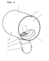
- the lamp head shown in FIGS. 1 to 5 for has a spotlight for low-voltage halogen lamps a radiator housing 1 with a substantially cylindrical jacket with a jacket inner surface 1.3 and a jacket outer surface 1.4.
- the Spotlight housing has a lamp insertion opening on its front 1.1 and at the bottom of his Shell surface a fastening opening 1.2.
- On this radiator housing 1 becomes the leads receiving, essentially tubular Carrier part 2 attached.
- this carrier part 2 is also its an end section 2.1, which the fastening area represents in the mounting opening 1.2 of the Spotlight housing 1 used.
- the carrier part 2 Serve for attachment arranged on the fastening area 2.1 of the carrier part 2 flange-like projections 3, which on the fastening area arranged, opposite each other and parallel to each other and essentially in the direction of lamp insertion LE running guide surfaces limit.
- the flange-like Projections 3 laterally on two opposite one another Edges of the fastening area 2.1 arranged and run in a direction QL transverse to Lamp insertion direction LE and essentially parallel to the level of the mounting opening 1.2.
- a fitting 5 is attached to the carrier part 2, that on the, facing the radiator housing 1 Side is provided with a flange 5.1 itself (see Fig. 3) when inserted on the outer surface 1.4 of the spotlight housing 1 creates.
- the outer end portion of the carrier part 2 is as an upper joint part 2.2 trained that together with a corresponding lower part of a joint not illustrated light arm is connectable.
- Fig. 2 shows how the adapter 5 to the carrier part 2nd is scheduled.
- the attachment takes place through the attachment opening 1.2 by a holding part 4, which two in parallel has mutually extending fork tines 4.1 and 4.2.
- the fork opening width is at least as large as the distance d (Fig. 1) between the guide surfaces 2.3 on the carrier part 2, but smaller than the distance D the outer ends of the protrusions 3.
- the forks 4.1 and 4.2 have wedge-shaped rises Surfaces 4.21 on (see also the embodiment 6) and have on the inside at the front end locking hook 4.12 and after front guiding surfaces 4.11.
- the holding part 4 by the Lamp insertion opening 1.1 inserted into the lamp housing and in the area of the guide surfaces 2.3 pushed onto the carrier part 2 so that it has the projections 3 engages behind and in that shown in Fig. 4 inserted state between the projections 3 and the inner surface 1.3 of the radiator housing 1 is jammed.
- the locking hooks 4.12 snap behind the rear surface of the support member 2, so that Holding part 4 captively fixed in its end position is and a positive connection between Carrier part 2 and lamp housing 1 is created.
- the engagement of the locking hooks 4.12 is made possible by that the holding part 4 at least in the area of Ends of the forks 4.1 and 4.2 elastic properties having.
- the carrier part 2 is on the outer surface 1.4 through the flange ring forming a counterstop 5.1 supported.
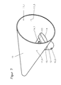
- FIGS. 6 and 7 show another embodiment of a lamp head with a conical spotlight housing 11, the lamp insertion opening 11.1 and has a mounting opening 11.2 and a Inner surface 11.3 and an outer surface 11.4.
- the carrier part is in the fastening opening 11.2 12 used, which on the inside of the lamp housing protruding fastening area 12.1 already described flange-like projections 13, which limit the guide surfaces 12.3.
- On the outer part has the carrier part 12 in turn an upper joint part 12.2.
- To the support part 12 the adapter 15 with its flange ring 15.1 scheduled.
- the holding part 14 that from the lamp insertion opening 11.1 is inserted here, runs in two fork tines 14.1 and 14.2, each wedge-shaped are formed, the inside out outside wedge angle 14.21 is such that the clamping of the holding part 14 between the projections 13 of the carrier part 12 and the inner surface of the jacket 11.3 of the spotlight housing 11 has self-locking.
- the fork tines 14.1 and 14.2 are elastic Properties and have hook-like at their front end Snap elements 14.12, which are used in the State (Fig. 7) behind a rear surface of the carrier part 12 snap into place.
- For guidance when inserting serve on the inside of the forks 14.1 and 14.2 arranged guide surfaces opening towards the front 14.11.
- Fig. 8 shows a variant of the previously discussed Embodiments of a lamp head, in which the Luminaire housing has a jacket that consists of a corrugated material.
- Fig. 8 shows the lamp head 21, which is both a corrugated inner surface 21.3 as well as a corrugated outer surface 21.4 has, with inserted carrier part 22, through the inner channel 22.3, not shown Feed lines are guided.
- On the support member 22 is a fitting 25 attached, the outer surface of the jacket 21.4 of the radiator housing 21 facing surface 25.2 adapted to the structure of the outer jacket surface 21.4 is.
- Luminaire head In the previously explained embodiments of the Luminaire head is provided that in not shown Way the lamp holder for itself in the spotlight housing is attached.
- the fastener shown but also offers the possibility the lamp holder on the inside of the spotlight housing Attach the support part.
- This possibility is in 9 and 10 are shown.
- 9 and 10 show a variant of the embodiment of FIGS. 1 to 5.
- It is a lamp head, which in particular is intended for lamps with a threaded base.
- the Spotlight housing 31 is again essentially cylindrical trained, but there are other housing shapes possible. It has a lamp insertion opening 31.1 and one with a corner in FIG. 9 visible fastening opening 31.2.
- the carrier part is made of two attachable and not over snap connections shown attachable to each other Support part halves 32a and 32b constructed.
- Each of the has two carrier part halves 32a and 32b on their, through the fastening opening 31.2 into the interior of the radiator housing 31 insertable end already explained flange-like projections, of which the the projections 33a assigned to the carrier part half 32a are visible in Fig. 9. Limit these protrusions 33a as described, guide surfaces 32.1a, which in assembled state of the two carrier part halves on opposite sides of the support part are arranged parallel to each other.
- a lamp holder 36 is arranged on the carrier part.
- the lamp holder 36 is by means of a mounting element 36.1 attached to the support member, which before Assembling the two carrier part halves 32a and 32b inserted between the two carrier part halves becomes.
- the are facing each other Sides of the two halves 32a and 32b Guide and stop surfaces for the mounting element 36.1 so that after assembling and snapping of the two carrier part halves 32a and 32b Lamp holder 36 fixed over the support member 36.1 is connected to the carrier part.
- the carrier part with the lamp holder 36 attached to it is then in the way already described through the mounting opening 31.2 inserted in the spotlight housing 31, where the outer surface of the Spotlight housing 31 facing one side of the Carrier part 32a-32b attached fitting 35 as a stop creates.
- the attachment of the support part with Lamp socket in the spotlight housing 31 then takes place as already described, by a holding part 34, which Forks 34.1 and 34.2 has on their free ends, as already described, carry snap hooks.
- the holding part 34 is so on the guide surfaces 32.1a pushed on that the projections 33a engage behind and the locking hooks behind the carrier part engage so that even in this embodiment a positive connection between the carrier part and the spotlight housing is created.
- On the front of the holding part 34 is in one piece and uniformly arranged a base ring 37, the with the holding part 34 inserted in the spotlight housing 31 is concentric with the lamp holder 36.
- At in the Lamp holder 36 screwed lamp surrounds the Base ring 37 together with parts of the lamp holder as contact protection the operational voltage leading metal base of the lamp.
Landscapes
- Engineering & Computer Science (AREA)
- General Engineering & Computer Science (AREA)
- Fastening Of Light Sources Or Lamp Holders (AREA)
- Lighting Device Outwards From Vehicle And Optical Signal (AREA)
Abstract
Description
Claims (15)
- Leuchtenkopf einer Strahlerleuchte mit einem Strahlergehäuse, in dem eine Lampenfassung angeordnet ist und das an seiner Vorderseite eine Lampeneinsetzöffnung sowie an seiner Mantelfläche eine Befestigungsöffnung besitzt, und mit einem rohrförmigen, die Zuleitungen aufnehmenden Trägerteil, dessen eines Ende durch die Befestigungsöffnung in das Strahlergehäuse hineinragt und mittels einer Befestigungseinrichtung an diesem befestigt ist, wobei die Befestigungseinrichtung einen am in das Strahlergehäuse hineinragenden Endabschnitt des Trägerteils angeordneten Befestigungsbereich sowie ein mit dem Befestigungsbereich zusammenwirkendes Halteteil aufweist, das sich an die Mantelinnenfläche des Strahlergehäuses anlegt, und das Trägerteil Gegenanschläge aufweist, welche sich außerhalb der Befestigungsöffnung an die Mantelaußenfläche des Strahlergehäuses anlegen
dadurch gekennzeichnet, daß der Befestigungsbereich (2.1, 12.1, 22.1) mit mindestens zwei Führungsflächen (2.3 12.3) versehen ist, welche einander gegenüberliegend parallel zueinander und im wesentlichen in Lampeneinsetzrichtung (LE) verlaufen und welche in Richtung auf das innere Ende des Trägerteils (2, 12, 22) hin durch flanschartige Vorsprünge (3, 13, 23) begrenzt sind, die seitlich an zwei einander gegenüberliegenden Kanten des Befestigungsbereichs angeordnet sind und in einer Richtung (QL) quer zur Lampeneinsetzrichtung (LE) und im wesentlichen parallel zur Ebene der Befestigungsöffnung (1.2, 11.2) verlaufen, und daß das Halteteil (4, 14) zwei im wesentlichen parallel zueinander verlaufende Gabelzinken (4.1, 4.2-14.1, 14.2-24.1, 24.2) aufweist, wobei die Gabelöffnungsweite mindestens so groß ist wie der Abstand (d) zwischen den Führungsflächen, aber kleiner als der Abstand (D) der äußeren Enden der Vorsprünge (3, 13, 23). - Leuchtenkopf nach Anspruch 1, insbesondere für Lampen mit Gewindesockel, dadurch gekennzeichnet, daß die Lampenfassung (36) an dem in das Strahlergehäuse (31) hineinragenden Endabschnitt des Trägerteils (32a-32b) angeordnet ist.
- Leuchtenkopf nach Anspruch 1 oder 2, dadurch gekennzeichnet, daß der Befestigungsbereich (2.1, 12.1, 22.1, 32.1a-32.1b) des Trägerteils (2, 12, 22, 32a-32b) durch die Befestigungsöffnung (1.2, 11.2) in das Strahlergehäuse (1, 11, 21) einführbar ist und das Halteteil (4, 14) im Bereich der Führungsflächen (2.3, 12.3) auf das Trägerteil derart aufschiebbar ist, daß es die Vorsprünge (3, 13, 23, 33a-33b) hintergreift und im eingesetzten Zustand zwischen diesen und der Mantelinnenfläche (1.3, 11.3, 21.3) des Strahlergehäuses eingeklemmt ist.
- Leuchtenkopf nach einem der Ansprüche 1 bis 3, dadurch gekennzeichnet, daß mindestens die Gabelzinken (4.1, 4.2; 14.1, 14.2; 24.1, 24.2) des Halteteils (4, 14) mindestens in ihrem vorderen Bereich keilförmig ausgebildet sind.
- Leuchtenkopf nach Anspruch 4, dadurch gekennzeichnet, daß der Keilwinkel (14, 21) des Halteteils (14) derart ist, daß die Klemmung des Halteteils zwischen den Vorsprüngen (13) des Trägerteils und der Mantelinnenfläche (11.3) des Strahlergehäuses (11) Selbsthemmung aufweist.
- Leuchtenkopf nach einem der Ansprüche 1 bis 5, dadurch gekennzeichnet, daß das Halteteil (4, 14) mindestens im Bereich der Enden der Gabelzinken (4.1, 4.2; 14.1,14.2; 24.1, 24.2) elastische Eigenschaften aufweist und an den Enden der Gabelzinken Rastelemente (4.12, 14.12) zum Einrasten hinter eine Fläche des Trägerteils (2, 12) im eingesetzten Zustand des Halteteils (4, 14) angeordnet sind.
- Leuchtenkopf nach einem der Ansprüche 1 bis 6, dadurch gekennzeichnet, daß der Abstand (D) der äußeren Enden der Vorsprünge (3, 13, 23, 33a, 33b) des Trägerteils (2, 12, 22, 32a-32b) kleiner ist als der Durchmesser der Befestigungsöffnung (1.2, 11.2).
- Leuchtenkopf nach einem der Ansprüche 1 bis 7, dadurch gekennzeichnet, daß an der Innenseite der Gabelzinken (4.1, 4.2; 14.1, 14.2) des Halteteils (4, 14) sich nach vorne öffnende Führungsflächen (4.11, 14.11) angeordnet sind.
- Leuchtenkopf nach einem der Ansprüche 1 bis 8, dadurch gekennzeichnet, daß die der Mantelinnenfläche (21.3) des Strahlergehäuses (21) zugekehrte Fläche (24.3) des Halteteils an die Form und/oder Struktur der Mantelinnenfläche (21.3) angepaßt ist.
- Leuchtenkopf nach einem der Ansprüche 1 bis 9, dadurch gekennzeichnet, daß die Gegenanschläge (5.1, 15.1) an einem Paßstück (5, 15) angeordnet sind, welches an das Trägerteil (2, 12) ansetzbar ist.
- Leuchtenkopf nach Anspruch 10, dadurch gekennzeichnet, daß die der Mantelaußenfläche (21.4) des Strahlergehäuses (21) zugekehrte Fläche (25.2) des Paßstücks (25) an die Form und/oder Struktur der Mantelaußenfläche (21.4) angepaßt ist.
- Leuchtenkopf nach Anspruch 9 und 11, dadurch gekennzeichnet, daß das Strahlergehäuse (21) einen Mantel besitzt, der an der Mantelinnenfläche (21.3) und/oder der Mantelaußenfläche (21.4) mit gewellten oder gefalteten Abschnitten versehen ist, an welche das Halteteil (24.1-24.2) bzw. das Paßstück (25) angepaßt sind.
- Leuchtenkopf nach einem der Ansprüche 1 bis 9, dadurch gekennzeichnet, daß die Gegenanschläge einstückig am Trägerteil angeordnet sind.
- Leuchtenkopf nach Anspruch 2 und gegebenenfalls einem der Ansprüche 3 bis 13, dadurch gekennzeichnet, daß das Trägerteil aus zwei Halbschalen (32a, 32b) zusammengesetzt ist, welche die Lampenfassung (36) zwischen sich formschlüssig halten.
- Leuchtenkopf nach Anspruch 2 und gegebenenfalls einem der Ansprüche 3 bis 14, dadurch gekennzeichnet, daß das Halteteil (34) einteilig und stoffeinheitlich mit einem Sockelring (37) verbunden ist, welcher bei in den Leuchtenkopf eingesetzter Lampe gemeinsam mit Teilen der Lampenfassung den Metallsockel der Lampe berührungssicher umgibt.
Applications Claiming Priority (2)
| Application Number | Priority Date | Filing Date | Title |
|---|---|---|---|
| DE1998159400 DE19859400C2 (de) | 1998-12-22 | 1998-12-22 | Vorrichtung zur Befestigung eines Leuchtenkopfs einer Strahlerleuchte an einem Träger |
| DE19859400 | 1998-12-22 |
Publications (2)
| Publication Number | Publication Date |
|---|---|
| EP1013988A2 true EP1013988A2 (de) | 2000-06-28 |
| EP1013988A3 EP1013988A3 (de) | 2001-10-17 |
Family
ID=7892219
Family Applications (1)
| Application Number | Title | Priority Date | Filing Date |
|---|---|---|---|
| EP99124529A Withdrawn EP1013988A3 (de) | 1998-12-22 | 1999-12-09 | Leuchtenkopf einer Strahlerleuchte |
Country Status (2)
| Country | Link |
|---|---|
| EP (1) | EP1013988A3 (de) |
| DE (1) | DE19859400C2 (de) |
Families Citing this family (1)
| Publication number | Priority date | Publication date | Assignee | Title |
|---|---|---|---|---|
| DE202010009487U1 (de) * | 2010-06-24 | 2010-10-07 | Ridi-Leuchten Gmbh | Befestigungsvorrichtung |
Citations (1)
| Publication number | Priority date | Publication date | Assignee | Title |
|---|---|---|---|---|
| DE4335042A1 (de) | 1992-10-27 | 1994-04-28 | Vollmann Gmbh & Co Kg Otto | Elektrische Lampenfassung aus Kunststoff |
Family Cites Families (5)
| Publication number | Priority date | Publication date | Assignee | Title |
|---|---|---|---|---|
| US4774645A (en) * | 1986-11-20 | 1988-09-27 | Ichikoh Industries Limited | Replaceable lamp bulb assembly |
| US5063481A (en) * | 1990-10-15 | 1991-11-05 | Eaton Corporation | Pivot assembly for vehicle headlight position adjustment |
| DE9210721U1 (de) * | 1992-08-11 | 1992-10-15 | Brilliant AG, 2742 Gnarrenburg | Leuchte |
| DE9305897U1 (de) * | 1993-04-20 | 1993-06-17 | Brökelmann, Jaeger & Busse GmbH & Co, 5760 Arnsberg | Lampenfassung |
| IT243856Y1 (it) * | 1998-03-17 | 2002-03-06 | Vlm Spa | Gruppo portalampada e presa a innesto rapido per faretti |
-
1998
- 1998-12-22 DE DE1998159400 patent/DE19859400C2/de not_active Expired - Fee Related
-
1999
- 1999-12-09 EP EP99124529A patent/EP1013988A3/de not_active Withdrawn
Patent Citations (1)
| Publication number | Priority date | Publication date | Assignee | Title |
|---|---|---|---|---|
| DE4335042A1 (de) | 1992-10-27 | 1994-04-28 | Vollmann Gmbh & Co Kg Otto | Elektrische Lampenfassung aus Kunststoff |
Also Published As
| Publication number | Publication date |
|---|---|
| DE19859400C2 (de) | 2001-09-13 |
| EP1013988A3 (de) | 2001-10-17 |
| DE19859400A1 (de) | 2000-07-06 |
Similar Documents
| Publication | Publication Date | Title |
|---|---|---|
| DE69405687T2 (de) | Verbindungbefestigung eines elektrischen Kabels | |
| EP2054977B1 (de) | Steckverbinder für vorderwandmontage oder hinterwandmontage | |
| EP3586415B1 (de) | Steckerkupplung mit zugentlastung für ein verbindungskabel | |
| DE4228383A1 (de) | Kugelgelenkeinheit, Kugelkopf und Kugelpfannenkörper für diese Kugelgelenkeinheit, Zylinderkolbengerät mit daran angebauter Kugelgelenkeinheit, Zylinderkolbengerät mit daran angebautem Kugelpfannenkörper, Verfahren zum Anschließen einer Kugelgelenkeinheit, Verfahren zum Anbringen eines Zylinderkolbengeräts an einer übergeordneten Konstruktion unter Verwendung einer Kugelgelenkeinheit | |
| DE69511766T2 (de) | Kabelzugentlastungsvorrichtung zur Bildung einer rückseitigen Befestigung für einen Verbinder | |
| DE69301453T2 (de) | Rohrbefestigungsanordnung | |
| DE4326477C2 (de) | Vorrichtung zur lösbaren Verbindung einer Führungsstange | |
| DE4335042C2 (de) | Elektrische Lampenfassung aus Kunststoff | |
| DE19735731A1 (de) | Kraftfahrzeugleuchte für den Einbau von außen | |
| DE3816909C2 (de) | ||
| DE4432302C2 (de) | In ein Leuchtengehäuse einsetzbare Lampenbefestigungseinrichtung | |
| DE19730269C2 (de) | Vorrichtung zum Befestigen eines ersten Teils mit einem zweiten Teil | |
| EP0874423B1 (de) | Tragvorrichtung für eine Stromschiene | |
| EP0804698A1 (de) | Griff für eine sanitärarmatur | |
| EP1013988A2 (de) | Leuchtenkopf einer Strahlerleuchte | |
| DE9114246U1 (de) | Leuchte für Kraftfahrzeuge | |
| DE102013101491A1 (de) | Höheneinstellbare Rundstangenführung | |
| DE3001990A1 (de) | Lampenhalter | |
| EP0612122A2 (de) | System zur Realisierung von Lampenfassungen mit Sockel mit eingebautem innerem Einsatzteil | |
| DE19624591C2 (de) | Lampenfassung zur Befestigung in einem Leuchtengehäuse | |
| EP0972954A2 (de) | Befestigungssystem | |
| EP1035619A1 (de) | Stecker | |
| DE69528496T2 (de) | Vorrichtung zur Befestigung von Birnenfassungen an Lampenfüssen | |
| DE19819274C2 (de) | Träger, der einen Leuchtenkopf einer Strahlerleuchte mit einer Leuchtenkonsole durch eine Steckverbindung verbindet, sowie ein Verfahren zum Zusammenbau des Trägers und ein Einziehwerkzeug zur Durchführung des Verfahrens | |
| DE4443545B4 (de) | Steckverbinder |
Legal Events
| Date | Code | Title | Description |
|---|---|---|---|
| PUAI | Public reference made under article 153(3) epc to a published international application that has entered the european phase |
Free format text: ORIGINAL CODE: 0009012 |
|
| AK | Designated contracting states |
Kind code of ref document: A2 Designated state(s): AT BE CH CY DE DK ES FI FR GB GR IE IT LI LU MC NL PT SE |
|
| AX | Request for extension of the european patent |
Free format text: AL;LT;LV;MK;RO;SI |
|
| PUAL | Search report despatched |
Free format text: ORIGINAL CODE: 0009013 |
|
| AK | Designated contracting states |
Kind code of ref document: A3 Designated state(s): AT BE CH CY DE DK ES FI FR GB GR IE IT LI LU MC NL PT SE |
|
| AX | Request for extension of the european patent |
Free format text: AL;LT;LV;MK;RO;SI |
|
| RIC1 | Information provided on ipc code assigned before grant |
Free format text: 7F 21V 19/00 A, 7F 21V 21/116 B |
|
| AKX | Designation fees paid | ||
| REG | Reference to a national code |
Ref country code: DE Ref legal event code: 8566 |
|
| STAA | Information on the status of an ep patent application or granted ep patent |
Free format text: STATUS: THE APPLICATION IS DEEMED TO BE WITHDRAWN |
|
| 18D | Application deemed to be withdrawn |
Effective date: 20020418 |