EP1014030A1 - Table de mesure x/y pour détermination de coordonnées - Google Patents
Table de mesure x/y pour détermination de coordonnées Download PDFInfo
- Publication number
- EP1014030A1 EP1014030A1 EP99124980A EP99124980A EP1014030A1 EP 1014030 A1 EP1014030 A1 EP 1014030A1 EP 99124980 A EP99124980 A EP 99124980A EP 99124980 A EP99124980 A EP 99124980A EP 1014030 A1 EP1014030 A1 EP 1014030A1
- Authority
- EP
- European Patent Office
- Prior art keywords
- measuring table
- bolts
- mirror body
- measuring
- countersink
- Prior art date
- Legal status (The legal status is an assumption and is not a legal conclusion. Google has not performed a legal analysis and makes no representation as to the accuracy of the status listed.)
- Granted
Links
Images

Classifications
-
- G—PHYSICS
- G01—MEASURING; TESTING
- G01B—MEASURING LENGTH, THICKNESS OR SIMILAR LINEAR DIMENSIONS; MEASURING ANGLES; MEASURING AREAS; MEASURING IRREGULARITIES OF SURFACES OR CONTOURS
- G01B9/00—Measuring instruments characterised by the use of optical techniques
- G01B9/02—Interferometers
- G01B9/02015—Interferometers characterised by the beam path configuration
- G01B9/02027—Two or more interferometric channels or interferometers
-
- H—ELECTRICITY
- H10—SEMICONDUCTOR DEVICES; ELECTRIC SOLID-STATE DEVICES NOT OTHERWISE PROVIDED FOR
- H10P—GENERIC PROCESSES OR APPARATUS FOR THE MANUFACTURE OR TREATMENT OF DEVICES COVERED BY CLASS H10
- H10P74/00—Testing or measuring during manufacture or treatment of wafers, substrates or devices
-
- G—PHYSICS
- G01—MEASURING; TESTING
- G01B—MEASURING LENGTH, THICKNESS OR SIMILAR LINEAR DIMENSIONS; MEASURING ANGLES; MEASURING AREAS; MEASURING IRREGULARITIES OF SURFACES OR CONTOURS
- G01B5/00—Measuring arrangements characterised by the use of mechanical techniques
- G01B5/0011—Arrangements for eliminating or compensation of measuring errors due to temperature or weight
- G01B5/0016—Arrangements for eliminating or compensation of measuring errors due to temperature or weight due to weight
-
- G—PHYSICS
- G01—MEASURING; TESTING
- G01B—MEASURING LENGTH, THICKNESS OR SIMILAR LINEAR DIMENSIONS; MEASURING ANGLES; MEASURING AREAS; MEASURING IRREGULARITIES OF SURFACES OR CONTOURS
- G01B9/00—Measuring instruments characterised by the use of optical techniques
- G01B9/02—Interferometers
- G01B9/02015—Interferometers characterised by the beam path configuration
- G01B9/02017—Interferometers characterised by the beam path configuration with multiple interactions between the target object and light beams, e.g. beam reflections occurring from different locations
- G01B9/02021—Interferometers characterised by the beam path configuration with multiple interactions between the target object and light beams, e.g. beam reflections occurring from different locations contacting different faces of object, e.g. opposite faces
-
- G—PHYSICS
- G01—MEASURING; TESTING
- G01B—MEASURING LENGTH, THICKNESS OR SIMILAR LINEAR DIMENSIONS; MEASURING ANGLES; MEASURING AREAS; MEASURING IRREGULARITIES OF SURFACES OR CONTOURS
- G01B9/00—Measuring instruments characterised by the use of optical techniques
- G01B9/02—Interferometers
- G01B9/02049—Interferometers characterised by particular mechanical design details
-
- G—PHYSICS
- G01—MEASURING; TESTING
- G01B—MEASURING LENGTH, THICKNESS OR SIMILAR LINEAR DIMENSIONS; MEASURING ANGLES; MEASURING AREAS; MEASURING IRREGULARITIES OF SURFACES OR CONTOURS
- G01B9/00—Measuring instruments characterised by the use of optical techniques
- G01B9/02—Interferometers
- G01B9/02049—Interferometers characterised by particular mechanical design details
- G01B9/02052—Protecting, e.g. shock absorbing, arrangements
-
- G—PHYSICS
- G01—MEASURING; TESTING
- G01B—MEASURING LENGTH, THICKNESS OR SIMILAR LINEAR DIMENSIONS; MEASURING ANGLES; MEASURING AREAS; MEASURING IRREGULARITIES OF SURFACES OR CONTOURS
- G01B9/00—Measuring instruments characterised by the use of optical techniques
- G01B9/02—Interferometers
- G01B9/02055—Reduction or prevention of errors; Testing; Calibration
- G01B9/0207—Error reduction by correction of the measurement signal based on independently determined error sources, e.g. using a reference interferometer
-
- H—ELECTRICITY
- H10—SEMICONDUCTOR DEVICES; ELECTRIC SOLID-STATE DEVICES NOT OTHERWISE PROVIDED FOR
- H10P—GENERIC PROCESSES OR APPARATUS FOR THE MANUFACTURE OR TREATMENT OF DEVICES COVERED BY CLASS H10
- H10P72/00—Handling or holding of wafers, substrates or devices during manufacture or treatment thereof
- H10P72/50—Handling or holding of wafers, substrates or devices during manufacture or treatment thereof for positioning, orientation or alignment
- H10P72/53—Handling or holding of wafers, substrates or devices during manufacture or treatment thereof for positioning, orientation or alignment using optical controlling means
-
- Y—GENERAL TAGGING OF NEW TECHNOLOGICAL DEVELOPMENTS; GENERAL TAGGING OF CROSS-SECTIONAL TECHNOLOGIES SPANNING OVER SEVERAL SECTIONS OF THE IPC; TECHNICAL SUBJECTS COVERED BY FORMER USPC CROSS-REFERENCE ART COLLECTIONS [XRACs] AND DIGESTS
- Y10—TECHNICAL SUBJECTS COVERED BY FORMER USPC
- Y10S—TECHNICAL SUBJECTS COVERED BY FORMER USPC CROSS-REFERENCE ART COLLECTIONS [XRACs] AND DIGESTS
- Y10S269/00—Work holders
- Y10S269/902—Work holder member with v-shaped notch or groove
Definitions
- the invention relates to a movable x / y coordinate measuring table for interferometric Position determination with the features of the generic term of independent claim 1.
- Measuring tables of the type mentioned at the beginning are found in wafer steppers and in highly precise ones Coordinate measuring devices use. On the one hand, they enable an interferometric determination by means of the measuring mirrors attached to them their current position and, on the other hand, bear those to be examined or substrates to be processed.
- a measuring table of the type mentioned is in the German patent application DE 198 19 492.7-52 described as part of a coordinate measuring machine.
- This measuring device is used for high-precision measurement of the coordinates of structures on substrates, e.g. Masks and wafers, but especially for transparent substrates.
- a measuring table is used to hold the substrates, which can be moved vertically and horizontally.
- the measuring table has a receiving edge for the substrate and is equipped with a frame-shaped opening, around the placed substrates both from above and from below to be able to achieve.
- On two mutually perpendicular sides of the measuring table flat mirrors are attached as measuring mirrors for a laser interferometer system, that determines the x / y position of the measuring table.
- the measuring device has an incident light illumination device and a transmitted light illumination device with a common optical axis the opening of the measuring table. Furthermore, an imaging device and a Detector device available for the structures shown.
- the measured Coordinates of a structure result from the current, interferometric measured position of the measuring table and the position of the measured Structure relative to the optical axis.
- the measuring device is on one vibration-damped air-bearing granite block arranged on which again the measuring table is air-bearing.
- To the impact of the changes To minimize air humidity and temperature is the measuring device in a climatic chamber set up. Because the wavelength of the interferometer measuring light of Air pressure, temperature, humidity and composition of the air depend the current value of the Wavelength determined continuously and when calculating the measurement results considered.
- the geometry of the measuring mirrors also proves to be critical because it is undefined Changes in the mirror geometry to errors in the position determination of the measuring table. This problem generally occurs with measuring tables with interferometric position determination, regardless of whether they are used in coordinate measuring machines or in steppers.
- the measuring mirror is exactly orthogonal to each other arranged, not tilted and level. Because these demands are not on The residual errors of the measuring mirrors can be realized with nanometer accuracy with respect to flatness, orthogonality and tilt and compensated by means of software corrections. These software fixes however, assume that the mirror errors determined during the measuring operation, not even after changing the mask to be examined to change. Therefore, the two measuring mirrors are made of one material with extreme low expansion coefficient manufactured to withstand the temperature influences to minimize the mirror geometry.
- the measuring mirrors are attached to the measuring table, it turns out Measuring table itself as a critical component when considering errors. So shows he slight deformations due to the flexible air bearing, which leads to a Impairment of the mirror geometry lead additionally to the examined Masks and wafers of different dimensions and weights. For example, the lightest mask weighs only approx. 80 g, the heaviest however approx. 1.4 kg. Wafer chucks are even heavier. Will be one after the other Substrates with very different weights on the measuring table the measuring table deforms differently each time.
- the measuring table also warps slightly when moving. Because in the process of the measuring table he slides on the air bearings on the granite block, the However, the surface is not exactly flat to the nanometer. As a result of this The measuring table is deformed when the granite block is uneven. These deformations of the measuring table in turn cause deformations the measuring mirror attached to it and a change in the relative Position of the measuring mirror to each other. In addition, the position of the Substrate relative to the measuring mirror, and the substrates are deformed of the measuring table also deformed. All of these deformations and changes of position are very small, but they influence in a non-reproducible way Way the mirror geometry. This leads to coordinate measuring machines errors in the measurement results. With steppers positioning errors during the individual exposure processes.
- the measuring table should be used for incident light or transmitted light processing of substrates with different weights in e.g. Coordinate measuring machines or wafer steppers.
- a movable x / y coordinate measuring table with a holder for a measuring substrate and with two measuring mirrors, which are at the end of two separate interferometer measuring beam paths for the determination of the x and y position, solved in that the measuring table, a mirror body carrying the measuring mirror and the receptacle for the substrate are designed as separate components.
- the mirror body has one framed by the measuring mirrors Surface area on its top and bottom on three support points each are arranged in pairs one above the other. He only supports himself with the lower ones Support points on the measuring table. On the upper support points is the recording for the substrate or a suitably large substrate itself hung up.
- the advantage of the arrangement is that the measuring table, the mirror body and only touch the holder for the substrate at the support points and the weight of the substrate over the superimposed support points is supported directly vertically on the measuring table, without the mirror body to charge.
- the mirror body in one piece from a material with extremely low Expansion coefficient is made, and the two measuring mirrors are in his Integrated outsides.
- the measuring mirror can be in different ways the mirror body be integrated.
- One possibility is the measuring mirror to be made separately as thin mirror surface elements. They exist then from a thin base surface onto which the actual measuring mirror is evaporated is.
- the mirror surface elements are on the outside of the Mirror body attached. This can be done, for example, by gluing. However, with any type of attachment there is the problem that the Mirror surface elements could be slightly warped or bent. In order to avoid thermal tension, it proves to be advantageous if the base surface of the mirror surface elements made of the same material like that of the mirror body.
- the best way to integrate the measuring mirror in the mirror body consists of the measuring mirror directly on the outside of the mirror body evaporate. This has the advantage over the aforementioned method that that the measuring mirror is not bent or tightened by subsequent attachment become.
- the measuring mirror can directly and in a vapor deposition layer on the outside of the mirror body be applied.
- the surface of the mirror body should Bumps, such as Have pores, fine scratches or the like, the measuring mirror must be applied in several vapor deposition layers. Then first a base for the actual mirror is evaporated and then leveled, e.g. by lapping or other high quality processes for surface processing. After lapping, the base is optimally leveled and prepared for further layers of evaporation Then the real one Measuring mirror evaporated.
- the underlay for the vapor deposition layers must be as optimal as possible to be level. The best results are when lapping the mirror body or a lower vapor deposition layer if the lapped surface is as possible is wide. In the middle it is optimally flat and to the edges, in terms of production technology conditional, slightly falling. Therefore, the outer surfaces of the The mirror body must be high enough for optimal surface processing to enable, which provides a wide, flat surface for the measuring mirror. If but the mirror body because of the high outer edges required is chosen very thick, it becomes too heavy. Materials are also included extremely low expansion coefficient very expensive.
- a raised edge with a particularly large, flat outer surface for Integration of the measuring mirror Due to the edge elevations on the top the trough-shaped recess of the mirror body is open on one side, into which the substrate is inserted from the direction of the open side and can be placed on the upper support points.
- This embodiment has the advantage that large outer sides with optimally flat mirror surfaces are possible with minimal use of materials.
- the mirror body connected to the bolts is supported by means of the lower ends of the bolts on the measuring table.
- the other is on a holder for a substrate or a the upper ends of the bolts Substrate directly and is also supported on the measuring table without touching or tensing the mirror body.
- the bolts are made of a material with an extremely low coefficient of expansion manufactured. They become vertical and stress-free in the mirror body inserted and firmly connected to it, for example fitted or glued. But you can also during the manufacture of the mirror body be sintered in.
- the sintered connection has the advantage that it is certainly inelastic. When gluing it becomes very hard by choosing one drying adhesive ensures an inelastic connection.
- Preferably cylindrical bolts are used because they are the easiest let fit without tension.
- the bolts are in the area below of the mirror body with a widening as a support for the mirror body fitted. This is a stop, for example when assembling given, which secures the mirror body against falling. When sintering this broadening could be embedded in the mirror body from below, to make the connection areas for the sintering process as large as possible.
- the top ends of the bolts as well as the bottom ends of the bolts preferably a spherical surface at the end to create the ideal three-point support to achieve. Because the spherical surfaces of some wear subject to the bolts or even the mirror body after some time be replaced, which is quite complex and expensive. Therefore, in an advantageous embodiment, the upper ends of the bolts or lower ends of the bolts as a conical countersink into one Ball is glued. This ball can be worn easily and inexpensively be replaced.
- the surface of the measuring table to hold one or more the lower ends of the bolts are equipped with recesses. These recesses However, must not cause strain on the mirror body to not to influence the mirror geometry.
- the measuring table according to the invention are therefore different depressions in the surface of the measuring table provided for the lower ends of the bolts, creating a stress-free thermal expansion of the mirror body is guaranteed. So is in the marginal area in the surface of the measuring table for the lower end of the first bolt a countersink, in which the spherical surface of the first Bolt engages precisely. The first bolt is now in the position of the Fixed countersink.
- the lower end of the second bolt is one to an outer edge of the Parallel, V-shaped groove embedded in the surface of the measuring table, whose longitudinal direction is in line with the countersink.
- this V-groove engaging spherical surface of the second bolt becomes thermal Expansion of the mirror body in this groove is guided in a stress-free manner.
- the spherical surface of the third bolt moves freely on one flat sliding surface in order not to create any distortion of the mirror body.
- the orientation remains because of the fixation of the first bolt in the countersink get the mirror body to the measuring table, d. H. the outer edges of the mirror body and the measuring table remain even with thermal expansion of the mirror body always parallel.
- the countersink form the V-groove and the flat sliding surface for the three-point mounting of the mirror body a stress-free positive guidance with thermal expansion of the mirror body or the measuring table relative to each other.
- the mirror body is not equipped with bolts. Instead, three bolts are embedded in the surface of the measuring table or molded on its surface. Opposite the three bolts the bottom of the mirror body has three cavities in which engage the bolts without jamming.
- the first bolt has on its upper one End a countersink and at the top of its second bolt a V-groove in the direction of the countersink.
- the top of the third Bolzens has a flat sliding surface. The countersink, the V-groove and the The sliding surface serves to accommodate the lower support points of the mirror body and stress-free storage of the mirror body.
- the lower support points i.e. the support points at the bottom of the Mirror body, can be realized in different configurations.
- the cavities in the mirror body are very far into that Recessed near the surface of the mirror body.
- balls are fitted in the mirror body, which go up over his Extend upwards and downwards into the cavities.
- the undersides of the Balls form the lower support points and lie in the cone countersink, in the V-groove and on the flat sliding surface of the three bolts. This supports the mirror body with these lower support points only on the Bolt off the measuring table without touching the surface of the measuring table. This avoids thermal fluctuations and mechanical tension transfer of the measuring table to the mirror body and the mirror geometry. At the same time, they protrude beyond the surface of the mirror body Tops of the balls the top support points towards which one measuring substrate or a holder for a substrate is placed.
- the cavities are not that far into the Introduced mirror body. This has the advantage of being above the cavities the mirror body has a greater material thickness. This will make it a bigger one Torsion stiffness of the entire mirror body achieved.
- lower support points with a tension-free To create positive guidance are at the top ends of the three cavities Recessed countersinks in which three balls are inserted. These three Balls form the lower support points in the direction of the bolts and support them rely on the three bolts, one of which has a countersink at the top, has a V-groove and a sliding surface.
- the tension-free positive control can also be achieved by at the upper ends of the three cavities, a countersink, a V-groove and a sliding surface are provided.
- the bolts below are provided at their upper ends with conical countersinks into which three balls are inserted.
- the countersink, the V-groove and are supported on the balls the sliding surface and enable a tension-free, positively guided relative Expansion or contraction of the measuring table with respect to the mirror body.
- the upper support points form three hemispheres that are on the surface of the Mirror body are attached above the cavities. You can do that for example, be glued or sintered. On top of the hemispheres the holder is placed on a substrate to be measured.
- the measuring table according to the invention can be in a particularly advantageous embodiment universally used for reflected light as well as transmitted light applications are, for example for coordinate measuring machines as well Wafer stepper.
- For the mirror body results from the material saved due to the opening Weight and cost reduction.
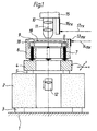
- Fig. 1 is on a base 1, a granite block 2, which is isolated by means of air springs 3 against vibrations of the base 1.
- a measuring table 4 is supported on air bearings 5 on the granite block 2.
- the measuring table 4 is horizontally displaceable in two mutually perpendicular directions, here indicated as the x and y axes.
- the drives for achieving the displacement are not shown here.
- a mirror body 6 By a mirror body 6 three bolts 7 are vertically rounded The ends are fed through without tension and protrude upwards and downwards.
- the mirror body 6 is supported on the measuring table 4 by means of the bolts 7.
- the bolts 7 are arranged so that they have a stable three-point support Effect mirror body 6 on the measuring table 4, so here two bolts on the left and at the front right in the cutting plane, the third bolt at the back in the middle.
- the lower ends of the bolts 7 designed as a spherical surface.
- the bolts 7 have a widening below the mirror body 6, which serves as a support for the mirror body 6 and when fitting the bolts 7 prevents the mirror body 6 from falling into the mirror body 6.
- the Bolts 7 are prefabricated in the example shown and subsequently in the mirror body 6 has been glued.
- the adhesive layer is not shown. Adhesives that are very hard and inelastic are suitable for the adhesive connection harden and thus deliver the most inelastic adhesive connection possible.
- the mirror body 6 consists of a material with an extremely low coefficient of expansion and is made from a single piece. So is subject to its geometry has minimal thermal fluctuations.
- Bolts 7 are also made of a material with an extremely low coefficient of expansion made, preferably from the same material as the mirror body 6. This ensures that the mirror body 6 and do not tighten the bolts 7 during thermal expansion.
- On the top At the ends of the bolts 7 there is a receptacle 8 with a frame-shaped depression in which a substrate 9 with structures 19 is placed. It is also possible, place the substrate 9 directly on the bolts 7.
- the two measuring mirrors 13 mx , 13 my (the latter is not shown) for the interferometric position determination in the x- and y-axes of the measuring table 4 are integrated in the mirror body 6. In this example, they are vapor-deposited directly onto the material of the mirror body 6.
- the integrated measuring mirrors 13 mx , 13 my are physically and thus also thermally separated from the substrate 9 and from the measuring table 4. Due to the three-point mounting of the substrate 9 or the receptacle 8 on the measuring table achieved simultaneously by means of the upper ends of the bolts 7, the weight of the substrates 9 and the receptacle 8 applied acts exclusively on the measuring table 4, but not on the mirror body 6 and the mirror geometry.
- the mirror body 6 has an edge elevation 18 on the left, the right and the side facing away from the viewer.
- a measuring mirror 13 mx for the x-axis is integrated in the mirror body 6 on the outside of the right edge elevation 18.
- An interferometer measuring beam 14 mx which is assigned to the x axis, is directed onto the measuring mirror 13 mx and is used for the interferometric determination of the x position of the measuring table 4.
- a measuring mirror 13 my (not shown here) is integrated on the outside of the rear edge elevation 18 of the mirror body 6.
- An interferometer measuring beam path 14 my (also not shown) which is assigned to the y axis and is used for the interferometric determination of the y position of the measuring table 4 is directed onto this.
- a lens 10 with an optical axis 11 is on the surface of the Substrate 9 directed. Below the substrate 9 is on the optical axis 11 a condenser 12 is slidably arranged, which can be transmitted light illumination if required generated. To enable this transmitted light illumination, are the granite block 2, the measuring table 4, the mirror body 6 and the receptacle 8 equipped with frame-shaped openings around the optical axis 11.
- a reference mirror 16 rx for the interferometric x-position determination of the measuring table 4 is attached to the stand 15 on which the objective 10 is attached. It is located at a rigid distance from the optical axis 11 of the objective 10.
- a reference mirror (16 ry ) is also attached for the interferometric position determination of the y-axis, which is not shown in this figure.
- Fig. 2 shows a measuring table 4 according to the invention with a mirror body 6 in the plan.
- the mirror body 6 is formed with an edge elevation 18 running around on three sides.
- three bolts 7 are passed through the mirror body 6 without tension and are firmly connected to it.
- a receptacle for a substrate can be placed on the bolts 7 (not shown here).
- two measuring mirrors 13 mx , 13 my are integrated in the mirror body 6, for example vapor-deposited directly onto it.
- the measuring mirror is 13 mx for an interferometer measuring beam path 14 mx for determining the position of the x-axis and the measuring mirror 13 my is arranged for an interferometer measuring beam path 14 my for determining the position of the y-axis.
- a reference mirror 16 rx or 16 ry is assigned to each interferometer measuring beam path 14 mx , 14 my . These are arranged in the vicinity and at a fixed distance from the objective 10 and its optical axis 11.
- a reference beam path 17 rx for the x-axis is directed onto the reference mirror 16 rx and a reference beam path 17 ry for the y-axis is directed onto the reference mirror 16 ry .
- the measuring table 4 is shown shifted relative to the optical axis 11. Therefore, the interferometer Meßstrahlen réelle meet 14 mx, 14, the measuring mirror 13 my mx, 13 my not in the middle but slightly offset to the side.
- the measuring mirrors 13 mx , 13 my on the outer sides of the mirror body 6 are at least as long as the maximum measuring distance in the relevant direction or as the maximum travel range of the measuring table 4 selected.
- FIG 3 shows a section through an exemplary embodiment of a measuring table 4 according to the invention, which is suitable for incident light applications and has a particularly advantageous embodiment of the bolts 7.
- a measuring table 4 which can be displaced in the x and y directions and which is supported on a granite block 2 by means of air bearings 5.
- a mirror body 6 with a laterally attached measuring mirror 13 mx for an incident interferometer measuring beam 14 mx stands on the measuring table 4 by means of three inserted bolts 7.
- the bolts each have widenings as supports 20 below the mirror body 6.
- the lower ends of the bolts 7 are equipped with a countersink 21, into each of which a ball 22 is inserted or glued.
- the right and left in the cutting plane are 4 recesses in the surface of the measuring table for receiving the Balls 22 inserted.
- the ball 22 of the left pin 7 lies in a countersink 23 in the edge area of the measuring table 4 and is thus in this position fixed.
- the ball 22 of the right bolt 7 lies in a V-groove 24 of the measuring table 4, which points in the direction of the countersink 23 and at the same time parallel to an outer edge of the measuring table 4 and thus also parallel to an outer edge of the Mirror body 6 is aligned. If the mirror body 6 as a result Slightly expand or contract thermal fluctuations should, then this ball 22 is positively guided in the V-groove 24, can however, move freely in the longitudinal direction of the V-groove. This leaves the outer edges of the mirror body 6 even with volume changes due to thermal Fluctuations always optimally parallel to the outer edges of the measuring table 4 oriented.
- the third bolt 7, which is arranged further back in the middle, is not allowed To be subjected to restraint to tension the mirror body 6 to avoid. For him, therefore, there is no recess in the measuring table 4.
- This middle bolt 7 is correspondingly somewhat shorter than the two other bolt 7 and slides on a flat sliding surface 25 of the measuring table 4th
- a special sliding surface can be used can be let into the measuring table 4, but this is not shown here.
- the Conical countersink 21, the V-groove 24 and the flat sliding surface 25 act together a stress-free, positively driven bearing, which is used in thermal Extension of the measuring table 4 or the mirror body 6 whose outer edges always keeps parallel.
- V-groove 24 and the sliding surface 25 also let conical countersinks into the surface of the measuring table 4 and the balls 22 in these three countersinks of the measuring table 4 stationary to store. Then the tension-free positive guidance at the lower ends the bolt 7 realized.
- one bolt at the bottom with one Taper countersink, a V-groove and a flat sliding surface, which itself support on the balls 22 and a stress-free, positively guided expansion ensure from measuring table 4 or mirror body 6.
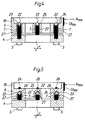
- FIG. 4 shows a section through a second exemplary embodiment of a measuring table according to the invention, which in this embodiment is suitable for both reflected light and transmitted light applications.
- a frame-shaped measuring table 4 is shown, which rests on air bearings 5.
- the upper end of the first bolt 7 has a countersink 23 on.
- the upper end of the second bolt 7 has a V-groove 24 on, the longitudinal direction of which is in line with the countersink 23.
- the upper end of the third bolt 7 has a flat sliding surface 25.
- the measuring table 4 there is a mirror body 6 with a frame-shaped opening, which has an edge elevation 18 on the left and right outside and on the back.
- a measuring mirror 13 mx is attached to the right side of the mirror body 6 for an interferometer measuring beam 14 mx measuring the x coordinate.
- the measuring mirror and the interferometer measuring beam for the y coordinate are not shown here.
- the three bolts 7 of the measuring table 4 project without jamming into three cavities 27 are vertically embedded in the underside of the mirror body 6.
- three balls 22 are fitted into the mirror body 6, e.g. sintered in.
- the balls 22 protrude upward over the top of the mirror body 6 out and down into the upper ends of the cavities 27.
- the top and bottom of the balls 22 form according to the invention the required upper and lower support points.
- the mirror body 6 supports itself by means of the underside of the balls 22 on the countersink 23, the V-groove 24 and the flat sliding surface 25 of the bolt 7, which is a stress-free Forced guidance of the ball 22 when the measuring table is thermally expanded 4 effect.
- a receptacle for a substrate or a substrate can be placed directly on the upper side of the balls 22, wherein a bracing of the mirror body 6 and an influence on the mirror geometry is excluded.
- the interferometer measuring beam 14 mx must always lie in the same plane as the structures of the substrate to be measured.
- the frame-shaped openings of the measuring table 4 and the mirror body 6 lie one above the other, so that the substrate is accessible from below and above and thus equally for incident light and transmitted light applications.
- FIG. 5 shows a section through a further exemplary embodiment of a measuring table according to the invention, which is suitable for both reflected light and transmitted light applications.
- a frame-shaped measuring table 4 is shown, which rests on air bearings 5.
- a frame-shaped mirror body 6 Arranged above the measuring table 4 is also a frame-shaped mirror body 6, which has an edge elevation 18 on the left and right outside and on the back.
- a measuring mirror 13 mx is attached for an interferometer measuring beam 14 mx measuring the x coordinate.
- the measuring mirror and the interferometer measuring beam for the y coordinate are not shown.
- the top of the first Bolt 7 has a countersink 23 and the upper end of the second bolt 7 has a V-groove 24 which points in the direction of the countersink 23 and is oriented parallel to an outer edge of the measuring table 4.
- the top end the third bolt 7 is equipped with a flat sliding surface 25.
- each Balls 22 inserted, which form the lower support points. You are lying on the countersink 23, the V-groove 24 and the flat sliding surface 25, which together a stress-free positive guidance of the balls 22 at thermal Expansion of the measuring table 4 with respect to the mirror body 6, so that the outer edges of the same are always aligned in parallel.
- the conical countersinks 28 On the surface of the mirror body 6 are above the conical countersinks 28 three hemispheres 26 applied, which form the upper support points. A receptacle for a substrate or a substrate can be placed directly on this be without tightening the mirror body 6 and thus the mirror geometry to change.
- the frame-shaped openings of the measuring table 4 and the mirror body 6 lie one above the other, the substrate is from below and above and thus equally for reflected light and transmitted light applications accessible.
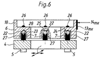
- FIG. 6 shows a section through a further exemplary embodiment of a measuring table according to the invention for incident light and transmitted light applications, which is distinguished from the exemplary embodiment in FIG. 5 by a different embodiment of the voltage-free positive guidance .
- a frame-shaped x / y-movable measuring table 4 rests on air bearings 5.
- All three bolts 7 have a countersink at their upper end 23, into each of which a ball 22 is inserted, e.g. inserted or glued, is.
- the mirror body 6 is supported, which over the Measuring table 4 is arranged.
- three cavities 27 recessed for jamming the bolts 7.
- each have a countersink 28 a V-groove 24 and a sliding surface 25 are provided.
- the V-groove 24 points in the direction the countersink 28 and is parallel to the outer edges of the Measuring table 4 and the mirror body 6 aligned.
- Hemispheres 26 formed, which form the upper support points. To this can be placed on a substrate or a holder for a substrate without to clamp the mirror body 6 and thus to change the mirror geometry.
- the frame-shaped openings of the measuring table 4 and the mirror body 6 lie one above the other, so that the substrate both from below and from above and thus equally for reflected light and transmitted light applications is accessible.
Landscapes
- Physics & Mathematics (AREA)
- General Physics & Mathematics (AREA)
- Length Measuring Devices By Optical Means (AREA)
- Details Of Measuring And Other Instruments (AREA)
Applications Claiming Priority (2)
| Application Number | Priority Date | Filing Date | Title |
|---|---|---|---|
| DE19858428 | 1998-12-17 | ||
| DE19858428A DE19858428C2 (de) | 1998-12-17 | 1998-12-17 | Koordinaten-Messanordnung |
Publications (2)
| Publication Number | Publication Date |
|---|---|
| EP1014030A1 true EP1014030A1 (fr) | 2000-06-28 |
| EP1014030B1 EP1014030B1 (fr) | 2003-06-25 |
Family
ID=7891528
Family Applications (1)
| Application Number | Title | Priority Date | Filing Date |
|---|---|---|---|
| EP99124980A Expired - Lifetime EP1014030B1 (fr) | 1998-12-17 | 1999-12-15 | Arrangement de table de mesure comprenant une table déplaçable en x/y pour détermination de coordonnées |
Country Status (6)
| Country | Link |
|---|---|
| US (1) | US6347458B1 (fr) |
| EP (1) | EP1014030B1 (fr) |
| JP (1) | JP2000180118A (fr) |
| KR (1) | KR100352187B1 (fr) |
| DE (2) | DE19858428C2 (fr) |
| TW (1) | TW544508B (fr) |
Cited By (2)
| Publication number | Priority date | Publication date | Assignee | Title |
|---|---|---|---|---|
| EP1092946A1 (fr) * | 1999-10-11 | 2001-04-18 | Leica Microsystems Wetzlar GmbH | Support de masque très précis pour mesurer l'épaisseur |
| EP1286131A1 (fr) * | 2001-08-22 | 2003-02-26 | Leica Microsystems Semiconductor GmbH | Table de mesure de coordonnées et machine de mesure de coordonnées |
Families Citing this family (41)
| Publication number | Priority date | Publication date | Assignee | Title |
|---|---|---|---|---|
| JP4434452B2 (ja) * | 2000-08-15 | 2010-03-17 | ソニーマニュファクチュアリングシステムズ株式会社 | 測尺装置 |
| DE10057036C2 (de) * | 2000-11-17 | 2002-12-12 | Basler Ag | Inspektionssystem für Flachgläser in der Displayfertigung |
| WO2002064312A1 (fr) * | 2001-02-08 | 2002-08-22 | National Aperture, Inc. | Goniometre ameliore |
| US6705019B2 (en) | 2001-02-08 | 2004-03-16 | George Mauro | Goniometer |
| US6442851B1 (en) * | 2001-05-21 | 2002-09-03 | Aerotech, Inc. | Direct drive tilt and goniometer stage |
| US7891111B2 (en) * | 2002-01-30 | 2011-02-22 | Mauro George Edward | Goniometer |
| JP2004223647A (ja) * | 2003-01-22 | 2004-08-12 | Nsk Ltd | 位置決め装置 |
| US7025498B2 (en) * | 2003-05-30 | 2006-04-11 | Asml Holding N.V. | System and method of measuring thermal expansion |
| DE102004043691B4 (de) * | 2004-09-10 | 2006-12-21 | Helios Messtechnik Gmbh & Co. Kg | Vorrichtung zum Messen der geometrischen Abmessungen und/oder der Form eines Genstandes, insbesondere eines Werkstückes |
| DE102005052758A1 (de) * | 2005-11-04 | 2007-05-16 | Leica Microsystems | Substrathalterungseinrichtung zur Verwendung in einem Positionsmessgerät |
| DE102005058504B3 (de) * | 2005-12-02 | 2007-05-16 | Zeiss Ind Messtechnik Gmbh | Vorrichtung zum Bestimmen einer Messgröße an einem Messobjekt |
| TWI302862B (en) * | 2006-05-18 | 2008-11-11 | Univ Chung Yuan Christian | Toggle-type positioning platform and toggle-type machine center |
| GB2443644B (en) * | 2006-11-09 | 2010-01-20 | Vistec Lithography Ltd | Component mounting in movement sensitive equipment |
| DE102007049133A1 (de) | 2007-02-13 | 2008-08-21 | Vistec Semiconductor Systems Gmbh | Vorrichtung zur Bestimmung der Position mindestens einer Struktur auf einem Objekt, Verwendung einer Beleuchtungseinrichtung für die Vorrichtung und Verwendung von Schutzgas für die Vorrichtung |
| US8582113B2 (en) | 2007-02-13 | 2013-11-12 | Kla-Tencor Mie Gmbh | Device for determining the position of at least one structure on an object, use of an illumination apparatus with the device and use of protective gas with the device |
| DE102007031346A1 (de) * | 2007-07-05 | 2009-01-08 | Carl Mahr Holding Gmbh | Koordinatenmessgerät mit beweglichem Portal |
| DE102007033619B4 (de) * | 2007-07-17 | 2009-12-24 | Vistec Semiconductor Systems Gmbh | Verfahren zur Ermittlung von Korrekturwerten für Messwerte der Position von Strukturen auf einem Substrat |
| DE102007035519B4 (de) * | 2007-07-26 | 2011-12-08 | Vistec Semiconductor Systems Gmbh | Verfahren zur Korrektur der aufgrund der Durchbiegung eines Substrats bedingten Messwerte |
| DE102007036815B4 (de) | 2007-08-03 | 2010-03-04 | Vistec Semiconductor Systems Gmbh | Verfahren zur Bestimmung des durch die Substrattopologie und eine Koordinaten-Messmaschine bedingten systematischen Fehlers bei der Vermesung von Positionen von Kanten von Strukturen eines Substrats |
| DE102007037705A1 (de) | 2007-08-09 | 2009-02-12 | Vistec Semiconductor Systems Jena Gmbh | Halteeinrichtung für ein zweidimensionales Substrat und Verwendung der Halteeinrichtung in einer Koordinaten-Messmaschine |
| DE102007042272B4 (de) | 2007-09-06 | 2009-09-24 | Vistec Semiconductor Systems Gmbh | Verfahren zur Korrektur der durch die Verzeichnung eines Objektivs verursachten Messfehler |
| DE102007049098A1 (de) | 2007-10-11 | 2009-04-16 | Vistec Semiconductor Systems Gmbh | Verfahren und Einrichtung zum lagerichtigen Ablegen eines Substrat in einer Koordinaten-Messmaschine |
| DE102007051391B3 (de) | 2007-10-25 | 2008-12-18 | Vistec Semiconductor Systems Gmbh | Einrichtung zum Bestimmen von Positionen von Strukturen auf einem Substrat |
| DE102007051390B4 (de) | 2007-10-25 | 2010-06-10 | Vistec Semiconductor Systems Gmbh | Verfahren zur Bestimmung der durch Relaxationsprozesse bedingten Drift eines Substrats |
| DE102007000991B4 (de) * | 2007-11-15 | 2010-07-15 | Vistec Semiconductor Systems Gmbh | Vorrichtung zur Positionsmessung mindestens einer Struktur auf einem Substrat |
| DE102008002755B4 (de) | 2008-01-24 | 2014-03-06 | Vistec Semiconductor Systems Gmbh | Verfahren zur Bestimmung eines Korrekturwerts für die Vermessung von Positionen von Strukturen auf einem Substrat |
| DE102008002770A1 (de) | 2008-02-14 | 2009-08-20 | Vistec Semiconductor Systems Gmbh | Verfahren zur Positionsbestimmung periodischer Strukturen auf einem Substrat |
| DE102008002778B4 (de) | 2008-02-21 | 2012-12-20 | Vistec Semiconductor Systems Gmbh | Verfahren zur Positionsbestimmung mindestens einer Struktur auf einem Substrat |
| DE102008002779B4 (de) | 2008-02-21 | 2010-10-07 | Vistec Semiconductor Systems Gmbh | Verfahren zum Bestimmen des Verfahrbereichs für die Fokussierung auf ein Substrat |
| DE102008002780A1 (de) | 2008-02-22 | 2009-09-10 | Vistec Semiconductor Systems Gmbh | Verfahren und Vorrichtung zum Bestimmen der zu erwartenden Lage von Strukturen auf Masken während deren Herstellung |
| CN101564820B (zh) * | 2008-04-22 | 2011-12-21 | 鸿富锦精密工业(深圳)有限公司 | 滚圆设备和滚圆方法 |
| DE102008002873A1 (de) | 2008-05-30 | 2009-12-17 | Vistec Semiconductor Systems Gmbh | Verfahren zum Auffinden eines Gebiets minimaler Lensdistortion eines Objektivs und Verwendung des Verfahrens bei einer Koordinaten-Messmaschine |
| DE102009003551A1 (de) | 2009-02-28 | 2010-09-02 | Vistec Semiconductor Systems Gmbh | Verfahren Positionsbestimmung von Strukturen auf einer Maske |
| TW201111753A (en) * | 2009-09-29 | 2011-04-01 | Everlight Electronics Co Ltd | Tilt sensor |
| DE102009044294A1 (de) | 2009-10-20 | 2011-05-05 | Kla-Tencor Mie Gmbh | Koordinatenmessmaschine zur Bestimmung der Lage von Strukturen auf einer Maske |
| DE102010000550A1 (de) | 2010-02-25 | 2011-08-25 | KLA-Tencor MIE GmbH, 35781 | Verfahren zum Fokussieren einer Objektebene und optische Anordnung |
| TWI395633B (zh) * | 2010-04-23 | 2013-05-11 | 私立中原大學 | 肘節式定位平台 |
| CN109596142A (zh) * | 2018-10-31 | 2019-04-09 | 沪东中华造船(集团)有限公司 | 水平调整工装及在舰船倾斜时惯导设备安装中的标校方法 |
| KR102840293B1 (ko) * | 2022-11-25 | 2025-07-31 | 이노로보틱스 주식회사 | 베이스 평탄 조절 조립체 |
| US20240176092A1 (en) * | 2022-11-28 | 2024-05-30 | Northrop Grumman Corporation | Optical mount assembly with adjustment mechanism having a ball bearing |
| CN118412313B (zh) * | 2024-07-01 | 2024-09-06 | 上海陛通半导体能源科技股份有限公司 | 半导体设备的对中治具及方法 |
Citations (6)
| Publication number | Priority date | Publication date | Assignee | Title |
|---|---|---|---|---|
| GB2080954A (en) * | 1980-07-31 | 1982-02-10 | Zeiss Jena Veb Carl | Attaching a measuring table to the base frame of a coordinate measuring machine |
| DE3400265A1 (de) * | 1983-01-08 | 1984-07-12 | Canon K.K., Tokio/Tokyo | Tragvorrichtung fuer praezisionsbewegungen |
| US4583847A (en) * | 1983-07-01 | 1986-04-22 | Udo Battig | Mounting table for wafers |
| US5151749A (en) * | 1989-06-08 | 1992-09-29 | Nikon Corporation | Method of and apparatus for measuring coordinate position and positioning an object |
| US5325180A (en) * | 1992-12-31 | 1994-06-28 | International Business Machines Corporation | Apparatus for identifying and distinguishing temperature and system induced measuring errors |
| EP0604380A1 (fr) * | 1992-12-22 | 1994-06-29 | C.E. Johansson Ab | Machine de mesure de coordonnées |
Family Cites Families (11)
| Publication number | Priority date | Publication date | Assignee | Title |
|---|---|---|---|---|
| US4118869A (en) * | 1977-03-02 | 1978-10-10 | Jenoptik Jena G.M.B.H. | Device for positioning an object |
| US4589746A (en) * | 1982-05-07 | 1986-05-20 | The Gerber Scientific Instrument Company | Dual-axis, single mirror interferometer measuring system |
| JPH0658410B2 (ja) * | 1986-05-23 | 1994-08-03 | 株式会社ニコン | ステ−ジ装置 |
| US4763420A (en) * | 1987-10-06 | 1988-08-16 | Brown & Sharpe Manufacturing Company | Base assembly for coordinate measuring machine |
| US4882847A (en) * | 1989-02-03 | 1989-11-28 | The Warner And Swasey Company | Coordinate measuring machine with improved carriage way arrangement |
| US5363196A (en) * | 1992-01-10 | 1994-11-08 | Ultratech Stepper, Inc. | Apparatus for measuring a departure from flatness or straightness of a nominally-plane mirror for a precision X-Y movable-stage |
| JPH08190430A (ja) * | 1995-01-12 | 1996-07-23 | Matsushita Electric Ind Co Ltd | 位置決めテーブル |
| DE29514892U1 (de) * | 1995-09-16 | 1995-11-23 | Fa. Carl Zeiss, 89518 Heidenheim | Kollisionsschutz für den Meßarm eines Koordinatenmeßgerätes |
| US6219931B1 (en) * | 1998-03-10 | 2001-04-24 | Northrop Grumman Corporation | Target base for a measuring system |
| DE19819492A1 (de) | 1998-04-30 | 1999-11-11 | Leica Microsystems | Meßgerät zur Vermessung von Strukturen auf einem transparenten Substrat |
| JP2000049066A (ja) * | 1998-07-27 | 2000-02-18 | Canon Inc | 露光装置およびデバイス製造方法 |
-
1998
- 1998-12-17 DE DE19858428A patent/DE19858428C2/de not_active Expired - Fee Related
-
1999
- 1999-12-15 DE DE59906086T patent/DE59906086D1/de not_active Expired - Lifetime
- 1999-12-15 EP EP99124980A patent/EP1014030B1/fr not_active Expired - Lifetime
- 1999-12-16 US US09/464,559 patent/US6347458B1/en not_active Expired - Lifetime
- 1999-12-16 KR KR1019990058168A patent/KR100352187B1/ko not_active Expired - Fee Related
- 1999-12-17 JP JP11359100A patent/JP2000180118A/ja not_active Withdrawn
- 1999-12-17 TW TW088122029A patent/TW544508B/zh not_active IP Right Cessation
Patent Citations (6)
| Publication number | Priority date | Publication date | Assignee | Title |
|---|---|---|---|---|
| GB2080954A (en) * | 1980-07-31 | 1982-02-10 | Zeiss Jena Veb Carl | Attaching a measuring table to the base frame of a coordinate measuring machine |
| DE3400265A1 (de) * | 1983-01-08 | 1984-07-12 | Canon K.K., Tokio/Tokyo | Tragvorrichtung fuer praezisionsbewegungen |
| US4583847A (en) * | 1983-07-01 | 1986-04-22 | Udo Battig | Mounting table for wafers |
| US5151749A (en) * | 1989-06-08 | 1992-09-29 | Nikon Corporation | Method of and apparatus for measuring coordinate position and positioning an object |
| EP0604380A1 (fr) * | 1992-12-22 | 1994-06-29 | C.E. Johansson Ab | Machine de mesure de coordonnées |
| US5325180A (en) * | 1992-12-31 | 1994-06-28 | International Business Machines Corporation | Apparatus for identifying and distinguishing temperature and system induced measuring errors |
Cited By (5)
| Publication number | Priority date | Publication date | Assignee | Title |
|---|---|---|---|---|
| EP1092946A1 (fr) * | 1999-10-11 | 2001-04-18 | Leica Microsystems Wetzlar GmbH | Support de masque très précis pour mesurer l'épaisseur |
| US6816253B1 (en) | 1999-10-11 | 2004-11-09 | Leica Microsystems Semiconductor Gmbh | Substrate holder, and use of the substrate holder in a highly accurate measuring instrument |
| US7081963B2 (en) | 1999-10-11 | 2006-07-25 | Leica Microsystems Semiconductor Gmbh | Substrate holder, and use of the substrate holder in a highly accurate measuring instrument |
| EP1286131A1 (fr) * | 2001-08-22 | 2003-02-26 | Leica Microsystems Semiconductor GmbH | Table de mesure de coordonnées et machine de mesure de coordonnées |
| US6778260B2 (en) | 2001-08-22 | 2004-08-17 | Leica Microsystems Semiconductor Gmbh | Coordinate measuring stage and coordinate measuring instrument |
Also Published As
| Publication number | Publication date |
|---|---|
| KR100352187B1 (ko) | 2002-09-12 |
| TW544508B (en) | 2003-08-01 |
| KR20000048176A (ko) | 2000-07-25 |
| DE19858428C2 (de) | 2002-09-12 |
| EP1014030B1 (fr) | 2003-06-25 |
| DE19858428A1 (de) | 2000-07-06 |
| JP2000180118A (ja) | 2000-06-30 |
| US6347458B1 (en) | 2002-02-19 |
| DE59906086D1 (de) | 2003-07-31 |
Similar Documents
| Publication | Publication Date | Title |
|---|---|---|
| EP1014030B1 (fr) | Arrangement de table de mesure comprenant une table déplaçable en x/y pour détermination de coordonnées | |
| EP1286131B1 (fr) | Table de mesure de coordonnées et machine de mesure de coordonnées | |
| AT405775B (de) | Verfahren und vorrichtung zum ausgerichteten zusammenführen von scheibenförmigen halbleitersubstraten | |
| DE4106987C2 (de) | Verfahren und Vorrichtung zum Einstellen des Spaltabstands zwischen zwei Objekten auf eine vorbestimmte Größe | |
| EP2893556B1 (fr) | Dispositif et procédé d'alignement de substrats | |
| EP3734650B1 (fr) | Procédé et dispositif d'alignement des substrats | |
| DE19949044B4 (de) | Vorrichtung zur Feinfokussierung eines Objektives in einem optischen Sytstem und Koordinaten-Messgerät mit einer Vorrichtung zur Feinfokussierung eines Objektivs | |
| DE68911330T2 (de) | Vorrichtung mit einem Ausrichtungsgestell. | |
| DE69027335T2 (de) | Servo-geführte trägertischeinrichtung | |
| DE3785090T2 (de) | Opto-lithographische Vorrichtung mit einem verstellbaren Linsensystem und Kontrollverfahren für die Abbildungseigenschaften eines Linsensystems in einer solchen Vorrichtung. | |
| EP2299472A1 (fr) | Dispositif d'alignement de deux substrats | |
| DE2942388A1 (de) | Halbleiterplaettchen-positioniervorrichtung | |
| EP3596750A1 (fr) | Procédé d'assemblage d'au moins trois substrats | |
| DE3438029A1 (de) | Roentgenstrahl-lithographieanlage | |
| DE102020210886A1 (de) | Messanordnung und Messverfahren zur Ermittlung der Position und/oder der Orientierung eines optischen Elements sowie Projektionsbelichtungsanlage | |
| DE19853588B4 (de) | Halteeinrichtung für ein Substrat | |
| WO2023110114A1 (fr) | Dispositif et procédé de réglage d'un moyen de détection | |
| DE102019203838A1 (de) | Projektionsbelichtungsanlage für die Halbleiterlithographie mit einem optischen Element mit Sensorreferenz und Verfahren zur Ausrichtung der Sensorreferenz | |
| EP2855131B1 (fr) | Procédé et dispositif de fabrication d'une pluralité de microlentilles | |
| WO1993026040A1 (fr) | Procede et dispositif pour l'empilage de substrats devant etre lies par bonding | |
| DE19853092B4 (de) | Übernahme- und Haltesystem für ein Substrat | |
| DE102017209794B4 (de) | Vorrichtung und Verfahren zur Ausrichtung eines optischen Elements, sowie Projektionsbelichtungsanlage | |
| DE19949008C2 (de) | Vorrichtung und Verfahren zum Laden von Substraten verschiedener Größe in Substrathalter | |
| DE102004010002B4 (de) | Maskenhalter zum Halten einer lithografischen Reflexionsmaske und Verfahren | |
| WO2003012548A2 (fr) | Systeme permettant le calibrage d'un systeme optique, notamment d'un objectif |
Legal Events
| Date | Code | Title | Description |
|---|---|---|---|
| PUAI | Public reference made under article 153(3) epc to a published international application that has entered the european phase |
Free format text: ORIGINAL CODE: 0009012 |
|
| AK | Designated contracting states |
Kind code of ref document: A1 Designated state(s): DE FR GB NL |
|
| AX | Request for extension of the european patent |
Free format text: AL;LT;LV;MK;RO;SI |
|
| 17P | Request for examination filed |
Effective date: 20001128 |
|
| AKX | Designation fees paid |
Free format text: DE FR GB NL |
|
| GRAH | Despatch of communication of intention to grant a patent |
Free format text: ORIGINAL CODE: EPIDOS IGRA |
|
| RTI1 | Title (correction) |
Free format text: MEASUREMENT TABLE ARRANGEMENT COMPRISING A MOVABLE X/Y STAGE FOR COORDINATE MEASUREMENT |
|
| GRAH | Despatch of communication of intention to grant a patent |
Free format text: ORIGINAL CODE: EPIDOS IGRA |
|
| GRAA | (expected) grant |
Free format text: ORIGINAL CODE: 0009210 |
|
| AK | Designated contracting states |
Designated state(s): DE FR GB NL |
|
| PG25 | Lapsed in a contracting state [announced via postgrant information from national office to epo] |
Ref country code: NL Free format text: LAPSE BECAUSE OF FAILURE TO SUBMIT A TRANSLATION OF THE DESCRIPTION OR TO PAY THE FEE WITHIN THE PRESCRIBED TIME-LIMIT Effective date: 20030625 |
|
| REG | Reference to a national code |
Ref country code: GB Ref legal event code: FG4D Free format text: NOT ENGLISH |
|
| REF | Corresponds to: |
Ref document number: 59906086 Country of ref document: DE Date of ref document: 20030731 Kind code of ref document: P |
|
| GBT | Gb: translation of ep patent filed (gb section 77(6)(a)/1977) | ||
| NLV1 | Nl: lapsed or annulled due to failure to fulfill the requirements of art. 29p and 29m of the patents act | ||
| ET | Fr: translation filed | ||
| PLBE | No opposition filed within time limit |
Free format text: ORIGINAL CODE: 0009261 |
|
| STAA | Information on the status of an ep patent application or granted ep patent |
Free format text: STATUS: NO OPPOSITION FILED WITHIN TIME LIMIT |
|
| 26N | No opposition filed |
Effective date: 20040326 |
|
| PGFP | Annual fee paid to national office [announced via postgrant information from national office to epo] |
Ref country code: GB Payment date: 20041206 Year of fee payment: 6 |
|
| PGFP | Annual fee paid to national office [announced via postgrant information from national office to epo] |
Ref country code: FR Payment date: 20041213 Year of fee payment: 6 |
|
| PG25 | Lapsed in a contracting state [announced via postgrant information from national office to epo] |
Ref country code: GB Free format text: LAPSE BECAUSE OF NON-PAYMENT OF DUE FEES Effective date: 20051215 |
|
| GBPC | Gb: european patent ceased through non-payment of renewal fee |
Effective date: 20051215 |
|
| PG25 | Lapsed in a contracting state [announced via postgrant information from national office to epo] |
Ref country code: FR Free format text: LAPSE BECAUSE OF NON-PAYMENT OF DUE FEES Effective date: 20060831 |
|
| REG | Reference to a national code |
Ref country code: FR Ref legal event code: ST Effective date: 20060831 |
|
| PGFP | Annual fee paid to national office [announced via postgrant information from national office to epo] |
Ref country code: DE Payment date: 20131230 Year of fee payment: 15 |
|
| REG | Reference to a national code |
Ref country code: DE Ref legal event code: R119 Ref document number: 59906086 Country of ref document: DE |
|
| PG25 | Lapsed in a contracting state [announced via postgrant information from national office to epo] |
Ref country code: DE Free format text: LAPSE BECAUSE OF NON-PAYMENT OF DUE FEES Effective date: 20150701 |
|
| P01 | Opt-out of the competence of the unified patent court (upc) registered |
Effective date: 20230525 |