EP1014036B2 - Dispositif et procédé pour examiner un objet - Google Patents
Dispositif et procédé pour examiner un objet Download PDFInfo
- Publication number
- EP1014036B2 EP1014036B2 EP99125794A EP99125794A EP1014036B2 EP 1014036 B2 EP1014036 B2 EP 1014036B2 EP 99125794 A EP99125794 A EP 99125794A EP 99125794 A EP99125794 A EP 99125794A EP 1014036 B2 EP1014036 B2 EP 1014036B2
- Authority
- EP
- European Patent Office
- Prior art keywords
- laser diodes
- phase
- image
- light
- interferometer
- Prior art date
- Legal status (The legal status is an assumption and is not a legal conclusion. Google has not performed a legal analysis and makes no representation as to the accuracy of the status listed.)
- Expired - Lifetime
Links
- 238000000034 method Methods 0.000 title claims abstract description 20
- 238000011156 evaluation Methods 0.000 claims description 6
- 238000003384 imaging method Methods 0.000 claims description 5
- 238000009826 distribution Methods 0.000 claims description 3
- 230000003287 optical effect Effects 0.000 claims 1
- 238000001454 recorded image Methods 0.000 claims 1
- 238000005286 illumination Methods 0.000 abstract description 9
- 230000007547 defect Effects 0.000 description 13
- 238000012360 testing method Methods 0.000 description 10
- 238000005259 measurement Methods 0.000 description 4
- 230000010363 phase shift Effects 0.000 description 4
- 238000012805 post-processing Methods 0.000 description 3
- 238000012545 processing Methods 0.000 description 3
- 230000001154 acute effect Effects 0.000 description 2
- 238000005305 interferometry Methods 0.000 description 2
- 239000011159 matrix material Substances 0.000 description 2
- 238000010008 shearing Methods 0.000 description 2
- 230000003321 amplification Effects 0.000 description 1
- 230000001427 coherent effect Effects 0.000 description 1
- 230000003247 decreasing effect Effects 0.000 description 1
- 238000001514 detection method Methods 0.000 description 1
- 238000010586 diagram Methods 0.000 description 1
- 238000006073 displacement reaction Methods 0.000 description 1
- 230000000694 effects Effects 0.000 description 1
- 238000007689 inspection Methods 0.000 description 1
- 238000011835 investigation Methods 0.000 description 1
- 238000013507 mapping Methods 0.000 description 1
- 238000003199 nucleic acid amplification method Methods 0.000 description 1
- 230000002093 peripheral effect Effects 0.000 description 1
- 230000005855 radiation Effects 0.000 description 1
- 239000007787 solid Substances 0.000 description 1
- 238000004154 testing of material Methods 0.000 description 1
- 230000009466 transformation Effects 0.000 description 1
- 238000009827 uniform distribution Methods 0.000 description 1
Images





Classifications
-
- G—PHYSICS
- G01—MEASURING; TESTING
- G01B—MEASURING LENGTH, THICKNESS OR SIMILAR LINEAR DIMENSIONS; MEASURING ANGLES; MEASURING AREAS; MEASURING IRREGULARITIES OF SURFACES OR CONTOURS
- G01B11/00—Measuring arrangements characterised by the use of optical techniques
- G01B11/16—Measuring arrangements characterised by the use of optical techniques for measuring the deformation in a solid, e.g. optical strain gauge
- G01B11/161—Measuring arrangements characterised by the use of optical techniques for measuring the deformation in a solid, e.g. optical strain gauge by interferometric means
Definitions
- the invention relates to a device and a method for examining objects.
- the invention relates to a device and a method for the investigation of deformations occurring on objects with a diffusely scattering surface.
- Non-destructive object checks are particularly interesting where quality checks on workpieces or other work objects are to be carried out. For example, in practice the task is to examine tires for defects.
- a plurality of laser diodes are used, each of which generates a light spot.
- the luminescent spots adjoin one another and at most overlap in peripheral zones.
- the illuminated partial surfaces combine the total area.
- the imaging quality of the device is limited.
- the measuring device has a plurality of laser sources which illuminate the relevant object from different spatial directions. The lighting takes place alternately. Serve arranged in the respective light paths of the two laser light sources closures, which are opened and closed alternately. From the two different illuminations ultimately two different interferometer programs are calculated, namely one for the in-plane deformation and another for the out-of-plane deformations.
- the device according to the invention has a measuring head which generates an interference image on the basis of the light backscattered by the object surface.
- An electronic image sensor which can be integrated in the measuring head, detects the interference pattern and converts it into corresponding electrical signals, which can then be further evaluated.
- the image field captured by the measuring head is illuminated by a lighting unit which has a plurality of laser diodes. These are arranged so that they form a common spot. This is uniform, illuminated, so that within the light spot only small differences in brightness can be found. This is achieved by a relatively large overlap of the light beams emerging from the individual laser diodes.
- the common spot is not subdivided into single spot spots.
- the light beams of the laser diodes can overlap so strongly that more than half of the area of the light spot receives light from two laser diodes. There is at least one area hit by the light from more than two laser diodes.
- the orientation is expediently aligned in most cases to uniform brightness distribution. It is also possible to illuminate almost the entire surface of the light spot of more than two diodes and also of different numbers of diodes.
- the laser diodes of the entire group shine simultaneously, preferably in continuous operation.
- the laser diodes can be operated pulsating. As a result, a higher light output for the moment of image acquisition is possible, which either increases the observed object field or the illumination power can be reduced or the exposure time can be shortened.
- the laser diodes it is possible to control the laser diodes in such a way or to arrange them, for example, with a shutter device such that the light of the laser diodes of the group strikes the object surface with a time offset.
- the resulting Einzelinterferogramme can be superimposed on the image sensor and summed (integrated) or, depending on the hardware, individually recorded and combined in a computer with each other. As with continuous lighting, the result is a uniformly illuminated field.
- the laser diodes can be arranged stationary or moved.
- the image sensor is preferably connected to an image evaluation device, which determines a deformation of the object surface on the basis of a plurality of recorded interference images. This is particularly useful in cases where the structure or shape of the undeformed object surface is of no interest. Such measurements are for example the workpiece or material testing appropriate. For example, they can be used to detect defects on tires. The tire surface to be examined is recorded at two different ambient pressures. Emerging deformations are made visible.
- the interferometer can work without a direct interference beam. This is possible if the beam backscattered by the object is divided into two sub-beams, one of which is subjected to a phase shift.
- the phase shift is preferably controllable or controllable.
- a device for phase shifting for example a mirror, which is adjusted by a piezoelectric actuator, is used for this purpose.
- a Michelson interferometer as the interferometer.
- a particularly advantageous embodiment uses as an interferometer, an arrangement in which the object light beam is split into two sub-beams, which arrive at different ways to the image sensor and only meet again there. This has the advantage that light losses, such as occur in the Michelson interferometer when merging the partial beams in the beam splitter are avoided.
- the image sensor is connected to an image evaluation device, which preferably has a computing unit.
- the arithmetic unit for example, a correspondingly powerful computer, executes a program that accomplishes the image processing.
- a phase image is calculated from a plurality of images recorded by the stationary object with phase shift shifted relative to one another.
- the phase positions of individual pixels are usually stochastically distributed and give no direct information about the object. If, however, the object surface is deformed or displaced by a small amount toward or away from the measuring head, and a phase image is obtained in this state, for example by linking a plurality of interferences which have been changed by phase shifting, a phase difference image can be determined from the two phase images obtained.
- the phase difference image provides information about local displacements or deformations and can be displayed.
- a gray value is assigned to the respective phase difference angle of the pixel, which is displayed on a reproduction device at the relevant point.
- a phase difference angle of zero the display value is black and the phase difference angle of 2 ⁇ gray value assigned to white.
- the phase difference angles, before they are displayed 2 ⁇ / n-modulated.
- the difference angles of the phase difference image are subjected point by point to a modulo 2 ⁇ / n division.
- This result value is multiplied by the factor n and gives the 2 ⁇ / n-modulated value, which is displayed in the value range from zero to 2 ⁇ / n with gray values between black and white.
- a colored display can also be selected.
- the factor n is preferably an integer greater than 1. This results in an amplification of the existing and visible in the phase difference image object deformations, and thus a clearer recognizability of defects on the object.
- n the higher the resolution, i. the more stripes account for a given object deformation.
- the operator it is expedient for the operator to be able to select the factor n by means of suitable input means.
- the factor may also be switched after image acquisition to perform the same test run, i. to represent the same object deformation with different modulations.
- the method is suitable for test objects with a diffusely scattering surface and gives a pictorial representation of phase difference angles. This allows the operator to easily detect structural errors in the measured object. In this case, this method is applicable for any test objects or error sizes and requires a low computational effort, so that the result representation is guaranteed virtually in real time.
- the value to be displayed is scaled so that the displayable gray value range of the image processing system is fully utilized.
- the greyscale value or color value corresponding to an angle of zero size can be interactively set by the user.
- the 2 ⁇ / n-modulated phase difference image can also be obtained directly from the phase-shifted intensity images of a first series of images in a first object state and a second series of phase-shifted images (intensity images) in a second state of the object.
- the equations for 2 ⁇ / n modulation are used in the equations for generating the phase difference images from the intensity images.
- all points of the luminous spot which are detected by the camera or another image capture device, are illuminated by at least two laser diodes.
- Fig. 1 is a measuring system for deformation measurement on a test object 1 by means of shearing interferometry shown.
- a lighting unit E which has a plurality of laser diodes 2, 3.
- Fig. 2 In this case, the illumination of the surface of the test object 1 is illustrated in more detail.
- the schematically illustrated illumination unit E has, in addition to the laser diodes 2, 3 further laser diodes 4, 5, 6, each of which generates a light cone 2a, 3a, 4a, 5a, 6a.
- the light cones 2a,..., 6a flow into one another, so that they overlap one another several times on the object surface 1.
- a light spot 7 which is largely uniformly illuminated.
- An arbitrarily selected location S is illuminated by a plurality of light cones 4a, 5a, 6a, which can have the same or different opening angles.
- the light of the respective laser diode 4, 5, 6 has substantially the same wavelength, but is not coherent with each other. The same applies to the backscattered light.
- a measuring head 8 which is connected to an image evaluation unit 9.
- image evaluation unit 9 include a computer 10 and a monitor 11 and an input device, such as a keyboard 12.
- the measuring head 8 contains an interferometer 14 which receives light radiation backscattered by the object surface via an objective 15.
- a light spot 7 which is formed of a plurality of mutually strongly overlapping partial luminous spots 7a, 7b, 7c, 7d, 7f, 7g, 7h, 7i.
- Parts of the light spot 7 are illuminated by up to four different laser diodes.
- the beam fanning can also be made larger, so that each laser diode almost illuminates the same spot 7.
- the illumination can be made from different solid angles out, so that there is a uniform distribution of scattered light in the room and a uniform spot illumination.
- the objective 15 has an aperture angle ⁇ with which the object surface is recorded. In this case, the arrangement is preferably made such that the light spot 7 fills the field of view of the objective 15 relatively precisely. If necessary, however, deviations may also be present.
- the objective 15 preferably includes an aperture and a subjacent lens system 17 for forming a light beam from the light backscattered from the object surface. This is fed to a beam splitter 18 which is arranged in the beam path of the lens system 17.
- the beam splitter 18 splits the incoming light beam into two partial beams which strike the mirrors 19, 20 almost at right angles. These are arranged so that they reflect the respective partial light beam substantially back into itself, whereby a certain tilting is permitted or necessary for the generation of shearing mappings.
- the mirror 19 is mounted stationary, while the mirror 20 by a, for example Fig. 1 apparent piezoelectric drive device is adjustable in and against the beam direction.
- the piezoactuator is controlled by the computer 10 and adapted to adjust the mirror, based on the wavelength of light, for example in ⁇ / 4-steps.
- the beam splitter 18 merges the partial beams reflected by the mirrors 19, 20 back together and to a camera 24 via an imaging objective 23.
- the camera 24 contains as image sensor, a CCD matrix 25 and the corresponding electronic components for controlling the same.
- the camera 24 is with the Computer 10 connected.
- the object 1 is placed in front of the measuring head 8 and illuminated with the laser diodes 2, 3, 4, 5, 6.
- the laser diodes 2, 3, 4, 5, 6 can be operated in continuous operation, i. shine constantly at the same time.
- the light spot 7 is thereby generated, which falls on the area to be examined for defects.
- several images are now taken of the object surface. For this purpose, given a given positioning of the mirrors 19, 20, first a first image is taken and stored.
- the image captured by the image sensor 25 is an object surface interference pattern containing stochastically distributed light, dark, and gray areas called "speckles."
- the computer controls the mirror 20 so that it is shifted by a known amount. This results in a defined phase shift between the two partial beams of the mirrors 19 and 20.
- the speckle image changes thereby, as the individual speckles assume changed brightness. The speckle, however, remain in the same place.
- the computer 10 calculates the phase angle valid for each speckle or pixel.
- the object 1 to be tested is subjected to a test force, for example. In the case of tires this can be done by changing the ambient pressure. This results in the surface of the object 1 characteristic deformations that are greater in particular at flaws than the deformation of the environment.
- a plurality of speckle images phase-shifted by adjusting the mirror 20 are recorded again, from which the changed phase angles are then calculated pixel-by-pixel. This results in a second phase angle image.
- a phase difference image is now generated from the two phase images obtained. This is done pixel by pixel or pixel by pixel. The phase angle difference between deformed and undeformed state is determined for each pixel. If the phase difference image is obtained in this way, it can be displayed on the monitor 11.
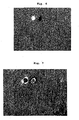
- a defect image generated by this method is shown in Fig. 6 played. While a black-appearing flaw is still relatively well visible, the left flank next to it seems to be relatively weak.
- FIG. 5 This operation is in Fig. 5 illustrated.
- the diagram illustrates the assignment of a gray value G to a phase difference angle ⁇ at a selected point x, y.
- phase difference angle values between zero and 2 ⁇ gray values corresponding to a straight line 30 are assigned.
- the existing phase difference angle ⁇ for example 3 ⁇ / 4
- the remaining division value is ⁇ / 4 and represents the result of the modulo 2 ⁇ / 4 division.
- n is the factor which characterizes the increase in the straight line 31 compared to the straight line 30.
- the difference gray angle ⁇ / 4 is assigned the same gray value as the difference angles 3 ⁇ / 4, 1 1/4 ⁇ and 1 3/4 ⁇ .
- the resulting monitor image is in Fig. 7 illustrated. The two defects are clearly highlighted as a bright or dark spot. This allows a safe and accurate representation of defects and avoids the danger of being at the inspection of the object will be overlooked structural errors due to blurred appearance.
- phase difference angle ⁇ or the 2 ⁇ / n-modulated difference angle ⁇ as an argument in a sine function to perform a sine transform. This must be done point by point.
- the transformation is: ⁇ x y ⁇ sin ⁇ x y ,
- the amplitude of the interference lines is normalized, ie the amplitude of the sine modulation is constant everywhere in the picture regardless of the location. The result is a good readable image, especially flaw image ( Fig. 8 ).
- the number of interference lines also increases with increasing n.
- the image processing device 9, i. the program running on the computer 10 may be such that the choice of the modulation is possible, for example by input of the factor n.
- the program may be such that between playback, the phase difference angle (with and without modulation) and the playback of a sinustransform Being image can be switched.
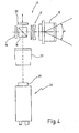
- Fig. 1 is based on a measuring head 8 with Michelson interferometer.
- a measuring head 8 can be used with an interferometer 14, in which a light beam is split into partial beams A, B, which are first combined at the CCD matrix 25 to form an interference pattern.
- the interferometer 14 has a recording lens 41, which directs a light beam onto a beam splitter 42.
- the partial beams A and B are formed.
- the partial beam A is forwarded to a tilting mirror 43 and deflected approximately at right angles.
- the partial beam B initially strikes a mirror 44 which is displaceably mounted with a drive, for example a piezo drive, in order to be reflected at an acute angle.
- a measuring system is used in particular for the detection of defects on test objects.
- the measurement object 1 is uniformly illuminated from a lighting unit E which contains a plurality of laser diodes 2, 3, 4, 5, 6.
- the beam cones of the individual lasers overlap strongly, which provides homogeneous illumination even with large exposure angles and changing imaging ratios due to different object sizes and distances.
- the measuring object 1 is observed interferometrically. From individual images phase difference images are determined. These are 2 ⁇ / n-modulated, which in particular in the range of defects phase jumps arise, which give particularly good contrasts.
Landscapes
- Physics & Mathematics (AREA)
- General Physics & Mathematics (AREA)
- Investigating Materials By The Use Of Optical Means Adapted For Particular Applications (AREA)
- Length Measuring Devices By Optical Means (AREA)
- Instruments For Measurement Of Length By Optical Means (AREA)
- Analysing Materials By The Use Of Radiation (AREA)
Claims (24)
- Dispositif pour déterminer des déformations de la surface d'un objet à tester, en particulier d'une surface émettant un rayonnement diffus, comprenant
Une unité d'éclairage (E) comportant un groupe de diodes laser (2, 3, 4, 5, 6) qui chacune produit un cône lumineux (2a, 3a, 4a, 5a, 6a);
Une tête de mesure (8) comportant un interféromètre (14), l'interféromètre (14) générant une image d'interférence a partir de la lumière reflétée par la surface de l'objet à tester;
Un capteur d'image électronique (25) monté sur le parcours des rayons de l'interféromètre (14) de sorte que l'image d'interférence est saisie par le capteur d'image (25);
les diodes laser (2, 3, 4, 5, 6) étant arrangées de telle manière, que les cônes lumineux (2a, 3a, 4a, 5a) s'écoulent l'un dans l'autre et se chevauchent à plusieurs reprises sur la surface de l'objet à tester et produisent simultanément une tache lumineuse (7) commune avec une répartition régulière de la luminosité sur la surface de l'objet à tester, et qui présente au moins une zone qui est illuminée d'au moins deux diodes laser (2, 3, 4, 5, 6). - Dispositif selon la revendication 1, caractérisé en ce que la tache lumineuse (7) présente plusieurs zones, qui sont éclairées par la lumière émise par plus de deux diodes laser.
- Dispositif selon la revendication 1, caractérisé en ce que les diodes laser (2, 3, 4, 5, 6) éclairent en continu.
- Dispositif selon la revendication 1, caractérisé en ce que les diodes laser (2, 3, 4, 5, 6) fonctionnent de manière pulsatoire.
- Dispositif selon la revendication 1, caractérisé en ce que chaque point de la tache lumineuse (7) qui se trouve dans la zone de ladite tache (7) saisie par le capteur d'image (25) est éclairé par au moins deux diodes laser (2, 3, 4, 5, 6).
- Dispositif selon la revendication 1, caractérisé en ce que le capteur d'image (25) est relié à un dispositif de traitement d'images (9) qui détermine, à partir de plusieurs images d'interférence prises, une déformation de la surface de l'objet.
- Dispositif selon la revendication 1, caractérisé en ce que l'interféromètre (14) présente un dispositif (20, 21) pour produire le déphasage relatif de deux rayonnements partiels.
- Dispositif selon la revendication 6, caractérisé en ce que le dispositif de traitement d'images (9) comprend une unité de calcul (10) conçue pour calculer une image de phase à partir de plusieurs images de l'objet prises dans diverses positions de phase.
- Dispositif selon la revendication 8, caractérisé en ce que l'unité de calcul (10) es conçue pour, à partir d'au moins deux images de phase différentes prises de préférence dans des états différents de l'objet, déterminer une image différentielle de phase Δϕ(x, y), l'angle de phase ϕ1(x, y) d'un point d'image (x, y) associé à un premier état de l'objet étant soustrait d'un second angle de phase ϕ2(x, y) du même point d'image (x, y) associé à un second état de l'objet.
- Dispositif selon la revendication 9, caractérisé en ce que l'unité de calcul (10) divise point par point les valeurs de différences de phase par un modulo 2π/n, multiplie le résultat par un facteur n et met à disposition la valeur obtenue.
- Dispositif selon la revendication 10, caractérisé en ce que n est un nombre entier supérieur ou égal à 1.
- Dispositif selon l'une des revendications 9 à 11, caractérisé en ce que l'unité de calcul (10) introduit point d'image par point d'image, en tant qu'argument dans une fonction sinus, les différences de phase Δϕ(x, y) ou les valeurs modulées par 2-π/n et met à disposition la valeur obtenue.
- Dispositif selon l'une des revendications 8 à 12, caractérisé en ce que l'unité de calcul (10) est reliée à un dispositif d'affichage (11) et que la valeur mise à disposition est représentée par le dispositif d'affichage (11).
- Dispositif selon la revendication 1, caractérisé en ce que l'interféromètre (14) est du type Michelson.
- Dispositif selon la revendication 1, caractérisé en ce que l'interféromètre (14) comprend un diviseur de rayonnement (18) qui divise la lumière venant de la surface de l'objet en deux rayonnements partiels que suivent des parcours différents pour venir frapper le capteur d'images (25) afin de produire une figure d'interférence.
- Procédé pour déterminer des déformations de la surface d'un objet à tester, en particulier d'une surface émettant un rayonnement diffus, par les moyens d'une observation ou d'une image interférométrique de cette surface, comprenant les étapes de procédé suivantes:a) La surface de l'objet à tester est illuminé par des diodes laser (2, 3, 4, 5, 6) qui chacune produit un cône lumineux (2a, 3a, 4a, 5a, 6a);b) La lumière des diodes laser (2, 3, 4 , 5, 6) est guidée sur une tache lumineuse (7) commune sur l'objet à tester, les diodes laser (2, 3, 4, 5, 6) étant arrangées de telle manière, que les cônes lumineux (2a, 3a, 4a, 5a) s'écoulent l'un dans l'autre et se chevauchent à plusieurs reprises sur la surface de l'objet à tester pour produire simultanément une tache lumineuse (7) commune avec une répartition régulière de la luminosité sur la surface de l'objet à tester, et qui présente au moins une zone qui est illuminée d'au moins deux diodes laser (2, 3, 4, 5, 6).c) une image d'interférence est générée par superposition des interférogrammes simples résultants, à partir de la lumière reflétée par la surface de l'objet à tester.
- Procédé selon la revendication 16, caractérisé en ce que la tache lumineuse (7) présente plusieurs zones, qui sont éclairées par la lumière émise par plus de deux diodes laser.
- Procédé selon la revendication 16, caractérisé en ce que les diodes laser (2, 3, 4, 5, 6) du groupe éclairent en même temps, et de préférence en continu.
- Procédé selon la revendication 16, caractérisé en ce que les diodes laser (2, 3, 4, 5, 6) du groupe fonctionnent de manière pulsatoire.
- Procédé selon la revendication 16, caractérisé en ce que
à partir de plusieurs images prises avec déphasage entre elles de la surface de l'objet dans un seul et même état, on obtient des images de phase ϕ(x, y) et
à partir d'au moins deux images de phase (ϕ1(x, y), (ϕ2(x, y)) différentes prises de préférence dans des états différents de l'objet, on définit une image différentielle de phase Δϕ(x, y), l'angle de phase Δϕ1(x, y) d'un point d'image (x, y), associé à un premier état de l'objet, étant soustrait de l'angle de phase Δϕ2(x, y) du même point d'image (x, y) associé à un second état de l'objet. - Procédé selon la revendication 20, caractérisé en ce que
les valeurs de différences de phase sont divisées point par point par 2π/n, (n ε N, n ≥ 1)
le reste est multiplié par un facteur n, et
le résultat est mis à disposition en tant que valeur modulée par 2n/n. - Procédé selon la revendication 20, caractérisé en ce qu'à partir d'images d'intensité prises avec déphasage, on tire directement une image à différentielle de phase modulée par 2π/n.
- Procédé selon l'une des revendications 20 à 22, caractérisé en ce que les différences de phase Δϕ(x, y) ou les valeurs modulées par 2π/n sont introduites pour chaque point d'image en tant qu'argument dans une fonction sinus, et la valeur obtenue est mise à disposition.
- Procédé selon l'une des revendications 21 à 23, caractérisé en ce que la valeur mise à disposition est représentée par un dispositif d'affichage (11).
Priority Applications (1)
| Application Number | Priority Date | Filing Date | Title |
|---|---|---|---|
| DE29924939U DE29924939U1 (de) | 1998-12-23 | 1999-12-23 | Vorrichtung zur Objektuntersuchung |
Applications Claiming Priority (2)
| Application Number | Priority Date | Filing Date | Title |
|---|---|---|---|
| DE19859725A DE19859725C2 (de) | 1998-12-23 | 1998-12-23 | Vorrichtung zur Ermittlung von Verformungen an einer Objektoberfläche, insbesondere einer diffus streuenden Objektoberfläche und Verwendung der Vorichtung |
| DE19859725 | 1998-12-23 |
Publications (4)
| Publication Number | Publication Date |
|---|---|
| EP1014036A2 EP1014036A2 (fr) | 2000-06-28 |
| EP1014036A3 EP1014036A3 (fr) | 2002-05-02 |
| EP1014036B1 EP1014036B1 (fr) | 2004-01-07 |
| EP1014036B2 true EP1014036B2 (fr) | 2010-04-21 |
Family
ID=7892434
Family Applications (1)
| Application Number | Title | Priority Date | Filing Date |
|---|---|---|---|
| EP99125794A Expired - Lifetime EP1014036B2 (fr) | 1998-12-23 | 1999-12-23 | Dispositif et procédé pour examiner un objet |
Country Status (4)
| Country | Link |
|---|---|
| US (1) | US6417916B1 (fr) |
| EP (1) | EP1014036B2 (fr) |
| AT (1) | ATE257582T1 (fr) |
| DE (2) | DE19859725C2 (fr) |
Families Citing this family (32)
| Publication number | Priority date | Publication date | Assignee | Title |
|---|---|---|---|---|
| US6717681B1 (en) * | 1999-03-31 | 2004-04-06 | Benjamin A. Bard | Portable real-time high-resolution digital phase-stepping shearography with integrated excitation mechanisms |
| EP1215465A1 (fr) | 2000-11-29 | 2002-06-19 | Steinbichler Optotechnik Gmbh | Procédé et appareil pour mesurer la déformation d'objets |
| DE10101057B4 (de) * | 2000-11-29 | 2004-01-15 | Steinbichler Optotechnik Gmbh | Verfahren und Vorrichtung zur Erfassung der Verformung von Objekten |
| EP1333260A3 (fr) * | 2002-01-31 | 2004-02-25 | Canon Kabushiki Kaisha | Procédé et dispositif de mesure de phase |
| US7310139B2 (en) * | 2002-03-28 | 2007-12-18 | Takai Tofu & Soymilk Equipment Company Limited | Evaluation method and device for gel state or sol-gel state change of object |
| JP2004271381A (ja) * | 2003-03-10 | 2004-09-30 | Fuji Photo Optical Co Ltd | スペックル干渉計装置 |
| DE10319099B4 (de) * | 2003-04-28 | 2005-09-08 | Steinbichler Optotechnik Gmbh | Verfahren zur Interferenzmessung eines Objektes, insbesondere eines Reifens |
| JP2005134196A (ja) * | 2003-10-29 | 2005-05-26 | Nec Electronics Corp | 非破壊解析方法及び非破壊解析装置 |
| DE10354582A1 (de) * | 2003-11-21 | 2005-06-30 | Hentze-Lissotschenko Patentverwaltungs Gmbh & Co.Kg | Anordnung und Verfahren zur Unterdrückung von Speckle-Strukturen eines gepulsten Laserstrahles |
| US7474297B2 (en) * | 2004-03-22 | 2009-01-06 | Avago Technologies Ecbu Ip (Singapore) Pte. | Contaminant-resistant optical mouse and cradle |
| US7423765B2 (en) * | 2004-07-31 | 2008-09-09 | Carl Zeiss Smt Ag | Optical system of a microlithographic projection exposure apparatus |
| US7791727B2 (en) | 2004-08-16 | 2010-09-07 | Asml Netherlands B.V. | Method and apparatus for angular-resolved spectroscopic lithography characterization |
| US20080144036A1 (en) * | 2006-12-19 | 2008-06-19 | Asml Netherlands B.V. | Method of measurement, an inspection apparatus and a lithographic apparatus |
| DE102005032735B3 (de) * | 2005-06-16 | 2007-02-22 | Mähner, Bernward | Vorrichtung und Verfahren zum Prüfen eines Reifens |
| DE102005049607A1 (de) * | 2005-10-17 | 2007-04-19 | Steinbichler Optotechnik Gmbh | Verfahren und Vorrichtung zur Erfassung der Verformung von Objekten |
| US7492450B2 (en) * | 2005-10-24 | 2009-02-17 | General Electric Company | Methods and apparatus for inspecting an object |
| DE102006014070B4 (de) | 2006-03-27 | 2008-02-07 | Mähner, Bernward | Vorrichtung und Verfahren zum Prüfen eines Reifens, insbesondere mittels eines interferometrischen Messverfahrens |
| DE102006014058B4 (de) * | 2006-03-27 | 2008-04-17 | Mähner, Bernward | Vorrichtung und Verfahren zum optischen Prüfen eines Reifens |
| DE102006015123B4 (de) | 2006-03-31 | 2008-03-20 | Mähner, Bernward | Vorrichtung und Verfahren zum Prüfen eines Reifens, insbesondere mittels eines interferometrischen Messverfahrens |
| DE102006061003B4 (de) | 2006-12-22 | 2009-03-26 | Mähner, Bernward | Vorrichtung zum Prüfen eines Prüfobjekts, insbesondere eines Reifens, mittels eines zerstörungsfreien Messverfahrens |
| DE102007009040C5 (de) | 2007-02-16 | 2013-05-08 | Bernward Mähner | Vorrichtung und Verfahren zum Prüfen eines Reifens, insbesondere mittels eines interferometrischen Messverfahrens |
| DE102007031774A1 (de) | 2007-07-07 | 2009-01-15 | Mähner, Bernward | Verfahren und Vorrichtung zur Vermessung von Objekten mittels hochdynamischer Bildaufnahmen |
| DE102007040353B3 (de) * | 2007-08-27 | 2009-04-23 | Mähner, Bernward | Vorrichtung zum Prüfen eines Prüfobjekts, insbesondere eines Reifens, mittels eines zerstörungsfreien Messverfahrens |
| DE102008037356C5 (de) | 2008-08-12 | 2020-09-17 | Bernward Mähner | Stapelmodul und Zentriermodul für eine Prüfanlage zum Prüfen von Reifen |
| DE102013102296B4 (de) | 2012-12-21 | 2018-11-08 | Bernward Mähner | Vorrichtung und Verfahren zum Prüfen eines Reifens mittels eines interferometrischen Messverfahrens |
| DE102013010402A1 (de) | 2013-06-21 | 2014-12-24 | Steinbichler Optotechnik Gmbh | Reifenprüfgerät, Reifenprüfanlage und Verfahren zur Reifenprüfung |
| JP2016040541A (ja) * | 2014-08-13 | 2016-03-24 | ソニー株式会社 | 信号処理装置、信号処理方法、並びにプログラム |
| DE102018001255A1 (de) | 2018-02-18 | 2019-08-22 | Bernward Mähner | Verfahren und Vorrichtung zur Untersuchung von rotationssymmetrischen Prüfobjekten |
| US10962419B2 (en) * | 2019-04-09 | 2021-03-30 | Carl Zeiss Optotechnik GmbH | Method for testing a tire by interferometry |
| EP4416459B1 (fr) | 2021-10-12 | 2024-12-04 | Dengler, Stefan | Procédé de test de pneumatiques |
| DE102022126613A1 (de) | 2022-10-12 | 2024-04-18 | Stefan Dengler | Verfahren zum Prüfen von Reifen |
| DE102023132675B3 (de) | 2023-11-23 | 2024-12-24 | Stefan Dengler | Vorrichtung und Verfahren zum Prüfen eines Reifens, insbesondere mittels eines interferometrischen Messverfahrens |
Citations (1)
| Publication number | Priority date | Publication date | Assignee | Title |
|---|---|---|---|---|
| DE4231578C2 (de) † | 1992-09-21 | 1995-06-29 | Nova C O R D Ag | Verfahren zur Ermittlung von Verformungen an einem Prüfobjekt mit diffus streuender Oberfläche, insbesondere an Reifen, sowie Vorrichtung zur Durchführung des Verfahrens |
Family Cites Families (7)
| Publication number | Priority date | Publication date | Assignee | Title |
|---|---|---|---|---|
| IT1135701B (it) * | 1981-03-23 | 1986-08-27 | Cise Spa | Apparecchiatura per la rivelazione degli spostamenti di punti di strutture eccitate |
| DE4013309A1 (de) * | 1990-04-26 | 1991-10-31 | Zeiss Carl Fa | Verfahren und anordnung zur optischen untersuchung von prueflingen |
| DE4102881A1 (de) * | 1991-01-31 | 1992-08-06 | Man Technologie Gmbh | Verfahren und vorrichtung zur erfassung der oberflaechendeformation mittels speckle-interferometrie |
| JP3414417B2 (ja) * | 1992-09-30 | 2003-06-09 | 富士通株式会社 | 立体画像情報伝送システム |
| DE4446887A1 (de) * | 1994-12-28 | 1996-07-04 | Wolfgang Prof Dr Ing Steinchen | Verfahren und Vorrichtung für die Shearing-Speckle-Interferometrie |
| DE19501073A1 (de) * | 1995-01-16 | 1996-08-01 | Nova C O R D Ag | Bildverarbeitungsverfahren zur Ermittlung der Strukturfestigkeit eines Prüfobjektes mit diffus streuender Oberfläche |
| US6043870A (en) * | 1996-07-01 | 2000-03-28 | Cybernet Systems Corporation | Compact fiber optic electronic laser speckle pattern interferometer |
-
1998
- 1998-12-23 DE DE19859725A patent/DE19859725C2/de not_active Expired - Fee Related
-
1999
- 1999-12-23 AT AT99125794T patent/ATE257582T1/de not_active IP Right Cessation
- 1999-12-23 EP EP99125794A patent/EP1014036B2/fr not_active Expired - Lifetime
- 1999-12-23 DE DE59908245T patent/DE59908245D1/de not_active Expired - Lifetime
-
2000
- 2000-05-09 US US09/566,727 patent/US6417916B1/en not_active Expired - Lifetime
Patent Citations (1)
| Publication number | Priority date | Publication date | Assignee | Title |
|---|---|---|---|---|
| DE4231578C2 (de) † | 1992-09-21 | 1995-06-29 | Nova C O R D Ag | Verfahren zur Ermittlung von Verformungen an einem Prüfobjekt mit diffus streuender Oberfläche, insbesondere an Reifen, sowie Vorrichtung zur Durchführung des Verfahrens |
Non-Patent Citations (3)
| Title |
|---|
| BISLE W.J.: "Optische Prüfung an Luftfahrtkomponenten: Weiterentwicklung des Scherografie-Prüfverfahrens für Nicht-Kooperative Oberflächen von Flugzeugstrukturen", DGLR JAHRESTAGUNG, DEUTSCHER LUFT- UND RAUMFAHRTKONGRESS 1998, 5 October 1998 (1998-10-05) - 8 October 1998 (1998-10-08), BREMEN † |
| STEINCHEN WOLFGANG ET AL: "Application of Laser Diodes in Digital Speckle Pattern Shearing Interferometry", vol. 3415, July 1998, QUEBEC, CANADA, article "SPIE Conference on Laser Diodes and Applications III" † |
| YANG, LIANGXIANG: "Fortschrittsberichte VDI Reihe 8", vol. 682, 1998, VDI VERLAG, DÜSSELDORF, article "Grundlagen und Anwendungen der Phasenschiebe-Shearografie zur zerstörungsfreien Werkstoffprüfung, Dehnungsmessung und Schwingungsanalyse" † |
Also Published As
| Publication number | Publication date |
|---|---|
| EP1014036B1 (fr) | 2004-01-07 |
| EP1014036A2 (fr) | 2000-06-28 |
| EP1014036A3 (fr) | 2002-05-02 |
| DE19859725A1 (de) | 2000-07-06 |
| US6417916B1 (en) | 2002-07-09 |
| DE59908245D1 (de) | 2004-02-12 |
| DE19859725C2 (de) | 2001-02-22 |
| ATE257582T1 (de) | 2004-01-15 |
Similar Documents
| Publication | Publication Date | Title |
|---|---|---|
| EP1014036B1 (fr) | Dispositif et procédé pour examiner un objet | |
| DE4231578C2 (de) | Verfahren zur Ermittlung von Verformungen an einem Prüfobjekt mit diffus streuender Oberfläche, insbesondere an Reifen, sowie Vorrichtung zur Durchführung des Verfahrens | |
| DE102014108789B4 (de) | Mehrstufiges Verfahren zur Untersuchung von Oberflächen sowie entsprechende Vorrichtung | |
| DE102017009099B4 (de) | Phasenverschiebungs-interferometer und formmessverfahren | |
| DE10242373B4 (de) | Konfokaler Abstandssensor | |
| DE19613677A1 (de) | Verfahren und Vorrichtung zum Erfassen des Oberflächenprofils eines Objektes | |
| EP1284409A1 (fr) | Procédé et appareil pour l'inspection de la déformation d'objets | |
| DE19859801C2 (de) | Verfahren zur echtzeitfähigen Ermittlung und Darstellung von Verformungen oder Verschiebungen von Prüfobjekten und Vorrichtung zur Durchführung des Verfahrens | |
| DE19929406A1 (de) | Zeilen-OCT als optischer Sensor für die Meß- und Medizintechnik | |
| DE102010037207B3 (de) | Rauheits-Messvorrichtung und -Messverfahren | |
| EP1030161B1 (fr) | Image à différence de phase avec filtrage passe bas et déplacement des valeurs grises | |
| EP1775548B1 (fr) | Procédé et dispositif pour la détection de la déformation d'objets. | |
| DE3020044C2 (fr) | ||
| DE10101057B4 (de) | Verfahren und Vorrichtung zur Erfassung der Verformung von Objekten | |
| DE19513233C2 (de) | Verfahren und Vorrichtung zur Bestimmung von Phasen und Phasendifferenzen | |
| DE29924939U1 (de) | Vorrichtung zur Objektuntersuchung | |
| DE29924968U1 (de) | Vorrichtung zur Objektuntersuchung | |
| DE29924967U1 (de) | Vorrichtung zur Objektuntersuchung | |
| EP1239261B1 (fr) | Appareil et procédé d'examen pour objets déformables | |
| DE19716785A1 (de) | Shearing-Speckle-Interferometrie III: Shearing-Speckle-Interferometrie zur Messung der Verformungsgradienten an Freiformflächen | |
| DE102010029627A1 (de) | Vorrichtung und Verfahren zur Bestimmung der Struktur einer spiegelnden Oberfläche eines Objekts | |
| DE19521551C2 (de) | Speckle-Interferometrie-Verfahren zur Gewinnung topographischer Informationen von einer konstanten Objektoberfläche | |
| EP1012534B1 (fr) | Procede et dispositif pour la determination de deformations et d'allongements sur des corps curvilignes | |
| DE69218558T2 (de) | Berührungsloses Verfahren und Vorrichtung zur Höhendifferenzmessung von zwei Oberflächen | |
| DE19625830A1 (de) | Verfahren und Vorrichtung für die Shearing-Speckle-Interferometrie |
Legal Events
| Date | Code | Title | Description |
|---|---|---|---|
| PUAI | Public reference made under article 153(3) epc to a published international application that has entered the european phase |
Free format text: ORIGINAL CODE: 0009012 |
|
| AK | Designated contracting states |
Kind code of ref document: A2 Designated state(s): AT BE CH CY DE DK ES FI FR GB GR IE IT LI LU MC NL PT SE Kind code of ref document: A2 Designated state(s): AT DE FR GB IT |
|
| AX | Request for extension of the european patent |
Free format text: AL;LT;LV;MK;RO;SI |
|
| RAP1 | Party data changed (applicant data changed or rights of an application transferred) |
Owner name: MAEHNER, BERNWARD Owner name: DENGLER, STEFAN |
|
| RIN1 | Information on inventor provided before grant (corrected) |
Inventor name: MAEHNER, BERNWARD Inventor name: DENGLER, STEFAN |
|
| PUAL | Search report despatched |
Free format text: ORIGINAL CODE: 0009013 |
|
| AK | Designated contracting states |
Kind code of ref document: A3 Designated state(s): AT BE CH CY DE DK ES FI FR GB GR IE IT LI LU MC NL PT SE |
|
| AX | Request for extension of the european patent |
Free format text: AL;LT;LV;MK;RO;SI |
|
| RIC1 | Information provided on ipc code assigned before grant |
Free format text: 7G 01B 11/16 A, 7G 01M 17/02 B |
|
| 17P | Request for examination filed |
Effective date: 20021015 |
|
| 17Q | First examination report despatched |
Effective date: 20021127 |
|
| AKX | Designation fees paid |
Free format text: AT DE FR GB IT |
|
| GRAP | Despatch of communication of intention to grant a patent |
Free format text: ORIGINAL CODE: EPIDOSNIGR1 |
|
| GRAS | Grant fee paid |
Free format text: ORIGINAL CODE: EPIDOSNIGR3 |
|
| GRAA | (expected) grant |
Free format text: ORIGINAL CODE: 0009210 |
|
| AK | Designated contracting states |
Kind code of ref document: B1 Designated state(s): AT DE FR GB IT |
|
| REG | Reference to a national code |
Ref country code: GB Ref legal event code: FG4D Free format text: NOT ENGLISH |
|
| REG | Reference to a national code |
Ref country code: IE Ref legal event code: FG4D Free format text: GERMAN |
|
| REF | Corresponds to: |
Ref document number: 59908245 Country of ref document: DE Date of ref document: 20040212 Kind code of ref document: P |
|
| GBT | Gb: translation of ep patent filed (gb section 77(6)(a)/1977) |
Effective date: 20040318 |
|
| REG | Reference to a national code |
Ref country code: IE Ref legal event code: FD4D |
|
| ET | Fr: translation filed | ||
| PLBQ | Unpublished change to opponent data |
Free format text: ORIGINAL CODE: EPIDOS OPPO |
|
| PLBI | Opposition filed |
Free format text: ORIGINAL CODE: 0009260 |
|
| PLAX | Notice of opposition and request to file observation + time limit sent |
Free format text: ORIGINAL CODE: EPIDOSNOBS2 |
|
| 26 | Opposition filed |
Opponent name: STEINBICHLER OPTOTECHNIK GMBH Effective date: 20041007 |
|
| PLAX | Notice of opposition and request to file observation + time limit sent |
Free format text: ORIGINAL CODE: EPIDOSNOBS2 |
|
| PLBB | Reply of patent proprietor to notice(s) of opposition received |
Free format text: ORIGINAL CODE: EPIDOSNOBS3 |
|
| RAP2 | Party data changed (patent owner data changed or rights of a patent transferred) |
Owner name: MAEHNER, BERNWARD Owner name: DENGLER, STEFAN |
|
| RIN2 | Information on inventor provided after grant (corrected) |
Inventor name: MAEHNER, BERNWARD Inventor name: DENGLER, STEFAN |
|
| APBP | Date of receipt of notice of appeal recorded |
Free format text: ORIGINAL CODE: EPIDOSNNOA2O |
|
| APAH | Appeal reference modified |
Free format text: ORIGINAL CODE: EPIDOSCREFNO |
|
| APBQ | Date of receipt of statement of grounds of appeal recorded |
Free format text: ORIGINAL CODE: EPIDOSNNOA3O |
|
| APBP | Date of receipt of notice of appeal recorded |
Free format text: ORIGINAL CODE: EPIDOSNNOA2O |
|
| APBQ | Date of receipt of statement of grounds of appeal recorded |
Free format text: ORIGINAL CODE: EPIDOSNNOA3O |
|
| PGFP | Annual fee paid to national office [announced via postgrant information from national office to epo] |
Ref country code: AT Payment date: 20081218 Year of fee payment: 10 |
|
| PLBP | Opposition withdrawn |
Free format text: ORIGINAL CODE: 0009264 |
|
| APBU | Appeal procedure closed |
Free format text: ORIGINAL CODE: EPIDOSNNOA9O |
|
| PLAB | Opposition data, opponent's data or that of the opponent's representative modified |
Free format text: ORIGINAL CODE: 0009299OPPO |
|
| PUAH | Patent maintained in amended form |
Free format text: ORIGINAL CODE: 0009272 |
|
| STAA | Information on the status of an ep patent application or granted ep patent |
Free format text: STATUS: PATENT MAINTAINED AS AMENDED |
|
| 27A | Patent maintained in amended form |
Effective date: 20100421 |
|
| AK | Designated contracting states |
Kind code of ref document: B2 Designated state(s): AT DE FR GB IT |
|
| PG25 | Lapsed in a contracting state [announced via postgrant information from national office to epo] |
Ref country code: AT Free format text: LAPSE BECAUSE OF NON-PAYMENT OF DUE FEES Effective date: 20091223 |
|
| REG | Reference to a national code |
Ref country code: DE Ref legal event code: R008 Ref document number: 59908245 Country of ref document: DE |
|
| REG | Reference to a national code |
Ref country code: DE Ref legal event code: R039 Ref document number: 59908245 Country of ref document: DE Effective date: 20130404 |
|
| PGFP | Annual fee paid to national office [announced via postgrant information from national office to epo] |
Ref country code: GB Payment date: 20141216 Year of fee payment: 16 |
|
| REG | Reference to a national code |
Ref country code: DE Ref legal event code: R097 Ref document number: 59908245 Country of ref document: DE Ref country code: DE Ref legal event code: R040 Ref document number: 59908245 Country of ref document: DE |
|
| REG | Reference to a national code |
Ref country code: FR Ref legal event code: PLFP Year of fee payment: 17 |
|
| GBPC | Gb: european patent ceased through non-payment of renewal fee |
Effective date: 20151223 |
|
| PG25 | Lapsed in a contracting state [announced via postgrant information from national office to epo] |
Ref country code: GB Free format text: LAPSE BECAUSE OF NON-PAYMENT OF DUE FEES Effective date: 20151223 |
|
| REG | Reference to a national code |
Ref country code: FR Ref legal event code: PLFP Year of fee payment: 18 |
|
| REG | Reference to a national code |
Ref country code: FR Ref legal event code: PLFP Year of fee payment: 19 |
|
| PGFP | Annual fee paid to national office [announced via postgrant information from national office to epo] |
Ref country code: FR Payment date: 20171219 Year of fee payment: 19 |
|
| PGFP | Annual fee paid to national office [announced via postgrant information from national office to epo] |
Ref country code: IT Payment date: 20171218 Year of fee payment: 19 |
|
| PGFP | Annual fee paid to national office [announced via postgrant information from national office to epo] |
Ref country code: DE Payment date: 20180125 Year of fee payment: 19 |
|
| REG | Reference to a national code |
Ref country code: DE Ref legal event code: R119 Ref document number: 59908245 Country of ref document: DE |
|
| PG25 | Lapsed in a contracting state [announced via postgrant information from national office to epo] |
Ref country code: FR Free format text: LAPSE BECAUSE OF NON-PAYMENT OF DUE FEES Effective date: 20181231 Ref country code: DE Free format text: LAPSE BECAUSE OF NON-PAYMENT OF DUE FEES Effective date: 20190702 Ref country code: IT Free format text: LAPSE BECAUSE OF NON-PAYMENT OF DUE FEES Effective date: 20181223 |