EP1014055A2 - Gerät zur Farbmessung mit einer mit mehreren Protokollen versehenen Schnittstelle - Google Patents
Gerät zur Farbmessung mit einer mit mehreren Protokollen versehenen Schnittstelle Download PDFInfo
- Publication number
- EP1014055A2 EP1014055A2 EP99310394A EP99310394A EP1014055A2 EP 1014055 A2 EP1014055 A2 EP 1014055A2 EP 99310394 A EP99310394 A EP 99310394A EP 99310394 A EP99310394 A EP 99310394A EP 1014055 A2 EP1014055 A2 EP 1014055A2
- Authority
- EP
- European Patent Office
- Prior art keywords
- pin
- connector
- cable
- outs
- color measurement
- Prior art date
- Legal status (The legal status is an assumption and is not a legal conclusion. Google has not performed a legal analysis and makes no representation as to the accuracy of the status listed.)
- Withdrawn
Links
Images


Classifications
-
- G—PHYSICS
- G01—MEASURING; TESTING
- G01J—MEASUREMENT OF INTENSITY, VELOCITY, SPECTRAL CONTENT, POLARISATION, PHASE OR PULSE CHARACTERISTICS OF INFRARED, VISIBLE OR ULTRAVIOLET LIGHT; COLORIMETRY; RADIATION PYROMETRY
- G01J3/00—Spectrometry; Spectrophotometry; Monochromators; Measuring colours
- G01J3/02—Details
- G01J3/0264—Electrical interface; User interface
-
- G—PHYSICS
- G01—MEASURING; TESTING
- G01J—MEASUREMENT OF INTENSITY, VELOCITY, SPECTRAL CONTENT, POLARISATION, PHASE OR PULSE CHARACTERISTICS OF INFRARED, VISIBLE OR ULTRAVIOLET LIGHT; COLORIMETRY; RADIATION PYROMETRY
- G01J3/00—Spectrometry; Spectrophotometry; Monochromators; Measuring colours
- G01J3/02—Details
- G01J3/0272—Handheld
-
- G—PHYSICS
- G01—MEASURING; TESTING
- G01J—MEASUREMENT OF INTENSITY, VELOCITY, SPECTRAL CONTENT, POLARISATION, PHASE OR PULSE CHARACTERISTICS OF INFRARED, VISIBLE OR ULTRAVIOLET LIGHT; COLORIMETRY; RADIATION PYROMETRY
- G01J3/00—Spectrometry; Spectrophotometry; Monochromators; Measuring colours
- G01J3/46—Measurement of colour; Colour measuring devices, e.g. colorimeters
- G01J3/50—Measurement of colour; Colour measuring devices, e.g. colorimeters using electric radiation detectors
Definitions
- the present invention relates to color measurement instruments, and more particularly to color measurement instruments capable of communicating in multiple protocols.
- Color measurement instruments are capable of reading a color for the subsequent conversion of the color to a mathematical representation. That representation can be processed using techniques known to those skilled in the art to perform color functions such as calibration.
- Color measurement instruments include, by way of illustration and not limitation, spectrophotometers, colorimeters, densitometers, and spectroradiometers.
- One particularly useful color measurement instrument is a monitor colorimeter (also known as a colorimetric radiometer) manufactured and sold by X-Rite Incorporated (X-Rite) of Grandville, Michigan as Model No. DTP92Q.
- This colorimeter is a tethered desktop unit for monitor calibration, and it includes a handheld unit and a cord for connecting the unit to the serial port of a computer.
- the handheld unit can be positioned over a portion of a monitor screen to read the color displayed on that portion of the screen.
- the color information or representation is communicated to the computer through the cord.
- the communication protocol for the colorimeter is RS232.
- the color information received by the computer from the colorimeter can be processed using color management software such as that sold by X-Rite under the trademark COLOR SHOP or that sold by Apple Computer under the trademark COLORSYNC.
- USBIF Universal Serial Bus Implementers Forum
- Apple Computer is phasing out the inclusion of RS232 serial ports on new computers.
- a unit such as the DTP92Q which is capable of communicating only in the RS232 protocol, is not compatible with the USB protocol. Additional future changes in communications protocols are anticipated. For example, one such protocol is known as Fire Wire. Accordingly, it is possible that a colorimeter redesigned for the USB protocol may itself be outdated shortly.
- a color measurement instrument is capable of multiple communication protocols each associated with a unique interface cable.
- the implemented protocol is selected by connecting the appropriate cable to the handheld unit - either during manufacture or during subsequent service.
- the color measurement instrument includes on-board hardware, firmware, and/or software capable of communicating in a variety of protocols through a common internal connector. Any one of a variety of cables may be connected to the connector. Each of the cables is uniquely associated with a particular communication protocol and includes a connector interfitting with the connector within the instrument. Appropriate connections are made between the cable connector pin-outs and the on-board connector pin-outs so that the instrument communicates though the cable in the selected protocol.
- the instrument is capable of communicating in both the RS232 protocol and the USB protocol.
- a first cable is unique to the RS232 protocol, and a second cable is unique to the USB protocol.
- Either cable may be connected to the instrument, and particularly to the internal connector. After a particular cable has been connected, the instrument communicates in the selected protocol through the cable.
- the present invention is not restricted to the particular protocols disclosed.
- the invention is readily extendable to other exiting protocols and to future communication protocols.
- the present invention provides improved flexibility for color measurement instruments.
- the instrument is “generic" to all protocols. Only the cable varies by instrument to implement a desired protocol.
- the "generic" design of the instrument simplifies manufacture, testing, and calibration. During manufacture, the instrument can be tested and calibrated using any one of the available protocols.
- a color measurement instrument constructed in accordance with a preferred embodiment of the invention is illustrated in Figs. 1 and 2 and generally designated 10.
- the instrument 10 is a monitor colorimeter (also known as a colorimetric radiometer).
- the invention is considered to encompass any color measurement instrument including, but not limited to, spectrophotometers, colorimeters, densitometers, and spectroradiometers.
- the instrument 10 includes a handheld unit 12 and a cable or cord 14.
- the handheld unit is capable of communicating in multiple communication protocols. Any particular cable 14 is unique to a particular communication protocol.
- the cable illustrated in Figs. 1-3 is adapted for communication in the Universal Serial Bus (USB) protocol.
- USB Universal Serial Bus
- the handheld unit 12 is generally well known to those skilled in the art.
- one similar unit has been sold by X-Rite as a monitor colorimeter under the model designation DTP92Q. Accordingly, this description will focus on the new invention related to the multiple communication protocol capability.
- the hardware of the handheld unit 12 is schematically illustrated in Fig. 4.
- the prior art components within that handheld unit include a microcontroller 20, a program memory 22, a data memory 24, photodiodes 26, an A/D (analog to digital) converter 28, and a voltage regulator 30. Accordingly, these components will be described only briefly.
- the microcontroller 20 provides overall control for the unit 12. More specifically, the microcontroller 20 receives digital input from the photodiodes 26 through the A/D converter 28 and converts those signals to coordinates in a color space. The acquired data is stored in the data memory 24.
- the firmware or software program control is stored in the program memory 22.
- the voltage regulator 30 provides internal regulated power to the unit 12.
- the new components within the handheld unit 12 include the ten-pin connector 40, the USB interface chip 42, and the associated electrical connections. These components are commercially available, but are uniquely used within the present instrument as part of the present invention.
- the USB interface chip 42 operates within the USB protocol. More specifically, the chip 42 defines four subsets of the USB protocol and is capable of communicating within any one of those subsets. The present invention utilizes only the "bulk transfer" subset, but other subsets could be used in its place.
- the interconnection/interface of the USB chip 42 with the microcontroller 20 is well known to those skilled in the art. Alternatively, the microprocessor 20 and the USB interface could be incorporated into a single chip, and such chips are commercially available. Other implementations will be recognized by those skilled in the art.
- the connector 40 (Figs. 3-4) is an in-line, ten-pin connector conventional in the art. Other connectors, both known and developed in the future, could also be readily used to implement the present invention.
- Fig. 4 illustrates the pin-outs of the ten-pin connector. Pin 1 is connected to the input voltage (+VIN). Pins 2, 8, and 10 are commonly connected to ground (GND). Pin 3 is connected to the microcontroller 20 via the RS232 transfer data (TXD) line 31a, and pin 4 is connected to the microcontroller 20 via the RS232 receive data line (RXD) 31b.
- TXD transfer data
- RXD receive data line
- Pin 7 is connected to the USB chip 42 via the USB data high (USBD+) line 43a
- pin 9 is connected to the USB chip 42 via the USB data low (USBD-) line 43b.
- Pins 5 and 6 are "spares" that are not assigned.
- the USB cable 14 (Figs. 1-3 and 5) includes a USB connector 50, a strain relief 52, and a ten-pin connector 54 (see Fig. 3).
- the USB cable 14 includes at least four wires/connections to communicate in the USB protocol.
- the USB connector 50 is known to those skilled in the art and is suited for insertion into a USB socket S, for example in the front of monitor M as illustrated in Fig. 1.
- the strain relief 52 is also well known to those skilled in the art and reduces strain on the cable 14 where it passes through and is connected to the unit 12. See Fig. 3.
- pins 1-4 of the USB connector 50 are connected to pins 1, 9, 7, and 2, respectively, of the ten-pin connector 54. Accordingly, pin 1 of the ten-pin connector provides an input voltage; pin 2 provides a ground; pin 7 provides data high; and pin 9 provides data low.
- the ten-pin connector 54 of the cable 14 can be physically connected to the ten-pin connector 40 of the unit 12.
- the pin-outs 1-10 of the connector 54 are connected to the associated pin-outs 1-10 of the connector 40.
- the voltage regulator is operatively connected to the input voltage (+VIN); the grounds (GND) are connected; and the data lines (USBD+ and USBD-) are connected through lines 43a and b to the USB interface chip 42.
- the unit 12 therefore receives appropriate power and is grounded.
- the microcontroller is capable of communicating in the USB protocol through the chip 42.
- the RS232 cable 14' is illustrated in Fig. 5 and includes a power connector 50', an RS232 connector 50", and a ten-pin connector 54'. All three connectors are of a type known to those skilled in the art. Pins 1 and 2 of the power connector 50' are electrically connected to pins 1 and 8 of the 10-pin connector 54'. Pins 2, 3, and 5 of the RS 232 connector 50" are electrically connected to pins 3, 4, and 2 of the connector 54'. Accordingly, the input voltage (+VIN) is supplied to pin 1 of the connector 54'; ground (GND) is applied to pins 2 and 8; and data lines (TXD and RXD) are applied to pins 3 and 4.
- a single cable having both types of connectors -- one for each protocol -- connected thereto could be used. In such case, only one of the connectors would be connected to the instrument at any given time; and the necessary pin-outs for both protocols would be included in the single cable.
- Fig. 4 All of the electrical components schematically illustrated in Fig. 4 are mounted within the handheld unit 12 and are connected to each other using techniques customary in the art.
- the ten-pin connector 40 is available within the unit 12 for connection to one of the cables 14 or 14'.
- the connector 40 could be located so as to be accessible from outside of the housing 13. Such a construction would enable the ultimate consumer and/or user of the instrument 10 to readily and easily change the cable connected to the unit, and thereby change the communication protocol. In any of the implementations, it is possible that the instrument 10 will obtain all of its power requirements (in all modes of the instrument and in all protocols) through the connected cable.
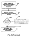
- the prior art software/firmware of the prior art unit is illustrated in Figs. 7-8. This software/firmware is carried into the present instrument 10.
- the serial communication subroutine is illustrated in Fig. 7 and is executed 700 each time that the microcontroller 20 receives an interrupt signal indicating that an RS232 character must be processed.
- the received character is stored 701 in the next available character in the RCI (Remote Control Interface) buffer. If 702 the byte is a carriage return, then the executive functions subroutine (see Fig. 8) is notified 703 that a complete command string has been received. If 702 the byte is anything other than a carriage return, then the interrupt subroutine is exited 704.
- the RS232 serial communication occurs character by character.
- Fig. 8 The prior art software/firmware for the executive functions subroutine is illustrated in Fig. 8. This software/firmware is carried forward into, and supplemented in, the present instrument 10. All of the "other processing" of the unit 10 is illustrated as box 801.
- the serial communication subroutine (Fig. 7) indicates that a complete RCI string has been received 802, control passes to box 803. If 802 a complete RCI command string has not been received, control returns to the other processing 801.
- box 803 the last two characters of the command string are separated from the remainder of the string. The last two characters specify the command to be performed, and the remainder of the string contains the parameters to the command.
- the command characters are CF, a configuration function is executed 804. If the command characters are BR, a band rate function is executed 805.
- command characters are RM
- a read monitor function is executed 806.
- other commands generically designated XX will cause other functions to be executed 807.
- a response is sent 808 to the host computer indicating that the command has been processed and transferring any data that may have been requested by the host computer.
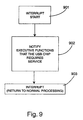
- Fig. 9 illustrates the USB interrupt routine which is new to the instrument 10.
- the routine starts 901 when an interrupt signal is received from the USB interface chip 42 (see Fig. 4). USB communication occurs in packets rather than character by character. An interrupt request is issued by the USB interface chip 42 only when a complete packet, comprising a complete command, has been received by the USB chip 42.
- the executive functions routine is notified 902 that the USB chip requires service. Program flow then returns 903 to the other processing.
- the executive functions subroutine of the present instrument 10 is illustrated in Fig. 10.
- the portions of the executive functions subroutine outside of the dashed line 810 is identical to the executive functions subroutine of the prior art illustrated in Fig. 8.
- the boxes 1001 to 1008 of Fig. 10 correspond to boxes 801-808 of Fig. 8. Accordingly, the program flow and operation illustrated in those boxes will not be re-described.
- the portion of the executive function subroutine within the dashed line 810 is specific to the USB interface and provides a second communication protocol.
- program flow passes to block 1011. If 1011 the USB chip 42 requires service, data is read 1012 from the chip; and program flow passes to box 1013. If 1011 the USB chip 42 does not require service, program flow passes to box 1002 for the function previously described.
- USB packet The type of USB packet is determined 1013. If the packet is a data packet, the data packet is copied 1014 into the command string; and control passes to the previously described block 1003. If the packet is a control packet, the USB-specific control information is processed 1015; and program flow returns to the other processing 1001.
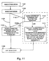
- the send-string routine is illustrated in Fig. 11 and is utilized to send information out of the unit 12 through the connector 40.
- the prior art portion of the send-string routine is outside of dashed line 1101; and the new portion of the send-string routine is inside the dashed line 1101.
- program flow line 1105 of the prior art function is replaced by program flow lines 1112 and 1113. Accordingly, program flow cannot pass directly from block 1103 to block 1104.
- program flow passes to block 1110.
- the blocks 1110 and 1111 additionally check for and handle USB transmissions. If 1110 the source is RS232, program flow passes to block 1104.
- 1110 the command is a USB command, program flow passes to block 1111.
- the character is collected 1111 in the USB output buffer, and program flow passes to block 1106 wherein the send character-function is terminated.
- the entire string is collected in the USB chip 42 before the string is transmitted to the host computer in response to a request from the host computer.
- the unit 10 of the present invention is capable of communicating with a host computer using one of a plurality of communication protocols.
- the present invention has been described in conjunction with the RS232 and USB protocols, the invention is not so limited. Any current or future communication protocol could be used in implementing the present invention. Also, although the present invention has been described in conjunction with two protocols, any number could be implemented by a routine extension of the disclosed methodology.
- the individual protocol that an instrument 10 will use is determined by the cable 14 or 14' connected to the handheld unit 12. As illustrated in Figs. 4-6, the appropriate pin-out connections are made as the connectors cable connector 54 or 54' is physically interconnected with the unit connector 40. The microcontroller 20 and the USB chip 42 are automatically and appropriately connected to the cable to implement the desired communication protocol.
Landscapes
- Physics & Mathematics (AREA)
- Spectroscopy & Molecular Physics (AREA)
- General Physics & Mathematics (AREA)
- Engineering & Computer Science (AREA)
- Human Computer Interaction (AREA)
- Arrangements For Transmission Of Measured Signals (AREA)
- Spectrometry And Color Measurement (AREA)
- Information Transfer Systems (AREA)
Applications Claiming Priority (4)
| Application Number | Priority Date | Filing Date | Title |
|---|---|---|---|
| US11375498P | 1998-12-23 | 1998-12-23 | |
| US113754P | 1998-12-23 | ||
| US411484 | 1999-10-01 | ||
| US09/411,484 US6493084B1 (en) | 1998-12-23 | 1999-10-01 | Color measurement instrument with multiple protocol interface |
Publications (2)
| Publication Number | Publication Date |
|---|---|
| EP1014055A2 true EP1014055A2 (de) | 2000-06-28 |
| EP1014055A3 EP1014055A3 (de) | 2000-12-27 |
Family
ID=26811429
Family Applications (1)
| Application Number | Title | Priority Date | Filing Date |
|---|---|---|---|
| EP99310394A Withdrawn EP1014055A3 (de) | 1998-12-23 | 1999-12-22 | Gerät zur Farbmessung mit einer mit mehreren Protokollen versehenen Schnittstelle |
Country Status (2)
| Country | Link |
|---|---|
| US (1) | US6493084B1 (de) |
| EP (1) | EP1014055A3 (de) |
Cited By (5)
| Publication number | Priority date | Publication date | Assignee | Title |
|---|---|---|---|---|
| GB2351576A (en) * | 1999-01-28 | 2001-01-03 | Hewlett Packard Co | Providing protocols to a connector |
| EP1484708A3 (de) * | 2003-06-04 | 2009-04-29 | STMicroelectronics, Inc. | Multimode Chip-Karten-Emulator |
| CN102735342A (zh) * | 2011-04-01 | 2012-10-17 | 爱色丽欧洲公司 | 手持式颜色测量装置 |
| CN108760051A (zh) * | 2018-05-07 | 2018-11-06 | 链尚信息科技(上海)有限公司 | 取色方法、信息处理方法、设备及计算机可读存储介质 |
| CN112099108A (zh) * | 2020-09-09 | 2020-12-18 | 中国海洋石油集团有限公司 | 一种plt仪器的连接装置 |
Families Citing this family (11)
| Publication number | Priority date | Publication date | Assignee | Title |
|---|---|---|---|---|
| EP1067369B1 (de) * | 1999-07-06 | 2009-12-09 | X-Rite Europe GmbH | Lichtmessvorrichtung |
| US6691201B1 (en) * | 2000-06-21 | 2004-02-10 | Cypress Semiconductor Corp. | Dual mode USB-PS/2 device |
| DE10047321A1 (de) * | 2000-09-25 | 2002-04-25 | Grieshaber Vega Kg | Verfahren zum Anzeigen und/oder Ändern von Parametern einer Messvorrichtung und Messvorrichtung zur Durchführung des Verfahrens |
| US7376734B2 (en) * | 2002-02-14 | 2008-05-20 | Panduit Corp. | VOIP telephone location system |
| US7689724B1 (en) | 2002-08-16 | 2010-03-30 | Cypress Semiconductor Corporation | Apparatus, system and method for sharing data from a device between multiple computers |
| US7293118B1 (en) | 2002-09-27 | 2007-11-06 | Cypress Semiconductor Corporation | Apparatus and method for dynamically providing hub or host operations |
| US20050116942A1 (en) * | 2003-09-26 | 2005-06-02 | Vander Jagt Peter G. | Color measurement instrument |
| US7653123B1 (en) | 2004-09-24 | 2010-01-26 | Cypress Semiconductor Corporation | Dynamic data rate using multiplicative PN-codes |
| JP4463658B2 (ja) * | 2004-10-28 | 2010-05-19 | 日本電産サンキョー株式会社 | 情報処理システムの下位装置、下位装置用動作制御プログラムおよび下位装置用動作制御方法 |
| DE202016008478U1 (de) * | 2015-06-30 | 2018-03-22 | Opple Lighting Co. Ltd. | Vorrichtung zur Erfassung und Analyse von Umgebungslicht |
| BR112021011320A2 (pt) * | 2019-12-27 | 2022-09-13 | Basf Coatings Gmbh | Servidor, sistema e método para controlar qualidade de cor, e, meio de armazenamento legível por computador |
Family Cites Families (11)
| Publication number | Priority date | Publication date | Assignee | Title |
|---|---|---|---|---|
| US4591978A (en) | 1983-11-14 | 1986-05-27 | Foresight Enterprises Inc. | Method of interrelating a master computer with a peripheral device |
| DE3347326A1 (de) | 1983-12-23 | 1985-07-18 | LMT Lichtmeßtechnik GmbH Berlin & Co Gerätebau KG, 1000 Berlin | Geraeteeigene einrichtung zur pruefung von farbmesskoepfen |
| EP0523308A1 (de) | 1991-07-19 | 1993-01-20 | GRETAG Aktiengesellschaft | Fotometrisches Verfahren und computergesteuertes Fotometer |
| GB2258125A (en) | 1991-07-20 | 1993-01-27 | Ibm | Improved method and apparatus for setting the colour balance of a colour display device |
| US5400138A (en) | 1992-11-20 | 1995-03-21 | X-Rite, Incorporated | Programmable spectrophotometer using a data memory for storing a sequence of generalized commands |
| GB2302489A (en) | 1995-06-15 | 1997-01-15 | Ibm | Computer monitor with user-selectable communication protocol |
| US5706816A (en) * | 1995-07-17 | 1998-01-13 | Aloka Co., Ltd. | Image processing apparatus and image processing method for use in the image processing apparatus |
| US5860924A (en) * | 1996-11-26 | 1999-01-19 | Advanced Technology Laboratories, Inc. | Three dimensional ultrasonic diagnostic image rendering from tissue and flow images |
| US5876342A (en) * | 1997-06-30 | 1999-03-02 | Siemens Medical Systems, Inc. | System and method for 3-D ultrasound imaging and motion estimation |
| EP0913674A1 (de) * | 1997-10-31 | 1999-05-06 | Gretag-Macbeth AG | Rechnergesteuerte Messvorrichtung |
| JP4260920B2 (ja) * | 1998-05-13 | 2009-04-30 | 株式会社東芝 | 超音波診断装置 |
-
1999
- 1999-10-01 US US09/411,484 patent/US6493084B1/en not_active Expired - Fee Related
- 1999-12-22 EP EP99310394A patent/EP1014055A3/de not_active Withdrawn
Cited By (9)
| Publication number | Priority date | Publication date | Assignee | Title |
|---|---|---|---|---|
| GB2351576A (en) * | 1999-01-28 | 2001-01-03 | Hewlett Packard Co | Providing protocols to a connector |
| US6334160B1 (en) | 1999-01-28 | 2001-12-25 | Hewlett-Packard Co. | Apparatus and method for providing multiple protocols through a common connector in a device |
| GB2351576B (en) * | 1999-01-28 | 2004-02-11 | Hewlett Packard Co | Apparatus for multiplexing serial signals onto a parallel bus |
| EP1484708A3 (de) * | 2003-06-04 | 2009-04-29 | STMicroelectronics, Inc. | Multimode Chip-Karten-Emulator |
| CN102735342A (zh) * | 2011-04-01 | 2012-10-17 | 爱色丽欧洲公司 | 手持式颜色测量装置 |
| CN102735342B (zh) * | 2011-04-01 | 2016-08-03 | 爱色丽瑞士有限公司 | 手持式颜色测量装置 |
| CN108760051A (zh) * | 2018-05-07 | 2018-11-06 | 链尚信息科技(上海)有限公司 | 取色方法、信息处理方法、设备及计算机可读存储介质 |
| CN112099108A (zh) * | 2020-09-09 | 2020-12-18 | 中国海洋石油集团有限公司 | 一种plt仪器的连接装置 |
| CN112099108B (zh) * | 2020-09-09 | 2024-04-09 | 中国海洋石油集团有限公司 | 一种plt仪器的连接装置 |
Also Published As
| Publication number | Publication date |
|---|---|
| US6493084B1 (en) | 2002-12-10 |
| EP1014055A3 (de) | 2000-12-27 |
Similar Documents
| Publication | Publication Date | Title |
|---|---|---|
| US6493084B1 (en) | Color measurement instrument with multiple protocol interface | |
| US6738856B1 (en) | External display peripheral for coupling to a universal serial bus port or hub on a computer | |
| US6898660B2 (en) | System for extending length of a connection to a USB device | |
| US5668419A (en) | Reconfigurable connector | |
| US8176226B2 (en) | KVMP switch allowing asynchronous and synchronous switching for console devices and peripheral devices among different computers | |
| CN106463877B (zh) | 插拔连接器系统 | |
| US5918194A (en) | Integrated modular measurement system having configurable firmware architecture and modular mechanical parts | |
| AU2007240183B2 (en) | Apparatus for managing multiple computers with a cartridge connector | |
| TWI235910B (en) | Apparatus for testing I/O ports of a computer motherboard | |
| US5293497A (en) | Cable for transmitting eight-bit parallel data | |
| JPS63153677A (ja) | 最近似色合せ装置 | |
| JPH11201818A (ja) | プロセッサ制御の測定装置 | |
| CA2690212A1 (en) | Analyte test instrument system including data management system | |
| US20050262279A1 (en) | USB OTG adapter module for debugging USB OTG devices | |
| US20070165277A1 (en) | Point-of-sale demonstration of computer peripherals | |
| WO2008021638A2 (en) | Rs-232 data through a half duplex differential link | |
| CA2329883A1 (en) | Backward compatible diagnostic tool | |
| JPH0830306A (ja) | 制御装置 | |
| US20060149863A1 (en) | System for extending length of a connection to a USB device | |
| CA2393577A1 (en) | Measurement module and system for monitoring the status of armored vehicle electronic components | |
| KR100239119B1 (ko) | 피씨와 통신하는 모니터 | |
| US7873873B2 (en) | Remote access integrated tester | |
| CN115237697B (zh) | 一种通用型密码机测试平台 | |
| US5598543A (en) | Method of interfacing between data transmission systems having an unequal number of transceiver ports | |
| CN206595011U (zh) | 一种智能led显示屏系统 |
Legal Events
| Date | Code | Title | Description |
|---|---|---|---|
| PUAI | Public reference made under article 153(3) epc to a published international application that has entered the european phase |
Free format text: ORIGINAL CODE: 0009012 |
|
| AK | Designated contracting states |
Kind code of ref document: A2 Designated state(s): DE FR GB |
|
| AX | Request for extension of the european patent |
Free format text: AL;LT;LV;MK;RO;SI |
|
| PUAL | Search report despatched |
Free format text: ORIGINAL CODE: 0009013 |
|
| AK | Designated contracting states |
Kind code of ref document: A3 Designated state(s): AT BE CH CY DE DK ES FI FR GB GR IE IT LI LU MC NL PT SE |
|
| AX | Request for extension of the european patent |
Free format text: AL;LT;LV;MK;RO;SI |
|
| 17P | Request for examination filed |
Effective date: 20010611 |
|
| AKX | Designation fees paid |
Free format text: DE FR GB |
|
| 17Q | First examination report despatched |
Effective date: 20031127 |
|
| STAA | Information on the status of an ep patent application or granted ep patent |
Free format text: STATUS: THE APPLICATION HAS BEEN WITHDRAWN |
|
| 18W | Application withdrawn |
Effective date: 20090219 |