EP1014063B1 - Kraftaufnehmer - Google Patents
KraftaufnehmerInfo
- Publication number
- EP1014063B1 EP1014063B1 EP99250411A EP99250411A EP1014063B1 EP 1014063 B1 EP1014063 B1 EP 1014063B1 EP 99250411 A EP99250411 A EP 99250411A EP 99250411 A EP99250411 A EP 99250411A EP 1014063 B1 EP1014063 B1 EP 1014063B1
- Authority
- EP
- European Patent Office
- Prior art keywords
- force
- longitudinal
- tensile force
- transverse
- link
- Prior art date
- Legal status (The legal status is an assumption and is not a legal conclusion. Google has not performed a legal analysis and makes no representation as to the accuracy of the status listed.)
- Expired - Lifetime
Links
- 230000001419 dependent effect Effects 0.000 claims description 3
- 239000000523 sample Substances 0.000 abstract description 3
- 230000006835 compression Effects 0.000 description 13
- 238000007906 compression Methods 0.000 description 13
- 238000006073 displacement reaction Methods 0.000 description 4
- 230000000694 effects Effects 0.000 description 3
- 230000036316 preload Effects 0.000 description 2
- 125000006850 spacer group Chemical group 0.000 description 2
- 238000010276 construction Methods 0.000 description 1
- 238000010586 diagram Methods 0.000 description 1
- 238000011144 upstream manufacturing Methods 0.000 description 1
Images


Classifications
-
- G—PHYSICS
- G01—MEASURING; TESTING
- G01L—MEASURING FORCE, STRESS, TORQUE, WORK, MECHANICAL POWER, MECHANICAL EFFICIENCY, OR FLUID PRESSURE
- G01L1/00—Measuring force or stress, in general
- G01L1/02—Measuring force or stress, in general by hydraulic or pneumatic means
Definitions
- the invention relates to a force transducer for measuring a tensile force in a pneumatic device according to the preamble of claim 1.
- This joint parallelogram consists of two vertical trailing arms and two horizontal wishbones, the ones running parallel to each other Wishbones are articulated to the parallel trailing arms.
- the Trailing arms extend parallel to the direction of traction at the lower end attacks one of the two trailing arms and moves them in the direction of the tensile force.
- the other trailing arm is at its upper end for example on a traction device attached.
- a sensor arranged between the two wishbones is provided, which with its housing is attached to one of the trailing arms. From the A pressure bolt protrudes from the sensor housing, which is supported by a cross member in Depending on the tractive force, which is down on the movable trailing arm is fixed.
- the pneumatic lifting device can, for example, be a lifting device or a lifting device Tension control in a winder.
- A can be used as a sensor Compression module or a fine pressure controller are used.
- the invention has for its object to develop the force transducer so that it can be used for lifting devices with different load capacities.
- the solution provides that at least one first elastic element with at least two the link (trailing and / or wishbone) is connected in such a way that the traction-related Movement of the second trailing arm against an elastic force caused by this element takes place, and that with at least a second elastic element in series switched sensor element is supported on the loading element.
- the effective tensile force is divided into two parts, with a first part of the too measuring traction via the force sensor and a second part directly on the Joint parallelogram is supported.
- the force transducer can be designed that only force effects from the tensile force act on the sensor, on the other hand, any side forces and / or tilting moments that occur on the sensor do not affect. Overall, the force transducer works without any effects.
- the division of the forces can be such that only half the tensile force effective at the sensor, which means doubling the maximum load capacity of the Force transducer is connected.
- the is part of the tensile force effective on the force sensor can be adjusted by changing the local position of the first elastic element as a support on the longitudinal beam and can be locked.
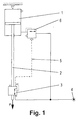
- the lifting device shown schematically in Fig. 1 consists of a pneumatic Cylinder 1, the elongated piston rod 2 is not one at its lower end shown load carries, from which the tensile force F results.
- the integrated pneumatic force transducer 3 which is fed by a compressed air source 4 and a control signal 5 proportional to the tensile force F via a control line 5 (Control pressure) to the pressure control valve 6, which also from the Compressed air source 4 is supplied and the compressed air with a control signal forwards corresponding pressure to cylinder 1.
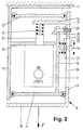
- the force transducer shown in a longitudinal section in FIG. 2 consists on the one hand of a sensor 7 and, on the other hand, a mechanical structure 8, which consists of two longitudinal links 9, 10 running parallel to the tensile force direction (F) are formed, which at their ends are each articulated with two transverse to the direction of force Wishbones 11, 12 are connected to form a joint parallelogram.
- Each of the two trailing arms 9, 10 has one fixed within the parallelogram connected to him cross members 13, 14, which are at an axial distance from each other are arranged.
- the sensor 7 is attached to the cross member 13.
- each trailing arm 9, 10 has one fixed to it connected cross support 16, 17, wherein on the lower cross support 16 tensile force F to be measured.
- An equally large counterforce engages the top of the Cross support 17 on.
- FIG. 2 shows within the parallelogram one parallel to the trailing arm 9 extending longitudinal beam 18, which has its lower end on the wishbone 11 is attached. Between the side member 18 and the trailing arm 9 are one Support 19 and a compression spring 20 as the first elastic element in series arranged.
- This configuration transforms the tensile force F into a first and a second partial force disassembled, the first partial force over the compression spring 15 on the sensor 7 and the second partial force via the compression spring 20 on the trailing arm 9 of the mechanical structure 8 is supported.
- the ratio of the two partial forces to one another can be determined by a Longitudinal displacement of the support 19 along the trailing arm 9 in a large Range can be set.
- the support 19 is formed by a screw 22 which in one Internal thread of a spring plate 23 engages, which in turn the compression spring 20th supported.
- the screw 22 is in a longitudinal slot 24 of the trailing arm 9 slidably guided.
- the support 19 in can be fixed in any desired position.
- the trailing arm 9 Screw 25 attached, which has two spaced stops, namely the Screw collar 26 on the one hand and one placed on the screw 25 Spacer 27 on the other hand, the screw through a recess of the Sides 18 engages, thereby the longitudinal member 18 between the stops picks up and so the deflection or transverse displacement of the longitudinal beam 18th limited.
- the force transducer is formed by means of compression springs 15, 20 designed as a plate spring small-scale executable.
- Fig. 3 shows schematically a further embodiment of the embodiment, wherein on the trailing arm 10, which carries the cross member 13, an additional transverse carrier 28 is provided. This carries an adjusting screw 29, the acts on a helical spring 30, which one of the measuring sensor 7 (sensor element 21) Preload issued.
Landscapes
- Physics & Mathematics (AREA)
- General Physics & Mathematics (AREA)
- Force Measurement Appropriate To Specific Purposes (AREA)
- Investigating Strength Of Materials By Application Of Mechanical Stress (AREA)
- Transducers For Ultrasonic Waves (AREA)
- Fats And Perfumes (AREA)
Description
- Fig. 1
- ein pneumatisches Hebegerät in einer schematischen Darstellung,
- Fig. 2
- einen pneumatischen Kraftaufnehmer in einem Längsschnitt,
- Fig. 3
- eine Ausgestaltung des Kraftaufnehmers gemäss Fig. 2 und
- Fig. 4
- ein Kraft-Steuerdruck-Diagramm.
- 1
- Zylinder
- 2
- Kolbenstange
- 3
- Kraftaufnehmer
- 4
- Druckluftquelle
- 5
- Steuerleitung
- 6
- Druckregelventil
- 7
- Messfühler
- 8
- Struktur
- 9
- Längslenker
- 10
- Längslenker
- 11
- Querlenker
- 12
- Querlenker
- 13
- Querträger
- 14
- Querträger
- 15
- Druckfeder
- 16
- Querabstützung
- 17
- Querabstützung
- 18
- Längsträger
- 19
- Abstützung
- 20
- Druckfeder
- 21
- Fühlerelement
- 22
- Schraube
- 23
- Federteller
- 24
- Längsschlitz
- 25
- Schraube
- 26
- Schraubenbund
- 27
- Abstandsscheibe
- 28
- Träger
- 29
- Stellschraube
- 30
- Schraubenfeder
Claims (7)
- Kraftaufnehmer zur Messung einer Zugkraft (F) in einer pneumatischen Einrichtung,
mit einem Gelenkparallelogramm, das aus einem ersten und zweiten Längslenker (9, 10) und aus einem ersten und zweiten Querlenker (11, 12) gebildet ist, die jeweils mit Abstand parallel zueinander verlaufen und gelenkig miteinander verbunden sind,
wobei sich die beiden Längslenker (9, 10) parallel zur Richtung der Zugkraft (F) erstrecken und wobei die Zugkraft (F) an dem zweiten Längslenker (9) angreift und diesen in Richtung der Zugkraft (F) bewegt,
mit einem zwischen den beiden Querlenkern (11, 12) angeordneten, mit dem ersten Längslenker (10) fest verbundenen Messfühler (7) zur Erzeugung eines zugkraftabhängigen pneumatischen Drucksignals, der ein aus dem Messfühlergehäuse herausragendes Fühlerelement (21) aufweist,
das von einem Beaufschlagungselement in Abhängigkeit von der Zugkraft (F) kraftbeaufschlagbar ist, wobei entweder der zweite Längslenker (9) oder einer der beiden Querlenker (11, 12) das Beaufschlagungselement bildet,
dadurch gekennzeichnet, dass mindestens ein erstes elastisches Element (Druckfeder 20) mit mindestens zwei der Lenker (Längs- (9, 10) und/oder Querlenker (11, 12)) derart verbunden ist, dass die zugkraftbedingte Bewegung des zweiten Längslenkers (9) gegen eine von dem ersten Element (Druckfeder 20) bewirkte elastische Kraft erfolgt, und
dass das mit mindestens einem zweiten elastischen Element (Druckfeder 15) in Reihe geschaltete Fühlerelement (21) am Beaufschlagungselement abgestützt ist. - Kraftaufnehmer nach Anspruch 1,
dadurch gekennzeichnet, dass das erste und zweite elastische Element eine Druckfeder (15, 20) ist - Kraftaufnehmer nach Anspruch 2,
dadurch gekennzeichnet,
dadurch gekennzeichnet, dass die Druckfeder (15, 20) eine Tellerfeder ist - Kraftaufnehmer nach einem der Ansprüche 1 - 3,
dadurch gekennzeichnet, dass jeder Längslenker (9, 10) außerhalb des Parallelogramms an einem seiner beiden Enden eine fest mit ihm verbundenen Querabstützung (16, 17) aufweist, an denen in Richtung der Längsachse des Messfühlers (7) die zu messende Zugkraft (F) bzw. die entsprechende Gegenkraft angreift. - Kraftaufnehmer nach einem der Ansprüche 1 - 4,
dadurch gekennzeichnet, dass innerhalb des Parallelogramms an einem Querlenker (11) ein quer zu diesem verlaufender und fest mit diesem verbundener Längsträger (18) angeordnet ist, wobei zwischen dem unmittelbar gegenüberliegenden Längslenker (9) und dem Längsträger (18) das erste elastische Element abgestützt ist. - Kraftaufnehmer nach Anspruch 5,
dadurch gekennzeichnet, dass die Abstützung (19) am Längslenker (9) längsverschiebbar und arretierbar ist. - Kraftaufnehmer nach einem der Ansprüche 5 oder 6,
dadurch gekennzeichnet, dass an dem dem Längsträger (18) unmittelbar gegenüberliegenden Längslenker (9) eine Schraube befestigt ist, die zwei Anschläge (26, 27) aufweist, welche zur Begrenzung der Seitwärtsbewegung des Längsträgers (18) dienen.
Applications Claiming Priority (2)
| Application Number | Priority Date | Filing Date | Title |
|---|---|---|---|
| DE29822269U DE29822269U1 (de) | 1998-12-16 | 1998-12-16 | Pneumatischer Kraftaufnehmer |
| DE29822269U | 1998-12-16 |
Publications (3)
| Publication Number | Publication Date |
|---|---|
| EP1014063A2 EP1014063A2 (de) | 2000-06-28 |
| EP1014063A3 EP1014063A3 (de) | 2000-07-19 |
| EP1014063B1 true EP1014063B1 (de) | 2002-03-27 |
Family
ID=8066620
Family Applications (1)
| Application Number | Title | Priority Date | Filing Date |
|---|---|---|---|
| EP99250411A Expired - Lifetime EP1014063B1 (de) | 1998-12-16 | 1999-11-22 | Kraftaufnehmer |
Country Status (7)
| Country | Link |
|---|---|
| US (1) | US6276216B1 (de) |
| EP (1) | EP1014063B1 (de) |
| JP (1) | JP2000205980A (de) |
| AT (1) | ATE215220T1 (de) |
| CA (1) | CA2292081A1 (de) |
| DE (2) | DE29822269U1 (de) |
| ES (1) | ES2171321T3 (de) |
Families Citing this family (2)
| Publication number | Priority date | Publication date | Assignee | Title |
|---|---|---|---|---|
| US7090200B2 (en) | 2001-11-27 | 2006-08-15 | Morse Christopher J | Actuator |
| CN115979486B (zh) * | 2023-01-06 | 2024-08-09 | 南通杰品起重设备有限公司 | 一种绞车生产用的牵引力试验检测装置 |
Family Cites Families (9)
| Publication number | Priority date | Publication date | Assignee | Title |
|---|---|---|---|---|
| CH620995A5 (de) * | 1978-01-26 | 1980-12-31 | Wirth Gallo & Co | |
| CH623928A5 (de) * | 1978-02-02 | 1981-06-30 | Wirth Gallo & Co | |
| US4305300A (en) * | 1980-04-28 | 1981-12-15 | Mts Systems Corporation | Railway car side frame test machine |
| US4338825A (en) * | 1980-10-15 | 1982-07-13 | Eaton Corporation | Strain gage load cell |
| CH673531A5 (de) | 1987-08-08 | 1990-03-15 | Wirth Gallo Messtechnik | |
| DE4119734A1 (de) * | 1991-06-14 | 1992-12-17 | Mettler Toledo Ag | Vorrichtung zur kraftuntersetzung in einer kraftmesseinrichtung, insbesondere einer waage |
| DE4132108A1 (de) | 1991-09-26 | 1993-04-01 | Siemens Ag | Kraftsensor |
| DE4305914C1 (de) | 1993-02-26 | 1995-01-05 | Leopold Weinlich | Brems- und/oder Treibdynamometer mit Erfassung der Querkraft |
| DE4415518A1 (de) * | 1994-05-04 | 1995-11-09 | Zasche Foerdertechnik Gmbh | Balanciereinrichtung für handgeführte Manipulatoren |
-
1998
- 1998-12-16 DE DE29822269U patent/DE29822269U1/de not_active Expired - Lifetime
-
1999
- 1999-11-22 EP EP99250411A patent/EP1014063B1/de not_active Expired - Lifetime
- 1999-11-22 ES ES99250411T patent/ES2171321T3/es not_active Expired - Lifetime
- 1999-11-22 DE DE59901054T patent/DE59901054D1/de not_active Expired - Fee Related
- 1999-11-22 AT AT99250411T patent/ATE215220T1/de not_active IP Right Cessation
- 1999-11-29 US US09/451,035 patent/US6276216B1/en not_active Expired - Fee Related
- 1999-12-13 CA CA002292081A patent/CA2292081A1/en not_active Abandoned
- 1999-12-15 JP JP11355841A patent/JP2000205980A/ja active Pending
Also Published As
| Publication number | Publication date |
|---|---|
| CA2292081A1 (en) | 2000-06-16 |
| EP1014063A3 (de) | 2000-07-19 |
| JP2000205980A (ja) | 2000-07-28 |
| ES2171321T3 (es) | 2002-09-01 |
| EP1014063A2 (de) | 2000-06-28 |
| DE59901054D1 (de) | 2002-05-02 |
| DE29822269U1 (de) | 1999-03-25 |
| US6276216B1 (en) | 2001-08-21 |
| ATE215220T1 (de) | 2002-04-15 |
Similar Documents
| Publication | Publication Date | Title |
|---|---|---|
| DE2321190B2 (de) | Parabelfeder | |
| WO2011044958A1 (de) | Hebelarmprüfmaschine | |
| EP2615433B1 (de) | Vorrichtung und Verfahren zur Justierung des Eckenlastfehlers einer Parallelführung | |
| EP0548487B1 (de) | Einrichtung zur Messung einer Verformung eines Bauteils | |
| EP0987532B1 (de) | Messvorrichtung zur Bestimmung des Gesamtanzugsmoments, des Kopfreibungsmoments und der Vorspannkraft einer angezogenen Schraubverbindung | |
| DE3218529A1 (de) | Einstellbares gestaenge | |
| EP0947409B1 (de) | Schienenfahrzeug mit einem vertikalen Stützaktuator | |
| DE2815228B2 (de) | ||
| DE2813782A1 (de) | Hebelfreier waagensensor | |
| EP1671090A1 (de) | Kraftmessvorrichtung | |
| DE69516965T2 (de) | Oberschalige Waage | |
| DE2449648A1 (de) | Zugkraftfuehlvorrichtung fuer zugmaschinen | |
| EP0046462A1 (de) | Massen- und Kraftmessgerät | |
| DE102020133109B4 (de) | Messwiderlager und Trommelbremse mit einem Messwiderlager | |
| EP1530035B1 (de) | Kraftmesszelle mit Befestigungsentkopplung durch vorstehende Flächen und kurze Einschnitte | |
| EP1014063A2 (de) | Kraftaufnehmer | |
| CH669667A5 (de) | ||
| CH669043A5 (de) | Praezisionswaage. | |
| DE3119806C2 (de) | ||
| EP0003222A2 (de) | Massen- und Kraftmesser | |
| DE3626126C2 (de) | Anordnung für die Befestigungg von Verlagerungsfühlern an einer Säule | |
| AT374004B (de) | Vorrichtung zur gefederten einleitung einer zu messenden kraft in einen auf biegung beanspruchbaren messkoerper | |
| DE102020133111A1 (de) | Messwiderlager und Trommelbremse | |
| DE2531746A1 (de) | Massen- und kraftmessgeraet | |
| EP1044356A1 (de) | Kraftmesszelle |
Legal Events
| Date | Code | Title | Description |
|---|---|---|---|
| PUAI | Public reference made under article 153(3) epc to a published international application that has entered the european phase |
Free format text: ORIGINAL CODE: 0009012 |
|
| PUAL | Search report despatched |
Free format text: ORIGINAL CODE: 0009013 |
|
| AK | Designated contracting states |
Kind code of ref document: A2 Designated state(s): AT BE CH CY DE DK ES FI FR GB GR IE IT LI LU MC NL PT SE |
|
| AX | Request for extension of the european patent |
Free format text: AL;LT;LV;MK;RO;SI |
|
| AK | Designated contracting states |
Kind code of ref document: A3 Designated state(s): AT BE CH CY DE DK ES FI FR GB GR IE IT LI LU MC NL PT SE |
|
| AX | Request for extension of the european patent |
Free format text: AL;LT;LV;MK;RO;SI |
|
| RIC1 | Information provided on ipc code assigned before grant |
Free format text: 7G 01L 1/02 A, 7G 01L 1/26 B, 7G 01L 1/08 B |
|
| 17P | Request for examination filed |
Effective date: 20001103 |
|
| GRAG | Despatch of communication of intention to grant |
Free format text: ORIGINAL CODE: EPIDOS AGRA |
|
| AKX | Designation fees paid |
Free format text: AT BE CH CY DE DK ES FI FR GB GR IE IT LI LU MC NL PT SE |
|
| 17Q | First examination report despatched |
Effective date: 20010403 |
|
| GRAG | Despatch of communication of intention to grant |
Free format text: ORIGINAL CODE: EPIDOS AGRA |
|
| GRAH | Despatch of communication of intention to grant a patent |
Free format text: ORIGINAL CODE: EPIDOS IGRA |
|
| GRAH | Despatch of communication of intention to grant a patent |
Free format text: ORIGINAL CODE: EPIDOS IGRA |
|
| REG | Reference to a national code |
Ref country code: GB Ref legal event code: IF02 |
|
| GRAA | (expected) grant |
Free format text: ORIGINAL CODE: 0009210 |
|
| AK | Designated contracting states |
Kind code of ref document: B1 Designated state(s): AT BE CH CY DE DK ES FI FR GB GR IE IT LI LU MC NL PT SE |
|
| PG25 | Lapsed in a contracting state [announced via postgrant information from national office to epo] |
Ref country code: NL Free format text: LAPSE BECAUSE OF FAILURE TO SUBMIT A TRANSLATION OF THE DESCRIPTION OR TO PAY THE FEE WITHIN THE PRESCRIBED TIME-LIMIT Effective date: 20020327 Ref country code: IE Free format text: LAPSE BECAUSE OF FAILURE TO SUBMIT A TRANSLATION OF THE DESCRIPTION OR TO PAY THE FEE WITHIN THE PRESCRIBED TIME-LIMIT Effective date: 20020327 Ref country code: GR Free format text: LAPSE BECAUSE OF FAILURE TO SUBMIT A TRANSLATION OF THE DESCRIPTION OR TO PAY THE FEE WITHIN THE PRESCRIBED TIME-LIMIT Effective date: 20020327 Ref country code: FI Free format text: LAPSE BECAUSE OF FAILURE TO SUBMIT A TRANSLATION OF THE DESCRIPTION OR TO PAY THE FEE WITHIN THE PRESCRIBED TIME-LIMIT Effective date: 20020327 |
|
| REF | Corresponds to: |
Ref document number: 215220 Country of ref document: AT Date of ref document: 20020415 Kind code of ref document: T |
|
| REG | Reference to a national code |
Ref country code: CH Ref legal event code: EP |
|
| REG | Reference to a national code |
Ref country code: CH Ref legal event code: NV Representative=s name: E. BLUM & CO. PATENTANWAELTE |
|
| GBT | Gb: translation of ep patent filed (gb section 77(6)(a)/1977) |
Effective date: 20020327 |
|
| REF | Corresponds to: |
Ref document number: 59901054 Country of ref document: DE Date of ref document: 20020502 |
|
| REG | Reference to a national code |
Ref country code: IE Ref legal event code: FG4D Free format text: GERMAN |
|
| PG25 | Lapsed in a contracting state [announced via postgrant information from national office to epo] |
Ref country code: PT Free format text: LAPSE BECAUSE OF FAILURE TO SUBMIT A TRANSLATION OF THE DESCRIPTION OR TO PAY THE FEE WITHIN THE PRESCRIBED TIME-LIMIT Effective date: 20020627 Ref country code: DK Free format text: LAPSE BECAUSE OF FAILURE TO SUBMIT A TRANSLATION OF THE DESCRIPTION OR TO PAY THE FEE WITHIN THE PRESCRIBED TIME-LIMIT Effective date: 20020627 |
|
| ET | Fr: translation filed | ||
| REG | Reference to a national code |
Ref country code: ES Ref legal event code: FG2A Ref document number: 2171321 Country of ref document: ES Kind code of ref document: T3 |
|
| NLV1 | Nl: lapsed or annulled due to failure to fulfill the requirements of art. 29p and 29m of the patents act | ||
| REG | Reference to a national code |
Ref country code: IE Ref legal event code: FD4D |
|
| PG25 | Lapsed in a contracting state [announced via postgrant information from national office to epo] |
Ref country code: LU Free format text: LAPSE BECAUSE OF NON-PAYMENT OF DUE FEES Effective date: 20021122 Ref country code: AT Free format text: LAPSE BECAUSE OF NON-PAYMENT OF DUE FEES Effective date: 20021122 |
|
| PG25 | Lapsed in a contracting state [announced via postgrant information from national office to epo] |
Ref country code: SE Free format text: LAPSE BECAUSE OF NON-PAYMENT OF DUE FEES Effective date: 20021123 Ref country code: ES Free format text: LAPSE BECAUSE OF NON-PAYMENT OF DUE FEES Effective date: 20021123 |
|
| PG25 | Lapsed in a contracting state [announced via postgrant information from national office to epo] |
Ref country code: CY Free format text: LAPSE BECAUSE OF FAILURE TO SUBMIT A TRANSLATION OF THE DESCRIPTION OR TO PAY THE FEE WITHIN THE PRESCRIBED TIME-LIMIT Effective date: 20021130 Ref country code: BE Free format text: LAPSE BECAUSE OF NON-PAYMENT OF DUE FEES Effective date: 20021130 |
|
| PLBE | No opposition filed within time limit |
Free format text: ORIGINAL CODE: 0009261 |
|
| STAA | Information on the status of an ep patent application or granted ep patent |
Free format text: STATUS: NO OPPOSITION FILED WITHIN TIME LIMIT |
|
| 26N | No opposition filed |
Effective date: 20021230 |
|
| BERE | Be: lapsed |
Owner name: *MANNESMANN A.G. Effective date: 20021130 |
|
| PG25 | Lapsed in a contracting state [announced via postgrant information from national office to epo] |
Ref country code: MC Free format text: LAPSE BECAUSE OF NON-PAYMENT OF DUE FEES Effective date: 20030601 |
|
| PG25 | Lapsed in a contracting state [announced via postgrant information from national office to epo] |
Ref country code: DE Free format text: LAPSE BECAUSE OF NON-PAYMENT OF DUE FEES Effective date: 20030603 |
|
| EUG | Se: european patent has lapsed | ||
| PG25 | Lapsed in a contracting state [announced via postgrant information from national office to epo] |
Ref country code: FR Free format text: LAPSE BECAUSE OF NON-PAYMENT OF DUE FEES Effective date: 20030731 |
|
| REG | Reference to a national code |
Ref country code: FR Ref legal event code: ST |
|
| PG25 | Lapsed in a contracting state [announced via postgrant information from national office to epo] |
Ref country code: GB Free format text: LAPSE BECAUSE OF NON-PAYMENT OF DUE FEES Effective date: 20031122 |
|
| PG25 | Lapsed in a contracting state [announced via postgrant information from national office to epo] |
Ref country code: LI Free format text: LAPSE BECAUSE OF NON-PAYMENT OF DUE FEES Effective date: 20031130 Ref country code: CH Free format text: LAPSE BECAUSE OF NON-PAYMENT OF DUE FEES Effective date: 20031130 |
|
| REG | Reference to a national code |
Ref country code: ES Ref legal event code: FD2A Effective date: 20031213 |
|
| GBPC | Gb: european patent ceased through non-payment of renewal fee |
Effective date: 20031122 |
|
| REG | Reference to a national code |
Ref country code: CH Ref legal event code: PL |
|
| PG25 | Lapsed in a contracting state [announced via postgrant information from national office to epo] |
Ref country code: IT Free format text: LAPSE BECAUSE OF NON-PAYMENT OF DUE FEES Effective date: 20051122 |