EP1014064B1 - Mesure de la poussée d'un rotor à l'aide de capteurs à fibres optiques - Google Patents
Mesure de la poussée d'un rotor à l'aide de capteurs à fibres optiques Download PDFInfo
- Publication number
- EP1014064B1 EP1014064B1 EP99310073A EP99310073A EP1014064B1 EP 1014064 B1 EP1014064 B1 EP 1014064B1 EP 99310073 A EP99310073 A EP 99310073A EP 99310073 A EP99310073 A EP 99310073A EP 1014064 B1 EP1014064 B1 EP 1014064B1
- Authority
- EP
- European Patent Office
- Prior art keywords
- initial gap
- bearing element
- rotor thrust
- reflecting surfaces
- housing
- Prior art date
- Legal status (The legal status is an assumption and is not a legal conclusion. Google has not performed a legal analysis and makes no representation as to the accuracy of the status listed.)
- Expired - Lifetime
Links
- 239000000835 fiber Substances 0.000 title claims description 9
- 238000005259 measurement Methods 0.000 title description 16
- 230000006835 compression Effects 0.000 claims description 7
- 238000007906 compression Methods 0.000 claims description 7
- 230000007423 decrease Effects 0.000 claims description 6
- 239000000853 adhesive Substances 0.000 claims description 5
- 230000001070 adhesive effect Effects 0.000 claims description 5
- 238000000034 method Methods 0.000 claims description 3
- 239000011521 glass Substances 0.000 claims description 2
- 239000012790 adhesive layer Substances 0.000 claims 2
- 239000011241 protective layer Substances 0.000 claims 1
- 230000003287 optical effect Effects 0.000 description 31
- 230000001939 inductive effect Effects 0.000 description 2
- 239000000463 material Substances 0.000 description 2
- 229920000914 Metallic fiber Polymers 0.000 description 1
- 230000008602 contraction Effects 0.000 description 1
- 230000001419 dependent effect Effects 0.000 description 1
- 238000010586 diagram Methods 0.000 description 1
- 230000008030 elimination Effects 0.000 description 1
- 238000003379 elimination reaction Methods 0.000 description 1
- 239000003365 glass fiber Substances 0.000 description 1
- 238000012986 modification Methods 0.000 description 1
- 230000004048 modification Effects 0.000 description 1
- 238000003530 single readout Methods 0.000 description 1
Images
Classifications
-
- G—PHYSICS
- G01—MEASURING; TESTING
- G01L—MEASURING FORCE, STRESS, TORQUE, WORK, MECHANICAL POWER, MECHANICAL EFFICIENCY, OR FLUID PRESSURE
- G01L5/00—Apparatus for, or methods of, measuring force, work, mechanical power, or torque, specially adapted for specific purposes
- G01L5/13—Apparatus for, or methods of, measuring force, work, mechanical power, or torque, specially adapted for specific purposes for measuring the tractive or propulsive power of vehicles
- G01L5/133—Apparatus for, or methods of, measuring force, work, mechanical power, or torque, specially adapted for specific purposes for measuring the tractive or propulsive power of vehicles for measuring thrust of propulsive devices, e.g. of propellers
-
- G—PHYSICS
- G01—MEASURING; TESTING
- G01L—MEASURING FORCE, STRESS, TORQUE, WORK, MECHANICAL POWER, MECHANICAL EFFICIENCY, OR FLUID PRESSURE
- G01L1/00—Measuring force or stress, in general
- G01L1/24—Measuring force or stress, in general by measuring variations of optical properties of material when it is stressed, e.g. by photoelastic stress analysis using infrared, visible light, ultraviolet
-
- G—PHYSICS
- G01—MEASURING; TESTING
- G01M—TESTING STATIC OR DYNAMIC BALANCE OF MACHINES OR STRUCTURES; TESTING OF STRUCTURES OR APPARATUS, NOT OTHERWISE PROVIDED FOR
- G01M13/00—Testing of machine parts
- G01M13/04—Bearings
Definitions
- the present invention relates to gas turbine engines and, more particularly, to measurement of rotor thrust on gas turbine engines.
- strain gage indicated output is dependent upon its temperature environment at any thrust load, thus inducing errors into the measurement.
- strain gages are subject to mechanical fatigue failure and, thus, loss of signal.
- a third problem is that the strain gages are subject to electrical magnetic interference or other induced electrical noise, thus inducing errors into the thrust load measurement.
- the strain gages are subject to hookup wiring configuration errors, resulting in a reversal of the indicated rotor thrust direction, meaning that the forward and aft thrust directions can be indicated incorrectly, unknowingly by the observer.
- a fifth problem encountered in the prior art is that the strain gages are not an absolute measurement, as they require an electrical tare balance and other thermal compensations.
- the required length of the strain gage extension leads contain a resistive load, producing a voltage drop from the strain gage sensor to the remote data readout system, and thereby producing an error in the thrust measurement.
- the temperature of the strain gage extension leads are subjected to various temperature gradients internally in the engine. This temperature change in the extension leads produces a change in the extension lead resistance, in turn producing an error in the thrust measurement.
- the electrical resistance strain gage possesses a calibration constant known as the gage factor. This constant is defined as the unit change of electrical resistance of the strain gage for a given strain input. This gage factor also varies as a function of temperature and can produce an error in the indicated thrust measurement.
- the present invention provides a rotor thrust measurement without the use of a traditional strain gage, thereby eliminating errors and problems consequent to the use of such a strain gage in rotor measurement applications.
- a system and method use an optical strain gage to measure engine bearing thrust.
- Reflecting surfaces, or mirrors, encapsulated in a housing are separated by an initial gap.
- An incoming fiber receives light from an interferometer and transmits the light to the reflecting surfaces, which then reflect the light back to the interferometer.
- An engine load is introduced into a bearing that transfers the engine load to the optical strain gage to cause the change in the initial optical gap.
- the bearing is either stretched or compressed, and transfers the load through the adhesive to the optical strain gage.
- An increase in the initial gap indicates tension and a decrease in the initial gap indicates compression.
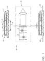
- Fig. 1 is a schematic block diagram of an optical strain gage rotor thrust measurement system, in accordance with the present invention.
- the fiber optic strain gage 10 comprises two reflecting surfaces, or mirrors, 12 and 14 which are encapsulated in a micro-tube 16, and an incoming fiber 17.
- a signal box such as a Fabry-Perot Interferometer (FPI) 26, and goes through mirror 14 to mirror 12, where it is reflected back through mirror 14, which is semi-transparent.
- FPI Fabry-Perot Interferometer
- the light is reflected back to the interferometer 26 from the mirrors 12 and 14, and the box 26 measures the interference.
- An increase in the gap between the mirrors, as interpreted by box 26, indicates tension; and a decrease in the gap between the mirrors 12, as interpreted by box 26, indicates compression.
- the space or optical gap 18 separating the mirrors 12 is defined as a cavity length L.
- the strain from the rotor thrust is induced into the bearing housing 20.
- a thin adhesive line or layer is introduced below the micro-tube and above the bearing, and then adhesive 22 covers the structure for protection.
- the strain is transferred into the optical strain gage as a cavity length 18 change.
- Arrows 23 represent the bearing housing load in a compression state; in a state of tension, the arrows would necessarily point outward, in the opposite direction.
- This change in cavity length as compared to the original gage length 24 can then be defined as the indicated strain level, and is measured at box 26.
- Light reflected in the FPI is wavelength modulated in response to the cavity length and any change in the cavity length.
- the optical strain gage 10 can detect changes in the cavity length in nanometers resolution.
- the optical strain gage is designed to be thermally self compensating. This feature can be achieved by constructing the strain gage so that reflecting surfaces 12 is made of a metallic fiber similar to the bearing housing parent material. Then, if the optical strain gage is submitted to a thermal cycle, the expansion or contraction will thermally match that of the parent bearing housing material.
- the optical strain gage does not have a metallic grid, as is found in an electrical resistance strain gage. Since the metallic grid in the electrical strain gages of the existing art are subject to fatigue type failures from alternating strain cycles, the elimination of this grid in the gage of the present invention provides an advantage. Instead, the primary component of the optical strain gage is the glass tube 16 in which the reflecting mirrors 12 and 14 are encapsulated.
- the optical strain gage being an optical device
- the optical strain gage is completely insensitive to EMI or any other type of electrical interference.
- the optical strain gage being an optical device and not an electrical resistive device, means that the strain gage of the present invention is not sensitive to lead length losses.
- the optical strain gage being an optical device with glass fibers transmitting light makes the gage insensitive to lead temperature in the engine environment.
- the optical strain gage being an optical device, does not have a "gage factor" calibration constant which varies as a function of temperature. The optical strain gage only measures the mechanical change of the cavity length which only varies as a function of the rotor thrust load input.
- the optical strain gage in accordance with the present invention, comprises a single readout and connector, so that it is not possible to connect the optical strain gage to the readout device and measure the thrust load in the undesired reverse direction.
- the optical strain gage is an absolute type measurement.
- the only variable that will affect the output of this optical strain gage is a mechanical deflection of the gage cavity induced by rotor thrust force into the bearing housing.
- the system can be disconnected at any time and reconnected with out any tare adjustments, calibrations or other compensations. With the optical strain gage of the present invention, the measurement of the direction of rotor thrust load is always absolute.
- the optical strain gage has the ability to measure the cavity length to a very high resolution, typically 0.001 micrometers, resulting in a high accuracy rotor thrust measurement.
- the optical strain gage of the present invention further has the ability to measure the actual deflection of the parent bearing housing with a resolution of nanometers, thus providing an additional piece of engineering information about the engine bearing.
- the present invention proposes a novel use of an optical strain gage, specifically, to measure the interference between two waves.
- the rotor thrust load is in tension; and when the cavity decreases, the rotor thrust load is in compression. This change in cavity length as compared to the original gage length is used to measure rotor thrust on a gas turbine engine.
Landscapes
- Physics & Mathematics (AREA)
- General Physics & Mathematics (AREA)
- Chemical & Material Sciences (AREA)
- Engineering & Computer Science (AREA)
- Combustion & Propulsion (AREA)
- Ocean & Marine Engineering (AREA)
- Force Measurement Appropriate To Specific Purposes (AREA)
- Length Measuring Devices By Optical Means (AREA)
Claims (10)
- Système (10) pour mesurer la poussée d'un rotor de moteur comprenant :une première et une seconde surface réfléchissante (12, 14) encapsulées dans un boítier (16), les première et seconde surfaces réfléchissantes (12, 14) étant séparées par un interstice initial (18),une fibre d'entrée (17) pour transmettre de la lumière aux première et seconde surfaces réfléchissantes (12, 14),un palier (20) collé au boítier (16),un moyen pour introduire une charge de moteur dans le palier (20), la poussée du rotor dans le palier provoquant un changement de l'interstice initial (18), etun moyen pour interpréter le changement de l'interstice initial (18), une augmentation de l'interstice initial (18) indiquant une traction et une diminution de l'interstice initial (18) indiquant une compression.
- Système selon la revendication 1, dans lequel le moyen pour interpréter le changement de l'interstice initial (18) comprend un interféromètre (26).
- Système selon la revendication 2, dans lequel la fibre d'entrée (17) comprend en outre une fibre d'entrée pour recevoir de la lumière provenant de l'interféromètre (26).
- Système selon la revendication 1, dans lequel le moyen pour introduire une charge de moteur dans le palier (20) comprend en outre un moyen pour introduire une poussée de rotor dans le palier.
- Système selon la revendication 1, dans lequel les première et seconde surfaces réfléchissantes comprennent des miroirs (12, 14).
- Système selon la revendication 1, comprenant en outre une couche adhésive mince entre le boítier (16) et le palier (20).
- Système selon la revendication 6, comprenant en outre une couche protectrice adhésive (22) autour du boítier (16), du palier (20) et de la couche adhésive mince.
- Système selon la revendication 1, dans lequel le système (10) comprend un système thermiquement autocompensateur.
- Système selon la revendication 1, dans lequel le boítier comprend un tube de verre (16).
- Procédé pour mesurer la poussée d'un rotor de moteur comprenant les étapes consistant à :prendre une première et une seconde surface réfléchissante (12, 14), les première et seconde surfaces réfléchissantes étant séparées par un interstice initial (18),encapsuler les première et seconde surfaces réfléchissantes (12, 14) dans un boítier (16),transmettre de la lumière aux première et seconde surfaces réfléchissantes (12, 14),coller un palier (20) au boítier (16),introduire une charge de moteur dans le palier (16), la poussée du rotor dans le palier (16) provoquant un changement de l'interstice initial (18), etinterpréter le changement de l'interstice initial (18), une augmentation de l'interstice initial indiquant une traction et une diminution de l'interstice initial indiquant une compression.
Applications Claiming Priority (2)
| Application Number | Priority Date | Filing Date | Title |
|---|---|---|---|
| US215864 | 1998-12-18 | ||
| US09/215,864 US6141087A (en) | 1998-12-18 | 1998-12-18 | System and method for measuring engine rotor thrust using Fabry-Perot fiber sensor |
Publications (3)
| Publication Number | Publication Date |
|---|---|
| EP1014064A2 EP1014064A2 (fr) | 2000-06-28 |
| EP1014064A3 EP1014064A3 (fr) | 2000-07-12 |
| EP1014064B1 true EP1014064B1 (fr) | 2002-05-22 |
Family
ID=22804721
Family Applications (1)
| Application Number | Title | Priority Date | Filing Date |
|---|---|---|---|
| EP99310073A Expired - Lifetime EP1014064B1 (fr) | 1998-12-18 | 1999-12-15 | Mesure de la poussée d'un rotor à l'aide de capteurs à fibres optiques |
Country Status (4)
| Country | Link |
|---|---|
| US (1) | US6141087A (fr) |
| EP (1) | EP1014064B1 (fr) |
| JP (1) | JP2000321030A (fr) |
| DE (1) | DE69901529T2 (fr) |
Families Citing this family (16)
| Publication number | Priority date | Publication date | Assignee | Title |
|---|---|---|---|---|
| US6439767B1 (en) * | 1999-09-17 | 2002-08-27 | General Electric Company | Engine thrust bearing condition monitoring system and method |
| DE10136629B4 (de) | 2001-07-26 | 2010-05-20 | Eads Deutschland Gmbh | Verfahren und Vorrichtung zur meßtechnischen Erfassung von Lagerspielen in einer hochdynamischen mechanischen Übertragungskette |
| WO2005033643A2 (fr) * | 2003-10-03 | 2005-04-14 | Sabeus, Inc. | Capteur de pression robuste de type fabry-perrot |
| DE102004043754B3 (de) * | 2004-09-10 | 2006-04-20 | Fag Kugelfischer Ag & Co. Ohg | Messvorrichtung zum Erfassen von Belastungen einer Lagerung |
| DE102006007406B3 (de) * | 2006-02-17 | 2007-06-28 | Eads Space Transportation Gmbh | Schubmessbrücke und Verfahren zur messtechnischen Erfassung des Schubes von Triebwerken |
| DE102006059439B4 (de) | 2006-12-15 | 2018-01-25 | Prüftechnik Dieter Busch AG | Verfahren und Vorrichtung zur dynamischen Messung der axialen Deformation einer rotierenden Hohlwelle |
| US8333551B2 (en) * | 2007-09-28 | 2012-12-18 | General Electric Company | Embedded fiber optic sensing device and method |
| FR2929701B1 (fr) * | 2008-04-07 | 2011-01-07 | Commissariat Energie Atomique | Capteur d'allongement a fibre optique. |
| US8314925B2 (en) * | 2009-10-30 | 2012-11-20 | General Electric Company | Fiber-optic based thrust load measurement system |
| DE102011116975B3 (de) * | 2011-10-26 | 2013-03-21 | Airbus Operations Gmbh | Verfahren und Vorrichtung zum Bestimmen der Schubkraft eines Triebwerks an einem Fahrzeug |
| EP2982957B1 (fr) * | 2014-08-07 | 2017-11-29 | Siemens Aktiengesellschaft | Dispositif pour une mesure de butée de rotor, turbine et procédé pour mesurer une poussée de rotor d'une turbine |
| CN107389236B (zh) * | 2017-07-31 | 2018-07-10 | 中国人民解放军国防科学技术大学 | 基于斯托克斯参数测量的电推进领域微推力瞬态测量系统 |
| US10830092B2 (en) | 2018-03-07 | 2020-11-10 | General Electric Company | Bearing rotor thrust control |
| FR3080175B1 (fr) | 2018-04-13 | 2020-03-20 | Commissariat A L'energie Atomique Et Aux Energies Alternatives | Capteur a fibre optique de mesure de deformation fonctionnant en environnement severe |
| CN111059995B (zh) * | 2019-12-28 | 2020-12-25 | 浙江大学 | 一种基于摩擦纳米发电机的自驱动位移传感器 |
| CN114440781B (zh) * | 2022-01-21 | 2023-07-11 | 中国工程物理研究院流体物理研究所 | 一种间隙传感器、间隙测量方法及测量装置 |
Family Cites Families (5)
| Publication number | Priority date | Publication date | Assignee | Title |
|---|---|---|---|---|
| FR2346703A1 (fr) * | 1976-03-29 | 1977-10-28 | Abg Semca | Dispositif de mesure de poussee axiale d'un arbre de machine tournant |
| CA2074289C (fr) * | 1992-07-21 | 1999-09-14 | Claude Belleville | Capteur optique du type fabry-perot pour mesurer un parametre physique |
| CA2105605A1 (fr) * | 1993-09-07 | 1995-03-08 | Zhuo Jun Lu | Systeme a reseau de capteurs a fibres optiques servant a la mesure des deformations et des temperatures |
| US5594819A (en) * | 1995-07-26 | 1997-01-14 | Electric Power Research Institute | Field-mountable fiber optic sensors for long term strain monitoring in hostile environments |
| JP3638736B2 (ja) * | 1996-11-06 | 2005-04-13 | 株式会社共和電業 | 光ファイバ式ひずみゲージ |
-
1998
- 1998-12-18 US US09/215,864 patent/US6141087A/en not_active Expired - Fee Related
-
1999
- 1999-11-30 JP JP11339115A patent/JP2000321030A/ja not_active Withdrawn
- 1999-12-15 DE DE69901529T patent/DE69901529T2/de not_active Expired - Fee Related
- 1999-12-15 EP EP99310073A patent/EP1014064B1/fr not_active Expired - Lifetime
Also Published As
| Publication number | Publication date |
|---|---|
| US6141087A (en) | 2000-10-31 |
| DE69901529T2 (de) | 2003-01-09 |
| EP1014064A2 (fr) | 2000-06-28 |
| EP1014064A3 (fr) | 2000-07-12 |
| JP2000321030A (ja) | 2000-11-24 |
| DE69901529D1 (de) | 2002-06-27 |
Similar Documents
| Publication | Publication Date | Title |
|---|---|---|
| US6141087A (en) | System and method for measuring engine rotor thrust using Fabry-Perot fiber sensor | |
| US5528367A (en) | In-line fiber etalon strain sensor | |
| US5877426A (en) | Bourdon tube pressure gauge with integral optical strain sensors for measuring tension or compressive strain | |
| US5844667A (en) | Fiber optic pressure sensor with passive temperature compensation | |
| CA2447388C (fr) | Capteur de couple et de contrainte de fibre optique insensible a la temperature | |
| US6671055B1 (en) | Interferometric sensors utilizing bulk sensing mediums extrinsic to the input/output optical fiber | |
| US6776049B2 (en) | System and method for measuring stress at an interface | |
| Liu et al. | A multiplexed optical fibre-based extrinsic Fabry-Perot sensor system for in-situ strain monitoring in composites | |
| US5258614A (en) | Optical fiber loop temperature sensor | |
| US5196694A (en) | Temperature compensated self-referenced fiber optic microbend pressure transducer | |
| Liu et al. | Fiber Bragg grating based displacement sensors: State of the art and trends | |
| CN112525372B (zh) | 基于保偏光纤双臂异轴干涉仪的应变温度同时测量装置及方法 | |
| US4524322A (en) | Fiber optic system for measuring electric fields | |
| US5187983A (en) | Fiber-optic strain gauge manometer | |
| Xu et al. | Miniature temperature-insensitive Fabry-Pe/spl acute/rot fiber-optic pressure sensor | |
| Tjin et al. | A pressure sensor using fiber Bragg grating | |
| JPS63117205A (ja) | マイクロベンドファイバオプチックひずみゲージ | |
| US5020379A (en) | Microbend fiber optic strain gauge | |
| US5270538A (en) | System for accurately detecting changes in temperature and pressure | |
| CN114235035A (zh) | 一种基于光纤光栅的扭矩及温度多参量传感装置 | |
| Yuan et al. | Fiber optic differential interferometer | |
| Ecke et al. | Low-cost optical temperature and strain sensing networks using in-line fiber gratings | |
| Abu-Mahfouz | Strain Gauge | |
| CN217520625U (zh) | 一种基于莫尔条纹原理的高分辨驱动轴扭矩传感系统 | |
| Wild | Optimising the design of a pressure transducer for aircraft altitude measurement using optical fibre Bragg grating sensors |
Legal Events
| Date | Code | Title | Description |
|---|---|---|---|
| PUAI | Public reference made under article 153(3) epc to a published international application that has entered the european phase |
Free format text: ORIGINAL CODE: 0009012 |
|
| PUAL | Search report despatched |
Free format text: ORIGINAL CODE: 0009013 |
|
| AK | Designated contracting states |
Kind code of ref document: A2 Designated state(s): DE FR GB |
|
| AX | Request for extension of the european patent |
Free format text: AL;LT;LV;MK;RO;SI |
|
| AK | Designated contracting states |
Kind code of ref document: A3 Designated state(s): AT BE CH CY DE DK ES FI FR GB GR IE IT LI LU MC NL PT SE |
|
| AX | Request for extension of the european patent |
Free format text: AL;LT;LV;MK;RO;SI |
|
| RIC1 | Information provided on ipc code assigned before grant |
Free format text: 7G 01L 5/13 A, 7G 01L 1/24 B, 7G 01M 13/04 B |
|
| 17P | Request for examination filed |
Effective date: 20010112 |
|
| AKX | Designation fees paid |
Free format text: DE FR GB |
|
| GRAG | Despatch of communication of intention to grant |
Free format text: ORIGINAL CODE: EPIDOS AGRA |
|
| GRAG | Despatch of communication of intention to grant |
Free format text: ORIGINAL CODE: EPIDOS AGRA |
|
| GRAH | Despatch of communication of intention to grant a patent |
Free format text: ORIGINAL CODE: EPIDOS IGRA |
|
| 17Q | First examination report despatched |
Effective date: 20011004 |
|
| GRAH | Despatch of communication of intention to grant a patent |
Free format text: ORIGINAL CODE: EPIDOS IGRA |
|
| GRAA | (expected) grant |
Free format text: ORIGINAL CODE: 0009210 |
|
| REG | Reference to a national code |
Ref country code: GB Ref legal event code: FG4D |
|
| REF | Corresponds to: |
Ref document number: 69901529 Country of ref document: DE Date of ref document: 20020627 |
|
| ET | Fr: translation filed | ||
| PGFP | Annual fee paid to national office [announced via postgrant information from national office to epo] |
Ref country code: FR Payment date: 20021119 Year of fee payment: 4 |
|
| PGFP | Annual fee paid to national office [announced via postgrant information from national office to epo] |
Ref country code: DE Payment date: 20021230 Year of fee payment: 4 |
|
| PLBE | No opposition filed within time limit |
Free format text: ORIGINAL CODE: 0009261 |
|
| STAA | Information on the status of an ep patent application or granted ep patent |
Free format text: STATUS: NO OPPOSITION FILED WITHIN TIME LIMIT |
|
| 26N | No opposition filed |
Effective date: 20030225 |
|
| PG25 | Lapsed in a contracting state [announced via postgrant information from national office to epo] |
Ref country code: GB Free format text: LAPSE BECAUSE OF NON-PAYMENT OF DUE FEES Effective date: 20031215 |
|
| PG25 | Lapsed in a contracting state [announced via postgrant information from national office to epo] |
Ref country code: DE Free format text: LAPSE BECAUSE OF NON-PAYMENT OF DUE FEES Effective date: 20040701 |
|
| GBPC | Gb: european patent ceased through non-payment of renewal fee |
Effective date: 20031215 |
|
| PG25 | Lapsed in a contracting state [announced via postgrant information from national office to epo] |
Ref country code: FR Free format text: LAPSE BECAUSE OF NON-PAYMENT OF DUE FEES Effective date: 20040831 |
|
| REG | Reference to a national code |
Ref country code: FR Ref legal event code: ST |