EP1014082B1 - Überwachung des Zustandes von einem Fluidum - Google Patents
Überwachung des Zustandes von einem Fluidum Download PDFInfo
- Publication number
- EP1014082B1 EP1014082B1 EP99124893A EP99124893A EP1014082B1 EP 1014082 B1 EP1014082 B1 EP 1014082B1 EP 99124893 A EP99124893 A EP 99124893A EP 99124893 A EP99124893 A EP 99124893A EP 1014082 B1 EP1014082 B1 EP 1014082B1
- Authority
- EP
- European Patent Office
- Prior art keywords
- fluid
- current
- voltage
- frequency
- measured
- Prior art date
- Legal status (The legal status is an assumption and is not a legal conclusion. Google has not performed a legal analysis and makes no representation as to the accuracy of the status listed.)
- Expired - Lifetime
Links
- 239000012530 fluid Substances 0.000 title claims abstract description 92
- 238000012544 monitoring process Methods 0.000 title claims abstract description 13
- 238000000034 method Methods 0.000 claims description 16
- 238000006243 chemical reaction Methods 0.000 claims description 4
- 230000010355 oscillation Effects 0.000 claims description 4
- 230000004075 alteration Effects 0.000 claims 1
- 239000000523 sample Substances 0.000 abstract description 33
- 230000005540 biological transmission Effects 0.000 abstract description 15
- 238000011109 contamination Methods 0.000 abstract description 13
- 239000010705 motor oil Substances 0.000 abstract description 6
- 238000005259 measurement Methods 0.000 description 16
- 230000006870 function Effects 0.000 description 10
- 238000010586 diagram Methods 0.000 description 8
- 239000000758 substrate Substances 0.000 description 8
- PXHVJJICTQNCMI-UHFFFAOYSA-N Nickel Chemical compound [Ni] PXHVJJICTQNCMI-UHFFFAOYSA-N 0.000 description 6
- 239000002826 coolant Substances 0.000 description 6
- 230000006866 deterioration Effects 0.000 description 6
- 230000005284 excitation Effects 0.000 description 6
- 230000001050 lubricating effect Effects 0.000 description 6
- 238000004422 calculation algorithm Methods 0.000 description 5
- 239000011521 glass Substances 0.000 description 5
- 238000012360 testing method Methods 0.000 description 5
- 239000003990 capacitor Substances 0.000 description 4
- 239000011248 coating agent Substances 0.000 description 4
- 238000000576 coating method Methods 0.000 description 4
- 238000001566 impedance spectroscopy Methods 0.000 description 4
- 239000000314 lubricant Substances 0.000 description 4
- 239000010687 lubricating oil Substances 0.000 description 4
- 229920001343 polytetrafluoroethylene Polymers 0.000 description 4
- 239000004810 polytetrafluoroethylene Substances 0.000 description 4
- LFQSCWFLJHTTHZ-UHFFFAOYSA-N Ethanol Chemical compound CCO LFQSCWFLJHTTHZ-UHFFFAOYSA-N 0.000 description 3
- 238000002485 combustion reaction Methods 0.000 description 3
- 229910052759 nickel Inorganic materials 0.000 description 3
- 239000003921 oil Substances 0.000 description 3
- LYCAIKOWRPUZTN-UHFFFAOYSA-N Ethylene glycol Chemical compound OCCO LYCAIKOWRPUZTN-UHFFFAOYSA-N 0.000 description 2
- 235000014676 Phragmites communis Nutrition 0.000 description 2
- 230000032683 aging Effects 0.000 description 2
- 239000000919 ceramic Substances 0.000 description 2
- 239000000356 contaminant Substances 0.000 description 2
- 239000003989 dielectric material Substances 0.000 description 2
- 230000000694 effects Effects 0.000 description 2
- 238000002847 impedance measurement Methods 0.000 description 2
- 239000000463 material Substances 0.000 description 2
- BASFCYQUMIYNBI-UHFFFAOYSA-N platinum Chemical compound [Pt] BASFCYQUMIYNBI-UHFFFAOYSA-N 0.000 description 2
- 230000001681 protective effect Effects 0.000 description 2
- 239000000126 substance Substances 0.000 description 2
- XLYOFNOQVPJJNP-UHFFFAOYSA-N water Substances O XLYOFNOQVPJJNP-UHFFFAOYSA-N 0.000 description 2
- RYGMFSIKBFXOCR-UHFFFAOYSA-N Copper Chemical compound [Cu] RYGMFSIKBFXOCR-UHFFFAOYSA-N 0.000 description 1
- 239000004697 Polyetherimide Substances 0.000 description 1
- RTAQQCXQSZGOHL-UHFFFAOYSA-N Titanium Chemical compound [Ti] RTAQQCXQSZGOHL-UHFFFAOYSA-N 0.000 description 1
- 238000000627 alternating current impedance spectroscopy Methods 0.000 description 1
- 230000002925 chemical effect Effects 0.000 description 1
- 238000010276 construction Methods 0.000 description 1
- 229910052802 copper Inorganic materials 0.000 description 1
- 239000010949 copper Substances 0.000 description 1
- 238000001514 detection method Methods 0.000 description 1
- 238000011156 evaluation Methods 0.000 description 1
- 230000014509 gene expression Effects 0.000 description 1
- WGCNASOHLSPBMP-UHFFFAOYSA-N hydroxyacetaldehyde Natural products OCC=O WGCNASOHLSPBMP-UHFFFAOYSA-N 0.000 description 1
- 239000007788 liquid Substances 0.000 description 1
- 229910052751 metal Inorganic materials 0.000 description 1
- 239000002184 metal Substances 0.000 description 1
- 238000003801 milling Methods 0.000 description 1
- 238000012986 modification Methods 0.000 description 1
- 230000004048 modification Effects 0.000 description 1
- 238000000206 photolithography Methods 0.000 description 1
- 239000004033 plastic Substances 0.000 description 1
- 229920003023 plastic Polymers 0.000 description 1
- 229910052697 platinum Inorganic materials 0.000 description 1
- 229920001601 polyetherimide Polymers 0.000 description 1
- -1 polytetrafluoroethylene Polymers 0.000 description 1
- 230000004044 response Effects 0.000 description 1
- 239000010936 titanium Substances 0.000 description 1
- 229910052719 titanium Inorganic materials 0.000 description 1
Images




Classifications
-
- G—PHYSICS
- G01—MEASURING; TESTING
- G01N—INVESTIGATING OR ANALYSING MATERIALS BY DETERMINING THEIR CHEMICAL OR PHYSICAL PROPERTIES
- G01N27/00—Investigating or analysing materials by the use of electric, electrochemical, or magnetic means
- G01N27/02—Investigating or analysing materials by the use of electric, electrochemical, or magnetic means by investigating impedance
- G01N27/04—Investigating or analysing materials by the use of electric, electrochemical, or magnetic means by investigating impedance by investigating resistance
-
- G—PHYSICS
- G01—MEASURING; TESTING
- G01N—INVESTIGATING OR ANALYSING MATERIALS BY DETERMINING THEIR CHEMICAL OR PHYSICAL PROPERTIES
- G01N27/00—Investigating or analysing materials by the use of electric, electrochemical, or magnetic means
- G01N27/02—Investigating or analysing materials by the use of electric, electrochemical, or magnetic means by investigating impedance
- G01N27/22—Investigating or analysing materials by the use of electric, electrochemical, or magnetic means by investigating impedance by investigating capacitance
- G01N27/221—Investigating or analysing materials by the use of electric, electrochemical, or magnetic means by investigating impedance by investigating capacitance by investigating the dielectric properties
-
- G—PHYSICS
- G01—MEASURING; TESTING
- G01N—INVESTIGATING OR ANALYSING MATERIALS BY DETERMINING THEIR CHEMICAL OR PHYSICAL PROPERTIES
- G01N33/00—Investigating or analysing materials by specific methods not covered by groups G01N1/00 - G01N31/00
- G01N33/26—Oils; Viscous liquids; Paints; Inks
- G01N33/28—Oils, i.e. hydrocarbon liquids
- G01N33/2888—Lubricating oil characteristics, e.g. deterioration
Definitions
- Patent 5,274,335 issued to Wang, et al.
- U.S. Patent 4,646,070 issued to Yasuhara, et al.
- These systems describe the application of electro-impedance spectroscopy techniques for determining the condition of internal combustion engine lubricating oil due to contamination with engine coolant and to deterioration due to the chemical effect of the products of combustion and aging on the engine lubricating oil.
- the aforesaid known systems employ the technique of applying an AC signal current relatively high frequency to the plates of a capacitor and determining the change in the impedance measured thereon. Typically such frequencies are in the multi-hertzian range of generally between 10 hertz and 500 kilohertz.
- JP-57108650 discloses a device for detecting mixing ratio of alcohol and water content ratio by measuring the impedance between a pair of electrodes immersed in liquid including alcohol by two different frequencies and computing two measured impedance values.
- the impedance value obtained at one of the frequencies is considered to correspond to the alcohol mixing ratio while the water content ratio is calculated by using a particular algorithm.
- DE-1498815 refers to a measuring assembly for detecting a characteristic of a dielectric material comprising a pair of electrodes that are disposed in a spaced apart arrangement and that are immersed at least partially in a fluid to be tested.
- the present invention as defined in claim 1 employs a low level oscillating voltage signal across the plates or spaced electrodes of a capacitor immersed in the fluid to be monitored and measures the current of the signal applied at a first or high frequency associated with the bulk impedance of the fluid and at a second low frequency associated with the electrochemical properties of the surface of the electrode and determines the difference of the first and second measured currents.
- the current measured for the higher frequency is compared with measurements at the same frequency for acceptable fluid to determine if the current reading for the higher frequency associated with bulk impedance measurements is within predetermined limits.
- current is measured and converted to a voltage for purposes of the comparison.
- the present invention thus provides a simple, low cost technique for real time on-board monitoring of lubricating fluid employed in engines and power transmissions of motor vehicles and other working fluid system applications.
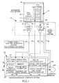
- the basic system of the invention is indicated generally at 10 as having a probe assembly indicated generally at 12 which is immersed at least partially in fluid 14 contained in a receptacle 16 which may be an engine crankcase or power transmission housing or other fluid vessel.
- the probe assembly will be described in greater detail hereinafter; and, a temperature sensor comprising a resistive temperature device 18 is also immersed in the fluid 14.
- the probe 12 receives an input along line 24 from the AC excitation section 20 of the microprocessor base microcontroller, indicated generally at 22, and, the output of the probe assembly 12 is provided along line 26, which has a grounded shield 28, to the input of an amplifier and current to voltage converter 30 which has its output connected along line 32 to the signal acquisition section 34 of microcontroller 22.
- the temperature sensor 18 is connected through lines 36, 38 with the lines having a grounded shield 42 to the input of an amplifier 40.
- the output of the amplifier 40 is also connected along line 43 to the signal acquisition section 34.
- the amplifier/current to voltage converter 30 has an "auto range" gain control function and is connected to receive inputs along lines 44, 46 from digital controller section 48 of microcontroller 22.
- the microcontroller has a digital output line section 50 which is connected along line 52 to a condition warning indicator 54 to provide excitation thereof.
- the microcontroller 22 includes an eight bit microprocessor 56, a memory section 58, embedded software containing the algorithm for probe 12, as denoted by section 60, and an address and data control function section 62 with the timing trigger and interrupt control being performed by section 64.
- probe 12 and temp sensor 18 may be mounted on a common support structure for connection through an opening in the housing or casing 16.
- the temp sensor 18 is conventionally connected in a Wheatstone bridge circuit and forms one leg thereof; and, therefore the details of the circuit therefor have been omitted for the sake of brevity.
- the sensor 18 is a platinum element on a ceramic substrate and has a resistance change proportional to temperature with a nominal resistance of 100 ohms at 0° Centigrade and a positive temperature coefficient of 0.00385 ohms per ohm per degree Centigrade.
- a suitable ceramic substrate employed in the present practice of the invention measured about 2 by 2 by 1.3 millimeters.
- the sensor 18 was surrounded by a protective copper tube (not shown in FIG. 1).
- the amplifiers 30, 40 are mounted as close to the housing or casing 16 as is practical and may be enclosed in a suitable protective enclosure denoted by reference numeral 17 and illustrated in dashed outline in FIG. 1.
- a suitable protective enclosure denoted by reference numeral 17 and illustrated in dashed outline in FIG. 1.
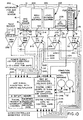
- amplifier 30 receives a current signal from probe output line 26 at its input connection which signal is applied to the inverting input of device IC-1 which is protected by a guard ring shown in dashed outline denoted by reference numeral 66.
- the probe 12 is excited by a constant supply voltage having a 1.0 volts A.C. RMS, 1.6 volts peak magnitude at a first and second oscillation frequency preferably comprising a sinusoidal alternating zero crossing wave form. It will be understood however that other forms of oscillating voltage may be employed.
- Diodes D1 and D2 prevent the input from being driven above or below the power supply voltage and are connected to the input line at junction 68 and respectively to pins 7 and 4 of IC-1.
- the device IC-1 is a Burr-Brown Part No. OPA128 or may comprise an analog device part No. 549 current to voltage conversion device.
- the positive input of IC-1 is grounded through junction 70.
- the output of IC-1 is connected to line 32 through junction 72 which also is connected through a resistor network to junction 74 which is connected to the input line of IC-1.
- the resistor network includes R1 connected on a leg between junction 72 and junction 74 and a leg connected in parallel therewith comprising switch SW1 and series resistors R2 and R3.
- Another leg is also connected in parallel with R1 and comprises switch SW2 in series with resistor R4.
- the resistor network is required to automatically adjust the gain due to the three decade swing of the input current signal from the probe 12.
- the computer sequentially activates the switches SW1, SW2 to close to maintain output voltage at plus or minus 8.5 volts peak 6 volts A.C. RMS.
- Resistor R5 connected between pins 5 and 1 of IC-1 is a variable potentiometer provided for zero adjustment.
- the switches SW1, SW2 are magnetically actuated glass reed switches and are closed by energization of the relay coils denoted respectively 76, 78 which are connected each along one of the lines 44, 46 on one side thereof; and, the opposite side of each coil 76, 78 is connected to receive 10 to 15 volts DC from the power supply.
- the resistor network serves to adjust the gain of the device IC-1 by changing the level of resistance in the feedback loop comprising the resistor network.
- the default gain with SW1 and SW2 both open is only R1 acting as the feedback resistor and provides a conversion of one volt per nano-amp input to IC-1.
- the effective resistance of resistors R1, R2 and R3 provides a conversion of 0.1 volts per nano-amp; and, with SW1 and SW2 both closed and R4 connected to the network, the effective gain is 1.01 volt per nano-amp.
- SW1 and SW2 being glass reed relays provide extremely high leakage resistance and low capacitance.
- the gain of the amplifier 30 is adjusted individually as needed until a complete acquisition sequence can be accomplished.
- the acquisition section 34 accomplishes this by "auto ranging” by responding to saturation by sending a logic signal to the control amp gain section 48 which in turn supplies current signals to the respective relay coils in the amplifier section 30 for controlling switches SW1, SW2. It has been determined that the probe 12 needs to function at temperatures up to 90° Centigrade and thus a range of multiple decades of amplifier gain control may be required.
- step 84 the system control functions are illustrated in the form of a block diagram in which the maximum output of amplifier 30 is determined for a given signal cycle at step 80 and the status of switches SW1, SW2 is determined at step 82.
- the status from step 82 is utilized at step 84 to determine whether SW1 is open and switch SW2 is closed. If the determination is affirmative, the system proceeds to step 86 to open switch SW2 and change the gain of IC-1 to the next higher level. If however, the determination at step 84 is negative, the system proceeds to step 88 to determine if the amplitude A max is greater than 0.85 volts and equal to or less than 8.50 volts. If the determination at step 88 is positive, the system proceeds to step 90 to maintain the existing status of switches SW1, SW2.
- step 88 determines whether the determination at step 88 is negative. If the determination at step 88 is negative, the system proceeds to step 92 to determine if A max is equal to or less than 0.85 volts; and, if affirmative, the system proceeds to step 94 and asks if SW1 and SW2 are both open. If the determination at step 92 is negative and a A max is greater than 8.50 volts, the system proceeds to step 96 and asks if SW1 and SW2 are both open.
- step 94 determines whether SW1 is closed and SW2 is open. If the determination at step 94 is positive, the system proceeds to step 95 and maintains the status of SW1 and SW2.
- step 98 If the determination at step 98 is positive, the system opens switch SW1 at step 99. If the determination at step 98 is negative implying that SW1 and SW2 are both closed, the system proceeds to open switch SW2 at step 100.
- step 96 determines at step 96 that SW1 and SW2 are open, the system proceeds to step 102 and closes switch SW1.
- step 96 determines whether SW1 is closed and SW2 is open. If the response to step 104 is affirmative, the system proceeds to step 106 to close switch SW2. If the determination at step 104 is negative implying SW1 and SW2 are both closed, the system proceeds to step 108 to keep the status of SW1 and SW2
- the mechanical construction of the probe 12 is shown as mounted on a base 110 which is mounted to a tubular hollow receptacle 112 which is threadedly engaged in an aperture provided through the wall of the casing or wall of fluid vessel 16 and secured therein by a lock nut 114.
- the receptacle 112 has a right angle configuration for receiving therein a cable 116 which contains the leads for electrical connection to the probe 12 and the temperature sensor 18.
- base 110 may have additional devices attached thereto as will be described hereinafter with respect to the embodiment of FIGS. 10 and 11.
- the probe 12 is supported by a supporting plate 118 which extends from the base 110 upwardly into the surrounding fluid within the casing 16. Electrical terminals such as terminal 120 extend from the support structure 118 through the base 110 to provide for electrical connection the leads 24, 26.
- the probe 12 is shown in the preferred practice as mounted on a substrate 122 which comprises a glass filled polytetrafluoroethylene (PTFE) substrate; and, the substrate 122 is mounted on the support structure 118 which preferably is formed of a high dielectric material such as polyetherimide plastic.
- a substrate 122 which comprises a glass filled polytetrafluoroethylene (PTFE) substrate; and, the substrate 122 is mounted on the support structure 118 which preferably is formed of a high dielectric material such as polyetherimide plastic.
- PTFE polytetrafluoroethylene
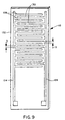
- the probe 12 includes two spaced electrodes 124, 126 formed on the substrate 122 with interdigitated fingers extending therefrom as illustrated in FIG. 9 to form an array of interdigitated parallel capacitive elements for each electrode denoted respectively by reference numerals 128, 130.
- the array of electrodes 124, 126 has a length of about two inches and a width of about one inch with the thickness denoted by dimension t in FIG. 9 of about 0.040 inches (1.0 millimeters).
- the spacing, denoted by reference character S in FIG. 9, is chosen in the range of about 0.127 millimeters to about 1.0 millimeters.
- the substrate 122 of the probe 12 is formed of a material having a low dielectric constant (high dielectric properties), a high bulk resistance and a high surface resistance preferably not less than 10 12 Ohm-cm.
- the circuitry employed for the embodiment 10 of FIG. 1 employing the probe 12 and circuitry of FIGS. 3 and 4 provides a system which measures the current in the probe which varies proportionally to the changes in impedance; and, therefore the measurement of current is considered to be a valid analog of the change in resistance.
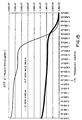
- a threshold value for the change in current ⁇ I I B - I S , where I S is the current measurement at the higher frequencies or frequencies above one hertz, has been established at a level of 4 nano amps. In other words, if a difference in current of at least four nano amps is detected by the system, the fluid is considered to be acceptable or in a non-contaminated condition and is suitable for continued usage.
- the system detects a ⁇ I or difference in current measured at frequently high frequencies and low frequencies of less than four nano amps, the system makes the determination that a significant level of contamination exists in the fluid and further usage should be prohibited and the system gives an indication that a fault condition exists.
- the system reads the temperature provided by temperature sensor 18 at step 132 and makes a determination at step 134 whether the temperature is below 60° Centigrade and if the result of the determination is positive, the system proceeds to step 136 and provides a fault indication and proceeds to step 138 to provide a warning disable signal which shuts down the condition warning light at 140.
- step 134 the system proceeds to step 142 and tests the fluid by applying a voltage F1 at a first frequency of about one hertz to about 100 hertz to determine the bulk impedance of the fluid; and, a second signal F2 is applied at a frequency of 30 millihertz to determine the surface characteristics of the electrode of the probe.
- the system proceeds to step 144 to calculate the difference D of signals F1 and F2.
- the system proceeds to step 146 to make a determination whether the difference D is greater than the threshold of four nano amps. If the determination of step 146 is positive the system provides an input signal to one input of AND gate 148. If the determination at step 146 is negative the system proceeds to an input an OR device 150 and illuminates a condition warning light at step 152.
- step 156 determines whether the warning light at 152 is a signal. If the determination at step 156 is negative, the system proceeds to provide a signal through OR gate 150 to activate the warning light at 152.
- FIG. 10 another embodiment of the system is indicated generally at 200 which employs the probe 12 of the embodiment 10 of FIG. 1 and also the temperature sensor 18 of the embodiment of FIG. 1 disposed in the fluid 14 of receptacle 16 the embodiment of FIG. 10 includes a level sensor indicated generally at 202 which may be mounted commonly on the base structure 110 as shown in FIGS. 6 through 8.
- the level sensor 202 includes a high level electrode plate 204 and an excitation electrode plate 206 which are of the same size and configuration and disposed in spaced parallel arrangement as illustrated in FIG. 6.
- a low level electrode plate 208 is disposed preferably on the support structure 118 for the fluid condition probe 12 and is intended for providing electrical indication of an unacceptable low level of the fluid 14 in receptacle 16.
- the electrodes 204, 206, 208 are excited with the same one hertz voltage as employed for the bulk impedance excitation of the fluid condition monitor probe 12.
- the electrode 204 provides an input to amplifier 210 along line 212 which is protected by grounded shield 214; and, the output of amplifier 210 is applied to the microcontroller indicated generally at 218 along line 26 to the signal acquisition section 220.
- Amplifier 210 receives gain control signals to provide auto ranging similar to amplifier 30 which signals are provided along lines 222, 224 from the digital control section 226 of the microcontroller 218.
- the excitation electrode 206 receives a signal along line 228 from the AC excitation section 230 of the microcontroller 218.
- the low level electrode 208 provides an output signal along line 232 to grounded shield 234 to amplifier 236.
- the output of amplifier 236 is applied along line 240 to the input of signal acquisition section 220 of microcontroller 218; and, amplifier 236 receives gain control signals along lines 242, 244 from the amp gain control section 226 of the microcontroller 218.
- the gain control function for amplifier 236 may be similar to that described for amplifier 30 with reference to FIG. 3 to prove an "auto control" function.
- the microcontroller 218 provides outputs from the digital section 246 to level warning light 248 along line 250 and to the condition warning light 54 along line 52.
- an optional tachometer sensor 252 may be employed which provides a signal along line 254 to a tachometer amplifier 256 whose output is applied to the signal acquisition section 220 along line 258.
- step 260 the operation of the system 200 of FIG. 10 is described in block flow diagram form where the system reads the RPM from the tachometer sensor 252 at step 260 and proceeds to step 262.
- the system also reads the temperature from sensor 18 at step 264 and proceeds to step 266 where a determination is made whether the temperature is less than 0° Centigrade in which case the system proceeds to step 268 to provide a fault signal and proceeds to step 270 to disable the level warning light 248.
- step 272 determines whether the temperature of the fluid is at 0° Centigrade or higher the system proceeds to step 272 to test the level by reading the outputs from electrodes 204, 202 and the system calculates the fluid level at step 274. The system then proceeds to step 262 and tests to determine whether the RPM is equal to or greater than a threshold level set at 300 RPM and if the fluid level is less than a predetermined threshold set at 20. If the determination is affirmative, the system proceeds to activate the level warning light 248. If however, the determination is negative the system proceeds to turn off the level warning light 248.
- the temperature read by the system at step 264 is also input to step 134 as described with reference to FIG. 2 and the remaining function of the system 200 is identical to that of FIG. 2 as indicated by common reference numerals for corresponding steps.
- the present invention thus provides a low cost and effective system for real time monitoring of the condition of a fluid in a fluid system, for example, lubricants in an engine or power transmission and provides continuing electrical indication of whether the fluid is suitable for a continued operation and optionally whether the fluid level is below an allowable minimum.
- the system employs electro-impedance spectroscopy whereby the fluid condition sensing probe has an array of parallel electrodes which are supplied with a constant level voltage at a first high frequency signal for determining the bulk impedance of the fluid and a second low frequency signal for determining the conditions on the electrode surface.
- the system electrically determines the difference in the current developed by the applied voltages and compares the current at the higher frequency with predetermined known conditions for the fluid and the current difference with a predetermined threshold to determine whether the fluid condition is acceptable for continued operation.
Landscapes
- Chemical & Material Sciences (AREA)
- Health & Medical Sciences (AREA)
- Life Sciences & Earth Sciences (AREA)
- Immunology (AREA)
- Pathology (AREA)
- Physics & Mathematics (AREA)
- Analytical Chemistry (AREA)
- Biochemistry (AREA)
- General Health & Medical Sciences (AREA)
- General Physics & Mathematics (AREA)
- Chemical Kinetics & Catalysis (AREA)
- Engineering & Computer Science (AREA)
- Electrochemistry (AREA)
- General Chemical & Material Sciences (AREA)
- Oil, Petroleum & Natural Gas (AREA)
- Food Science & Technology (AREA)
- Medicinal Chemistry (AREA)
- Investigating Or Analyzing Materials By The Use Of Electric Means (AREA)
- Lubrication Details And Ventilation Of Internal Combustion Engines (AREA)
- Fire-Detection Mechanisms (AREA)
- Investigating Or Analysing Materials By Optical Means (AREA)
Claims (10)
- Verfahren zur Erfassung oder Überwachung des Zustands eines Fluids in einem Fluidsystem, zu dem die Schritte gehören:(a) Bildung eines Elektrodenpaars und Anordnung der Elektroden in einer voneinander beabstandeten, zueinander im Wesentlichen parallelen Anordnung;(b) Eintauchen der Elektroden wenigstens teilweise in das Fluid;(c) Anlegen einer oszillierenden Spannung oder eines oszillierenden Stroms mit konstantem Scheitelwert und einer Frequenz an den Elektroden;(d) Anwendung der Spannung oder des Stroms bei einer verhältnismäßig hohen ersten Schwingungsfrequenz für eine Zeitdauer zur Messung des Körperwiderstands des Fluids;(e) Messung des Stroms oder der Spannung bei der ersten Frequenz und Vergleich des gemessenen Stroms oder der gemessenen Spannung mit bei der ersten Frequenz gemessenen Strömen oder Spannungen eines akzeptablen Fluids sowie Bestimmung, ob der bei der ersten Frequenz gemessene Strom oder die bei der ersten Frequenz gemessene Spannung innerhalb akzeptabler Grenzen liegt;(f) Anwendung der Spannung oder des Stroms bei einer verhältnismäßig niedrigen zweiten Schwingungsfrequenz, die dazu angepasst ist, um die Oberflächenimpedanz der Elektrode zu messen;(g) Messung des Stroms oder der Spannung bei der zweiten Schwingungsfrequenz und Berechnung der Differenz zwischen den Strömen oder Spannungen, die bei der ersten und der zweiten Frequenz gemessen werden;(h) Vergleich der berechneten Differenz der Ströme oder Spannungen mit einem Referenzwert, der einen vorbestimmten Fluidzustand kennzeichnet, und Bereitstellung einer elektrischen Anzeige für den Vergleich sowie Bestimmung, ob der Vergleich eine wesentliche Veränderung des Zustands des Fluids anzeigt.
- Verfahren nach Anspruch 1, wobei der Schritt des Anlegens einer oszillierenden Spannung oder eines oszillierenden Stroms das Anlegen einer oszillierenden Sinusspannung oder eines oszillierenden Sinusstroms mit konstantem Scheitelwert und den Schwingungsfrequenzen für die Zeitdauern an den Elektroden enthält.
- Verfahren nach Anspruch 1, wobei die Spannung oder der Strom, die den Elektroden zugeführt wird, in einer vorbestimmten Weise entsprechend der gemessenen Temperatur des Fluids verändert wird, um vorbestimmte Änderungen der Eigenschaften und des Zustands des Fluids, die durch Änderungen der Temperatur hervorgerufen sind, zu kompensieren.
- Verfahren nach Anspruch 1, wobei die Schritte der Messung der Ströme eine Wandlung der gemessenen Ströme in Spannungen enthalten und der Schritt der Berechnung eine Berechnung der Differenz zwischen den durch Umwandlung erhaltenen Spannungen enthält.
- Verfahren nach Anspruch 1, wobei der Schritt der Anordnung eine Anordnung der Elektroden in einem Abstand von ungefähr 0,12 bis ungefähr 1 mm zueinander enthält.
- Verfahren nach Anspruch 1, wobei der Schritt des Anlegens einer oszillierenden Spannung oder eines oszillierenden Stroms eine Anwendung der Spannung oder des Stroms im Wesentlichen bei einer Frequenz in dem Bereich von ungefähr 10 Hertz bis ungefähr 10 Kilohertz und bei einer Frequenz in dem Bereich zwischen ungefähr 1 Millihertz bis ungefähr 30 Millihertz enthält.
- Verfahren nach Anspruch 1, wobei der Schritt des Vergleichs und der Bestimmung eine Feststellung, dass die bei einer ersten Frequenz gemessene Spannung innerhalb vorbestimmter Grenzen liegt, die für ein bestimmtes Fluid festgesetzt sind, sowie eine Bestimmung dahingehend enthält, ob die Differenz der gemessenen Ströme größer ist als ungefähr 4 Nanoampere.
- Verfahren nach Anspruch 1, das ferner den Schritt enthält, wonach die Temperatur des Fluids erfasst und der Anwendungsschritt außer Funktion gesetzt wird, wenn die erfasste Temperatur außerhalb eines vorbestimmten Bereiches liegt.
- Verfahren nach Anspruch 1, das ferner den Schritt enthält, wonach der Pegel des Fluids erfasst wird und der Anwendungsschritt außer Funktion gesetzt wird, wenn der erfasste Pegel unterhalb einer vorbestimmten Grenze liegt.
- Verfahren nach Anspruch 1, wobei der Schritt der Bildung eines Elektrodenpaars die Bildung eines Elektrodenpaars mit einer Kapazität in dem Bereich von ungefähr 2 bis ungefähr 20 Pikofarad (2-20x10-12 Farad) enthält.
Applications Claiming Priority (2)
| Application Number | Priority Date | Filing Date | Title |
|---|---|---|---|
| US09/220,556 US6278281B1 (en) | 1998-12-23 | 1998-12-23 | Fluid condition monitor |
| US220556 | 1998-12-23 |
Publications (3)
| Publication Number | Publication Date |
|---|---|
| EP1014082A2 EP1014082A2 (de) | 2000-06-28 |
| EP1014082A3 EP1014082A3 (de) | 2001-02-07 |
| EP1014082B1 true EP1014082B1 (de) | 2005-03-02 |
Family
ID=22824012
Family Applications (1)
| Application Number | Title | Priority Date | Filing Date |
|---|---|---|---|
| EP99124893A Expired - Lifetime EP1014082B1 (de) | 1998-12-23 | 1999-12-17 | Überwachung des Zustandes von einem Fluidum |
Country Status (10)
| Country | Link |
|---|---|
| US (1) | US6278281B1 (de) |
| EP (1) | EP1014082B1 (de) |
| JP (1) | JP2000193619A (de) |
| KR (1) | KR20000048376A (de) |
| CN (2) | CN1576833A (de) |
| AT (1) | ATE290206T1 (de) |
| BR (1) | BR9907347A (de) |
| CA (1) | CA2293049C (de) |
| DE (1) | DE69923937T2 (de) |
| ES (1) | ES2237024T3 (de) |
Families Citing this family (72)
| Publication number | Priority date | Publication date | Assignee | Title |
|---|---|---|---|---|
| US6577140B1 (en) * | 1999-01-27 | 2003-06-10 | Richard A. Wenman | Method and device for measuring the acidity or basicity of insulating fluids, particularly mineral and synthetic oils |
| US6380746B1 (en) * | 1999-11-03 | 2002-04-30 | Eaton Corporation | Monitoring fluid condition with a spiral electrode configuration |
| US6377052B1 (en) * | 1999-11-03 | 2002-04-23 | Eaton Corporation | Monitoring fluid condition through an aperture |
| FR2820824B1 (fr) * | 2001-02-12 | 2004-06-04 | Total Raffinage Distribution | Dispositif de mesure de l'efficacite d'une huile lubrifiante et ses applications |
| US6577112B2 (en) * | 2001-03-09 | 2003-06-10 | The Lubrizol Corporation | Method and apparatus for on-line monitoring of quality and/or condition of highly resistive fluids |
| US7019654B2 (en) * | 2001-03-29 | 2006-03-28 | Georgia Tech Research Corporation | Contact potential difference sensor to monitor oil properties |
| AUPR692201A0 (en) * | 2001-08-09 | 2001-08-30 | Commonwealth Scientific And Industrial Research Organisation | Online fluid contaminant detector |
| US6789474B2 (en) * | 2001-08-20 | 2004-09-14 | Goss International Corporation | Water content sensing system for ink/water emulsion of lithographic printer |
| US6433560B1 (en) * | 2001-08-31 | 2002-08-13 | Eaton Corporation | Combined fluid condition monitor and fluid level sensor |
| US6590402B2 (en) * | 2001-10-02 | 2003-07-08 | Delphi Technologies, Inc. | Engine oil contamination sensor |
| EP1474676A4 (de) * | 2001-12-20 | 2005-03-09 | Prec Instr Corp | Online-ölzustandssensorsystem für dreh- und pendelmaschinen |
| US6771074B2 (en) | 2002-01-31 | 2004-08-03 | Eaton Corporation | Probe assembly for a fluid condition monitor and method of making same |
| DE10208600A1 (de) * | 2002-02-27 | 2003-09-04 | Mann & Hummel Filter | Ölqualitätsmeßeinrichtung |
| US7109729B2 (en) * | 2002-06-07 | 2006-09-19 | Exxonmobil Research And Engineering Company | Method for analysis of a working fluid using impedance spectroscopy |
| US6861851B2 (en) * | 2002-10-16 | 2005-03-01 | The Lubrizol Corporation | Method for on-line monitoring of quality and condition of non-aqueous fluids |
| US6850865B2 (en) * | 2002-12-13 | 2005-02-01 | Eaton Corporation | Monitoring automatic transmission fluid condition in real time |
| US7132041B2 (en) * | 2003-02-11 | 2006-11-07 | Bayer Healthcare Llc | Methods of determining the concentration of an analyte in a fluid test sample |
| US20040217872A1 (en) * | 2003-05-02 | 2004-11-04 | Bhardwaj Arun K. | Apparatus for and method of monitoring the condition of a filter element |
| CN100460869C (zh) * | 2003-07-16 | 2009-02-11 | 东京瓦斯株式会社 | 一种用于判断容器内的液体类型的装置及其控制方法 |
| US6839620B1 (en) * | 2003-07-22 | 2005-01-04 | Eaton Corporation | Detecting soot during real time operation in diesel engine lubricant |
| US6844745B1 (en) * | 2003-09-15 | 2005-01-18 | Eaton Corporation | Method of determining the fluid condition of diesel engine lubricant during real time operation |
| US7043372B2 (en) * | 2003-11-26 | 2006-05-09 | Eaton Corporation | Fluid condition monitoring using broad spectrum impedance spectroscopy |
| US7049831B2 (en) * | 2004-02-16 | 2006-05-23 | Eaton Corporation | Fluid quality control using broad spectrum impedance spectroscopy |
| US6984986B2 (en) * | 2004-02-24 | 2006-01-10 | Eaton Corporation | Situ fluid condition monitoring |
| US6989680B2 (en) * | 2004-02-24 | 2006-01-24 | Eaton Corporation | Detection of coolant contamination in lubricating fluids |
| US7078910B2 (en) * | 2004-03-04 | 2006-07-18 | Eaton Corporation | Fluid formulation evaluation and improvement utilizing broad spectrum impedance spectroscopy |
| US7355415B2 (en) | 2004-05-07 | 2008-04-08 | The Lubrizol Corporation | Method for on-line monitoring of condition of non-aqueous fluids |
| US7259575B2 (en) * | 2005-04-08 | 2007-08-21 | The Lubrizol Corporation | Method for on-line fuel-dilution monitoring of engine lubricant |
| US7391225B1 (en) * | 2005-04-13 | 2008-06-24 | St&I, Co., Ltd. | Carbon nanotube sensor and apparatus and method for detecting change time of engine oil for automobile using the same |
| US7421896B2 (en) * | 2005-12-02 | 2008-09-09 | Trane International Inc. | Variable frequency charge pump in capacitive level sensor |
| US8421613B2 (en) * | 2006-03-27 | 2013-04-16 | Deere & Company | Auto fluid condition alert |
| US7653511B2 (en) * | 2006-04-17 | 2010-01-26 | Kester, Inc. | Thermoconductimetric analyzer for soldering process improvement |
| US7414414B2 (en) * | 2006-07-19 | 2008-08-19 | Keithley Instruments, Inc. | Spatially distributed guarded impedance |
| WO2008030585A1 (en) * | 2006-09-08 | 2008-03-13 | Rosemount Analytical, Inc. | Measuring conductivity of a liquid |
| US20080172187A1 (en) * | 2006-12-22 | 2008-07-17 | Paradigm Sensors, Llc | Impedance spectroscopy (is) methods and systems for characterizing fuel |
| US8007655B2 (en) * | 2007-07-24 | 2011-08-30 | Georgia Tech Research Corporation | Method and apparatus for measuring properties of weak electrolytic, organic fluids such as hydrocarbon-based fluids |
| US7729870B2 (en) * | 2007-09-05 | 2010-06-01 | Yizhong Sun | Methods for detecting oil deterioration and oil level |
| US8340928B2 (en) | 2007-09-05 | 2012-12-25 | Yizhong Sun | Sensor and method for detecting oil deterioration and oil level |
| US20090115434A1 (en) * | 2007-11-02 | 2009-05-07 | Hirthe Richard W | Sample Cell for Hand-Held Impedance Spectroscopy Device |
| KR100937825B1 (ko) * | 2007-12-14 | 2010-01-20 | 전북대학교산학협력단 | 연료 검사장치 |
| EP2238440A4 (de) * | 2008-01-09 | 2013-11-20 | Diraction Llc | Automatische phasentrennung und brennstoffqualitätssensor |
| US20090189618A1 (en) * | 2008-01-24 | 2009-07-30 | Hoey Michael F | Method, system, and apparatus for liquid monitoring, analysis, and identification |
| US8878682B2 (en) | 2009-10-16 | 2014-11-04 | Franklin Fueling Systems, Inc. | Method and apparatus for detection of phase separation in storage tanks using a float sensor |
| KR101730679B1 (ko) | 2009-11-25 | 2017-04-26 | 이데미쓰 고산 가부시키가이샤 | 윤활유의 열화·변질도 측정 방법 및 그의 측정 장치 |
| EP2598858B1 (de) | 2010-07-26 | 2023-12-20 | Veeder-Root Company | Eine schwimmenden Phasentrennungsanordnung zur Verwendung mit einer Kraftstoffstandsonde, wie einer magnetostriktiven Sonde |
| WO2013009251A1 (en) * | 2011-07-08 | 2013-01-17 | Imego Ab | Method to use a probe to monitor interfacial changes of capacitance and resistance |
| DE102011111555A1 (de) * | 2011-08-26 | 2013-02-28 | Man Truck & Bus Ag | Betriebsverfahren für ein Fahrzeug |
| JP2013134209A (ja) * | 2011-12-27 | 2013-07-08 | Aisan Ind Co Ltd | センサ装置及び制御ユニット |
| DE202012000569U1 (de) * | 2012-01-20 | 2013-04-23 | Seuffer Gmbh & Co.Kg | Sensorvorrichtung zur Erfassung von Flüssigkeitseigenschaften |
| US9488611B2 (en) | 2012-01-20 | 2016-11-08 | Rosemount Analytical Inc. | Low-conductivity contacting-type conductivity measurement |
| EP2972305A4 (de) * | 2013-03-15 | 2016-10-26 | Mastinc | Multimodale flüssigkeitszustands-sensorplattform und system damit |
| US9176086B2 (en) * | 2013-09-13 | 2015-11-03 | Baohua Qi | Fluid quality sensing means with reference sensor |
| DE102013016390B4 (de) * | 2013-10-01 | 2024-10-17 | Testo Ag | Kapazitiver Ölsensor |
| EP3250913B1 (de) | 2015-01-30 | 2022-06-22 | Hewlett Packard Enterprise Development LP | Sensoren für kühlsystemfluidattributen |
| ES2530691B1 (es) * | 2015-02-02 | 2015-11-03 | Zertan, S.A. | Método de medida de la presencia de agua en filtros de gasóleo y sensor de agua para efectuar dicho método |
| CN106273020B (zh) * | 2015-05-21 | 2018-07-24 | 湖南挚新科技发展有限公司 | 一种便携式智能水(油)冷却方法和装置 |
| JP6689044B2 (ja) * | 2015-08-18 | 2020-04-28 | 株式会社竹内製作所 | 作業用車両 |
| CN108291871A (zh) * | 2015-11-13 | 2018-07-17 | 惠普发展公司,有限责任合伙企业 | 物质检测 |
| AU2016361911B2 (en) * | 2015-12-03 | 2020-05-21 | Ventana Medical Systems, Inc. | Fluid coverage sensing system and method |
| TWI630394B (zh) * | 2017-09-29 | 2018-07-21 | 中華精測科技股份有限公司 | 探針組件及其電容式探針 |
| TWI630395B (zh) * | 2017-11-03 | 2018-07-21 | 中華精測科技股份有限公司 | 探針組件及其榫接式電容探針 |
| GB2568284B (en) * | 2017-11-10 | 2021-09-22 | Aspen Pumps Ltd | Liquid level sensor and method of controlling a condensate pump |
| US10473008B2 (en) * | 2017-12-22 | 2019-11-12 | Caterpillar Inc. | Lubricant health detection system |
| ES2815223A1 (es) * | 2020-09-18 | 2021-03-29 | Univ Madrid Politecnica | Sistema y metodo para la medicion de la contaminacion/degradacion de un fluido |
| CN112129928B (zh) * | 2020-11-18 | 2021-02-26 | 震坤行网络技术(南京)有限公司 | 用于检测润滑油液状态的方法、计算设备和计算机存储介质 |
| FR3126776B1 (fr) * | 2021-09-09 | 2024-02-16 | Faurecia Sieges Dautomobile | Transducteur capacitif à électrodes interdigité coplanaire, tapis de détection d’occupation pour siège de véhicule et siège de véhicule |
| CN115780175B (zh) * | 2022-11-16 | 2023-12-26 | 深圳市曼恩斯特科技股份有限公司 | 一种涂布模头 |
| EP4724797A1 (de) * | 2023-06-12 | 2026-04-15 | 3M Innovative Properties Company | Systeme und verfahren zur erkennung von verunreinigungen in einem fluid |
| KR20260018857A (ko) * | 2023-06-12 | 2026-02-09 | 쓰리엠 이노베이티브 프로퍼티즈 컴파니 | 혼합물의 품질 검증을 위한 시스템 및 방법 |
| US20250180514A1 (en) * | 2023-11-30 | 2025-06-05 | Wisconsin Alumni Research Foundation | Non-Invasive Multiparameter Sensor |
| US12596817B2 (en) | 2023-12-08 | 2026-04-07 | The Texas A&M University System | Secure remote controls package for semi-autonomous systems |
| US20250290885A1 (en) * | 2024-03-18 | 2025-09-18 | The Texas A&M University System | Ex-situ device for measurements of liquid-container relationships |
Family Cites Families (15)
| Publication number | Priority date | Publication date | Assignee | Title |
|---|---|---|---|---|
| US3290588A (en) | 1963-03-27 | 1966-12-06 | Industrial Nucleonics Corp | Dielectric measuring system including phase inverting means |
| JPS57108650A (en) | 1980-12-26 | 1982-07-06 | Nissan Motor Co Ltd | Device for detecting mixing ratio of alcohol and water content ratio |
| JPS5885314A (ja) | 1981-11-17 | 1983-05-21 | Nissan Motor Co Ltd | エンジンオイルの劣化検知装置 |
| US4560923A (en) * | 1983-11-15 | 1985-12-24 | Hanson Colin J | Moisture analyzer |
| FR2556475B1 (fr) | 1983-12-12 | 1986-09-05 | Asulab Sa | Procede de mesure de l'etat de decharge d'une pile et appareil mettant en oeuvre ce procede |
| US4692685A (en) | 1984-03-14 | 1987-09-08 | Blaze Kevin L | Electrical measuring apparatus, and methods for determining the condition or identity of biological material |
| US4733556A (en) | 1986-12-22 | 1988-03-29 | Ford Motor Company | Method and apparatus for sensing the condition of lubricating oil in an internal combustion engine |
| US5526808A (en) | 1990-10-04 | 1996-06-18 | Microcor, Inc. | Method and apparatus for noninvasively determining hematocrit |
| WO1992007251A1 (en) * | 1990-10-12 | 1992-04-30 | Keith Watson | Moisture and salinity sensor and method of use |
| US5274335A (en) | 1992-04-06 | 1993-12-28 | General Motors Corporation | Oil sensor systems and methods of qualitatively determining oil type and condition |
| US5644239A (en) * | 1994-04-15 | 1997-07-01 | American Systems Technology, Inc. | Method and apparatus for sensing the condition of a fluid |
| US5708363A (en) * | 1995-10-16 | 1998-01-13 | Signet Scientific Company | Liquid conductivity measurement system using a variable-frequency AC voltage |
| DE19540507A1 (de) | 1995-10-31 | 1997-05-07 | Fachhochschule Ulm | Verfahren zur Feuchtebestimmung von Sand |
| US5824889A (en) | 1997-03-06 | 1998-10-20 | Kavlico Corporation | Capacitive oil deterioration and contamination sensor |
| GB9709290D0 (en) | 1997-05-07 | 1997-06-25 | Collister Christopher J | Electrical measurement apparatus for oil |
-
1998
- 1998-12-23 US US09/220,556 patent/US6278281B1/en not_active Expired - Fee Related
-
1999
- 1999-12-17 AT AT99124893T patent/ATE290206T1/de not_active IP Right Cessation
- 1999-12-17 ES ES99124893T patent/ES2237024T3/es not_active Expired - Lifetime
- 1999-12-17 EP EP99124893A patent/EP1014082B1/de not_active Expired - Lifetime
- 1999-12-17 DE DE69923937T patent/DE69923937T2/de not_active Expired - Fee Related
- 1999-12-22 CA CA002293049A patent/CA2293049C/en not_active Expired - Fee Related
- 1999-12-22 BR BR9907347-1A patent/BR9907347A/pt not_active IP Right Cessation
- 1999-12-23 KR KR1019990061137A patent/KR20000048376A/ko not_active Ceased
- 1999-12-23 CN CNA2004100564250A patent/CN1576833A/zh active Pending
- 1999-12-23 CN CNB991274091A patent/CN1192229C/zh not_active Expired - Fee Related
- 1999-12-24 JP JP11367107A patent/JP2000193619A/ja active Pending
Also Published As
| Publication number | Publication date |
|---|---|
| EP1014082A3 (de) | 2001-02-07 |
| CN1258002A (zh) | 2000-06-28 |
| CA2293049C (en) | 2004-05-25 |
| JP2000193619A (ja) | 2000-07-14 |
| US6278281B1 (en) | 2001-08-21 |
| DE69923937D1 (de) | 2005-04-07 |
| DE69923937T2 (de) | 2006-04-06 |
| CA2293049A1 (en) | 2000-06-23 |
| EP1014082A2 (de) | 2000-06-28 |
| CN1192229C (zh) | 2005-03-09 |
| ES2237024T3 (es) | 2005-07-16 |
| CN1576833A (zh) | 2005-02-09 |
| ATE290206T1 (de) | 2005-03-15 |
| BR9907347A (pt) | 2000-08-29 |
| KR20000048376A (ko) | 2000-07-25 |
Similar Documents
| Publication | Publication Date | Title |
|---|---|---|
| EP1014082B1 (de) | Überwachung des Zustandes von einem Fluidum | |
| US6911830B2 (en) | Diesel engine lubricating oil contaminant sensor method | |
| US6377052B1 (en) | Monitoring fluid condition through an aperture | |
| EP1098196B1 (de) | Spiralförmige Elektrodenanordnung zur Überwachung des Zustandes einer Flüssigkeit | |
| US8340928B2 (en) | Sensor and method for detecting oil deterioration and oil level | |
| US4629334A (en) | Engine and transmission oil degradation and temperature monitor | |
| EP0080632B1 (de) | Ölqualitätsdetektor | |
| US7729870B2 (en) | Methods for detecting oil deterioration and oil level | |
| US6459995B1 (en) | Electrical measurement of oil quality | |
| CA1317785C (en) | Digital oil level sensor | |
| EP0575312A1 (de) | Fühler für flüssigkeitsstand und -zusammensetzung sowie zugehöriges verfahren | |
| US20040257094A1 (en) | Fluid quality test method based on impedance | |
| GB2306660A (en) | Fluid electrical measurement apparatus and method | |
| JP2008536042A (ja) | エンジン潤滑油のオンライン燃料希釈監視のための方法 | |
| KR101225824B1 (ko) | 비-수성 유체의 상태를 온-라인 모니터링하는 방법 | |
| AU760233B2 (en) | Fluid condition monitor | |
| WO2010078555A2 (en) | Capacitive and resistive conductivity engine oil analyzer | |
| MXPA99011820A (en) | Flu condition monitor | |
| Torrents et al. | Sensing oil condition through temperature coefficient of dielectric constant | |
| Wang et al. | Feasibility of Detecting Antifreeze Leakage in Diesel Engine Oils |
Legal Events
| Date | Code | Title | Description |
|---|---|---|---|
| PUAI | Public reference made under article 153(3) epc to a published international application that has entered the european phase |
Free format text: ORIGINAL CODE: 0009012 |
|
| AK | Designated contracting states |
Kind code of ref document: A2 Designated state(s): AT BE CH CY DE DK ES FI FR GB GR IE IT LI LU MC NL PT SE |
|
| AX | Request for extension of the european patent |
Free format text: AL;LT;LV;MK;RO;SI |
|
| PUAL | Search report despatched |
Free format text: ORIGINAL CODE: 0009013 |
|
| AK | Designated contracting states |
Kind code of ref document: A3 Designated state(s): AT BE CH CY DE DK ES FI FR GB GR IE IT LI LU MC NL PT SE |
|
| AX | Request for extension of the european patent |
Free format text: AL;LT;LV;MK;RO;SI |
|
| 17P | Request for examination filed |
Effective date: 20010721 |
|
| AKX | Designation fees paid |
Free format text: AT BE CH CY DE DK ES FI FR GB GR IE IT LI LU MC NL PT SE |
|
| 17Q | First examination report despatched |
Effective date: 20030616 |
|
| GRAP | Despatch of communication of intention to grant a patent |
Free format text: ORIGINAL CODE: EPIDOSNIGR1 |
|
| RTI1 | Title (correction) |
Free format text: FLUID CONDITION MONITORING |
|
| GRAS | Grant fee paid |
Free format text: ORIGINAL CODE: EPIDOSNIGR3 |
|
| GRAA | (expected) grant |
Free format text: ORIGINAL CODE: 0009210 |
|
| AK | Designated contracting states |
Kind code of ref document: B1 Designated state(s): AT BE CH CY DE DK ES FI FR GB GR IE IT LI LU MC NL PT SE |
|
| PG25 | Lapsed in a contracting state [announced via postgrant information from national office to epo] |
Ref country code: LI Free format text: LAPSE BECAUSE OF FAILURE TO SUBMIT A TRANSLATION OF THE DESCRIPTION OR TO PAY THE FEE WITHIN THE PRESCRIBED TIME-LIMIT Effective date: 20050302 Ref country code: FI Free format text: LAPSE BECAUSE OF FAILURE TO SUBMIT A TRANSLATION OF THE DESCRIPTION OR TO PAY THE FEE WITHIN THE PRESCRIBED TIME-LIMIT Effective date: 20050302 Ref country code: CH Free format text: LAPSE BECAUSE OF FAILURE TO SUBMIT A TRANSLATION OF THE DESCRIPTION OR TO PAY THE FEE WITHIN THE PRESCRIBED TIME-LIMIT Effective date: 20050302 Ref country code: BE Free format text: LAPSE BECAUSE OF FAILURE TO SUBMIT A TRANSLATION OF THE DESCRIPTION OR TO PAY THE FEE WITHIN THE PRESCRIBED TIME-LIMIT Effective date: 20050302 Ref country code: AT Free format text: LAPSE BECAUSE OF FAILURE TO SUBMIT A TRANSLATION OF THE DESCRIPTION OR TO PAY THE FEE WITHIN THE PRESCRIBED TIME-LIMIT Effective date: 20050302 |
|
| REG | Reference to a national code |
Ref country code: GB Ref legal event code: FG4D |
|
| REG | Reference to a national code |
Ref country code: CH Ref legal event code: EP |
|
| REG | Reference to a national code |
Ref country code: IE Ref legal event code: FG4D |
|
| REF | Corresponds to: |
Ref document number: 69923937 Country of ref document: DE Date of ref document: 20050407 Kind code of ref document: P |
|
| PG25 | Lapsed in a contracting state [announced via postgrant information from national office to epo] |
Ref country code: GR Free format text: LAPSE BECAUSE OF FAILURE TO SUBMIT A TRANSLATION OF THE DESCRIPTION OR TO PAY THE FEE WITHIN THE PRESCRIBED TIME-LIMIT Effective date: 20050602 Ref country code: DK Free format text: LAPSE BECAUSE OF FAILURE TO SUBMIT A TRANSLATION OF THE DESCRIPTION OR TO PAY THE FEE WITHIN THE PRESCRIBED TIME-LIMIT Effective date: 20050602 |
|
| REG | Reference to a national code |
Ref country code: SE Ref legal event code: TRGR |
|
| REG | Reference to a national code |
Ref country code: ES Ref legal event code: FG2A Ref document number: 2237024 Country of ref document: ES Kind code of ref document: T3 |
|
| PG25 | Lapsed in a contracting state [announced via postgrant information from national office to epo] |
Ref country code: PT Free format text: LAPSE BECAUSE OF FAILURE TO SUBMIT A TRANSLATION OF THE DESCRIPTION OR TO PAY THE FEE WITHIN THE PRESCRIBED TIME-LIMIT Effective date: 20050817 |
|
| REG | Reference to a national code |
Ref country code: CH Ref legal event code: PL |
|
| PG25 | Lapsed in a contracting state [announced via postgrant information from national office to epo] |
Ref country code: IT Free format text: LAPSE BECAUSE OF NON-PAYMENT OF DUE FEES Effective date: 20051217 Ref country code: CY Free format text: LAPSE BECAUSE OF FAILURE TO SUBMIT A TRANSLATION OF THE DESCRIPTION OR TO PAY THE FEE WITHIN THE PRESCRIBED TIME-LIMIT Effective date: 20051217 |
|
| PG25 | Lapsed in a contracting state [announced via postgrant information from national office to epo] |
Ref country code: IE Free format text: LAPSE BECAUSE OF NON-PAYMENT OF DUE FEES Effective date: 20051219 |
|
| ET | Fr: translation filed | ||
| PG25 | Lapsed in a contracting state [announced via postgrant information from national office to epo] |
Ref country code: MC Free format text: LAPSE BECAUSE OF NON-PAYMENT OF DUE FEES Effective date: 20051231 Ref country code: LU Free format text: LAPSE BECAUSE OF NON-PAYMENT OF DUE FEES Effective date: 20051231 |
|
| PLBE | No opposition filed within time limit |
Free format text: ORIGINAL CODE: 0009261 |
|
| STAA | Information on the status of an ep patent application or granted ep patent |
Free format text: STATUS: NO OPPOSITION FILED WITHIN TIME LIMIT |
|
| 26N | No opposition filed |
Effective date: 20051205 |
|
| REG | Reference to a national code |
Ref country code: IE Ref legal event code: MM4A |
|
| PGFP | Annual fee paid to national office [announced via postgrant information from national office to epo] |
Ref country code: GB Payment date: 20061106 Year of fee payment: 8 |
|
| PGFP | Annual fee paid to national office [announced via postgrant information from national office to epo] |
Ref country code: NL Payment date: 20061108 Year of fee payment: 8 |
|
| PGFP | Annual fee paid to national office [announced via postgrant information from national office to epo] |
Ref country code: FR Payment date: 20061201 Year of fee payment: 8 |
|
| PGFP | Annual fee paid to national office [announced via postgrant information from national office to epo] |
Ref country code: SE Payment date: 20061204 Year of fee payment: 8 |
|
| PGFP | Annual fee paid to national office [announced via postgrant information from national office to epo] |
Ref country code: ES Payment date: 20061222 Year of fee payment: 8 |
|
| PGFP | Annual fee paid to national office [announced via postgrant information from national office to epo] |
Ref country code: DE Payment date: 20061229 Year of fee payment: 8 |
|
| EUG | Se: european patent has lapsed | ||
| GBPC | Gb: european patent ceased through non-payment of renewal fee |
Effective date: 20071217 |
|
| NLV4 | Nl: lapsed or anulled due to non-payment of the annual fee |
Effective date: 20080701 |
|
| PG25 | Lapsed in a contracting state [announced via postgrant information from national office to epo] |
Ref country code: SE Free format text: LAPSE BECAUSE OF NON-PAYMENT OF DUE FEES Effective date: 20071218 Ref country code: DE Free format text: LAPSE BECAUSE OF NON-PAYMENT OF DUE FEES Effective date: 20080701 |
|
| REG | Reference to a national code |
Ref country code: FR Ref legal event code: ST Effective date: 20081020 |
|
| PG25 | Lapsed in a contracting state [announced via postgrant information from national office to epo] |
Ref country code: NL Free format text: LAPSE BECAUSE OF NON-PAYMENT OF DUE FEES Effective date: 20080701 |
|
| PG25 | Lapsed in a contracting state [announced via postgrant information from national office to epo] |
Ref country code: GB Free format text: LAPSE BECAUSE OF NON-PAYMENT OF DUE FEES Effective date: 20071217 |
|
| REG | Reference to a national code |
Ref country code: ES Ref legal event code: FD2A Effective date: 20071218 |
|
| PG25 | Lapsed in a contracting state [announced via postgrant information from national office to epo] |
Ref country code: FR Free format text: LAPSE BECAUSE OF NON-PAYMENT OF DUE FEES Effective date: 20071231 Ref country code: ES Free format text: LAPSE BECAUSE OF NON-PAYMENT OF DUE FEES Effective date: 20071218 |
|
| PGRI | Patent reinstated in contracting state [announced from national office to epo] |
Ref country code: IT Effective date: 20090601 |
|
| PGFP | Annual fee paid to national office [announced via postgrant information from national office to epo] |
Ref country code: IT Payment date: 20061231 Year of fee payment: 8 |
|
| PGRI | Patent reinstated in contracting state [announced from national office to epo] |
Ref country code: IT Effective date: 20090601 |