EP1014128A2 - Dispositif de connexion de fibres optiques, système de réseau et procédé de connexion de fibres optiques - Google Patents
Dispositif de connexion de fibres optiques, système de réseau et procédé de connexion de fibres optiques Download PDFInfo
- Publication number
- EP1014128A2 EP1014128A2 EP99310465A EP99310465A EP1014128A2 EP 1014128 A2 EP1014128 A2 EP 1014128A2 EP 99310465 A EP99310465 A EP 99310465A EP 99310465 A EP99310465 A EP 99310465A EP 1014128 A2 EP1014128 A2 EP 1014128A2
- Authority
- EP
- European Patent Office
- Prior art keywords
- optical fiber
- optical
- refractive index
- face
- index matching
- Prior art date
- Legal status (The legal status is an assumption and is not a legal conclusion. Google has not performed a legal analysis and makes no representation as to the accuracy of the status listed.)
- Withdrawn
Links
Images






Classifications
-
- G—PHYSICS
- G02—OPTICS
- G02B—OPTICAL ELEMENTS, SYSTEMS OR APPARATUS
- G02B6/00—Light guides; Structural details of arrangements comprising light guides and other optical elements, e.g. couplings
- G02B6/24—Coupling light guides
- G02B6/36—Mechanical coupling means
- G02B6/38—Mechanical coupling means having fibre to fibre mating means
- G02B6/3807—Dismountable connectors, i.e. comprising plugs
- G02B6/381—Dismountable connectors, i.e. comprising plugs of the ferrule type, e.g. fibre ends embedded in ferrules, connecting a pair of fibres
- G02B6/3818—Dismountable connectors, i.e. comprising plugs of the ferrule type, e.g. fibre ends embedded in ferrules, connecting a pair of fibres of a low-reflection-loss type
- G02B6/382—Dismountable connectors, i.e. comprising plugs of the ferrule type, e.g. fibre ends embedded in ferrules, connecting a pair of fibres of a low-reflection-loss type with index-matching medium between light guides
-
- G—PHYSICS
- G02—OPTICS
- G02B—OPTICAL ELEMENTS, SYSTEMS OR APPARATUS
- G02B6/00—Light guides; Structural details of arrangements comprising light guides and other optical elements, e.g. couplings
- G02B6/24—Coupling light guides
- G02B6/26—Optical coupling means
-
- G—PHYSICS
- G02—OPTICS
- G02B—OPTICAL ELEMENTS, SYSTEMS OR APPARATUS
- G02B6/00—Light guides; Structural details of arrangements comprising light guides and other optical elements, e.g. couplings
- G02B6/24—Coupling light guides
- G02B6/241—Light guide terminations
- G02B6/243—Light guide terminations as light absorbers
-
- G—PHYSICS
- G02—OPTICS
- G02B—OPTICAL ELEMENTS, SYSTEMS OR APPARATUS
- G02B6/00—Light guides; Structural details of arrangements comprising light guides and other optical elements, e.g. couplings
- G02B6/24—Coupling light guides
- G02B6/36—Mechanical coupling means
- G02B6/38—Mechanical coupling means having fibre to fibre mating means
- G02B6/3807—Dismountable connectors, i.e. comprising plugs
- G02B6/389—Dismountable connectors, i.e. comprising plugs characterised by the method of fastening connecting plugs and sockets, e.g. screw- or nut-lock, snap-in, bayonet type
- G02B6/3893—Push-pull type, e.g. snap-in, push-on
Definitions
- This invention relates to an optical fiber connecting apparatus for interconnecting optical fibers in series, an electronic equipment, a network system and an optical fiber connecting method. More particularly, though not exclusively, it relates to an optical fiber connecting method, an electronic equipment, a network system and an optical fiber connecting method which can be used with advantage for interconnecting optical fibers in constructing an optical fiber network.
- optical fiber network by so-called light communication in which e.g., digital signals are transmitted using an optical fiber.
- an optical fiber network it is possible to interconnect e.g., household electrical products or information equipments with one another.
- an optical fiber is formed of glass.
- plastic optical fiber POF
- the inexpensive structure of the optical fiber network leads to creation of new businesses in the field of utilization of advanced household electrical appliances.
- the bi-core type bidirectional optical communication In the bi-core type bidirectional optical communication, one of the optical fibers is used for transmission, with the outer being used for reception.
- the uni-core type bidirectional optical communication uses a sole optical fiber to effect signal transmission/reception, so that the optical fiber cost in constructing the network is one-half that for the bi-core system.
- the two fibers are intended for separate purposes, that is for transmission and for reception, thus leading to directive coupling between the light transmission/reception apparatus and the optical fibers.
- the optical fiber is connected to an optical fiber connecting portion provided in the optical transmission/reception apparatus.
- the optical fiber connection portion of the optical transmission/reception apparatus of the bi-core system is divided into a transmitting side connecting portion for transmitting optical signals and a reception side connecting portion receiving optical signals.
- the optical signal flowing direction through each optical fiber is necessarily unidirectional. That is, in the optical fiber network, performing optical communication between the first and second optical transmission/reception devices, the transmitting side connecting portion of the first optical transmission/reception device needs to be connected by an optical fiber to the receiving side connecting portion of the second optical transmission/reception device.
- the receiving side connecting portion of the first optical transmission/reception device needs to be connected by an optical fiber to the transmitting side connecting portion of the second optical transmission/reception device. If the bi-core system is used, the optical fibers need to be connected in association with respective connecting portions. Thus, the bi-core system cannot be said to be superior in ease in system construction.
- the uni-core type bidirectional optical communication is superior in system construction since it does not suffer the aforementioned problem of directivity to assure facilitated connection of the first and second optical transmission/reception devices to the optical fiber connecting portions.
- the uni-core bidirectional optical communication recently is stirring up notice in that the amount of the optical fibers used can be decreased and connection to optical fibers is facilitated.
- the uni-core type bidirectional optical communication suffers from the problem of so-called cross-talk.
- the cross-talk means the problem that optical signals from a sending party become mixed into optical signals from the optical signal transmission/reception device connected to the sending device over an optical fiber.
- the reflection at the remote end of the optical fiber termed Fresnel reflection, is brought about by the properties of light that it is reflected by an interface between two mediums of different refractive indices.
- the optical fibers suffers losses, such that, if optical signals are transmitted over an optical fiber, the optical signals are decreased in amplitude. That is, loss in light volume is produced by optical fiber transmission. Therefore, if the optical fiber is of an increased length, the light reflected on the remote end is of a reduced light quantity, due to optical fiber loss, when it returns to the light receiving portion of the own device, thus the effect of the optical crosstalk being reduced. However, if the optical fiber is of an increased length, the light volume by optical fiber transmission is only small, thus increasing the effect of cross-talk by the reflected light from the light receiving portion.
- a first light transmission/reception device 201 is interconnected to a second light transmission/reception device 202 over a short optical fiber 203 and a long optical fiber 204, coupled together, remote end reflection poses a serious problem.
- the optical fibers 203, 204 are coupled to each other by a connector 205.
- the connector 206 made up of a first connecting member 208 and a second connecting member 207, detachably connected to each other, the first connecting member 206, provided in the vicinity of an end face of the optical fiber 203, and the second connecting member 207, provided in the vicinity of an end face of the optical fiber 204, are connected to each other to connect the end face of the optical fiber 203 to the end face of the optical fiber 204.
- light S transmitted from the first light transmission/reception device 201 is reflected by the connecting member 208 on the end face of the optical fiber so as to fall as remote end reflected light FX on the first light transmission/reception device 201.
- the remote end reflected light Fx falls with an amplitude BFX on the first light transmission/reception device 201.
- the first light transmission/reception device 201 receives light D of an amplitude BD sent over optical fibers 203, 204 from the second light transmission/reception device 202.
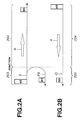
- arrows A in Figs.2A and 2B indicate the direction in which occurs the loss in the optical fiber.
- the first light transmission/reception device 201 cannot distinguish the remote-end-reflected light FX from the received light D sent from the second light transmission/reception device 202, thus producing the aforementioned problem of cross-talk.
- the amplitude of the optical sigmas and the remote-end-reflected light depends on the length of the optical fiber, the number of optical fibers to be interconnected, and on the light emission intensity of the optical transmission/reception apparatus. This poses a serious problem for the light transmission/reception apparatus of the uni-core bidirectional system in an optical fiber network constructed by optical fibers of variable lengths.
- the end faces 213a, 214a of the optical fibers 213, 214 are interconnected by the connector 215.
- a first connecting member 216 is mounted in the vicinity of the end face 213a of the optical fiber 213
- a second connecting member 217 is mounted in the vicinity of the end face 214a of the optical fiber 214 and the connecting members 216, 217 are fitted to a substantially annular fitting member 218 to interconnect the optical fibers 213, 214.
- Fig.4 shows a method of interconnection of optical fibers in which an optical adhesive 222 is used to prevent remote end reflection from occurring.
- a first connecting member 226 is mounted in the vicinity of an end face 223a of the optical fiber 223, whilst a second connecting member 227 is mounted in the vicinity of an end face 224a of the optical fiber 224, these connecting members 226, 227 being fitted to the ring-shaped fitting member 228.
- the end face 223a of the optical fiber 223 is bonded to the end face 224a of the optical fiber 224 by the optical adhesive 222 having a refractive index close to that of the cores 223b, 224b of the optical fibers 223, 224, thereby prohibiting the reflection from the remote end.
- the diameters of the core 223b, 224b of the optical fibers of quartz 223, 224 are approximately 5 ⁇ m in diameter, with the diameters thereof inclusive of clad layers 223c, 224c being approximately 125 ⁇ m.
- Embodiments of the present invention can provide optical fiber connecting method and apparatus in which optical cross-talk is prevented from occurring to assure optical communication in accordance with the uni-core bidirectional system.
- the present invention provides an optical fiber connector for interconnecting a first optical fiber and a second optical fiber including refractive index matching means having a refractive index subsequently equivalent to that of cores of first and second optical fibers, and optical fiber connecting means for interconnecting the first and second optical fibers in a state in which end faces of first and second optical fibers are contacted with refractive index matching means interposed between first and second optical fibers.
- the present invention provides a network system for interconnecting a plurality of electronic equipments including a first electronic equipment including a first optical communication circuit, an optical fiber connector, a first fiber for interconnecting first optical communication circuit and optical fiber connector, a second electronic equipment having a second optical communication circuit and a second optical fiber for interconnecting the optical fiber connector of first electronic equipment and second optical communication circuit of second electronic equipment.
- the optical fiber connector of first electronic equipment includes refractive index matching means having a refractive index substantially equivalent to that of cores of first and second optical fibers and optical fiber connecting means for interconnecting first and second optical fibers in a state in which end faces of first and second optical fibers are contacted with refractive index matching means interposed between first and second optical fibers.
- the present invention provides a electronic equipment having an optical communication circuit.
- the electronic equipment includes an optical fiber connector, and an optical fiber for interconnecting optical communication circuit and optical fiber connector.
- the optical fiber connector includes refractive index matching means, at an end of optical fiber, having a refractive index substantially equivalent to that of cores of first and second optical fibers, and optical fiber connecting means for interconnecting optical fiber and another optical fiber in a state in which end faces of optical fibers are contacted with refractive index matching means interposed between optical fibers.
- the present invention provides a method for interconnecting a first optical fiber and a second optical fiber.
- the method includes a step of interposing refractive index matching means having a refractive index substantially equivalent to that of cores of first and second optical fibers between an end face of first optical fiber and an end face of second optical fiber, and a step of interconnecting first and second optical fibers in a state in which end faces of first and second optical fibers are contacted with refractive index matching means.
- the end faces of the two optical fibers are interconnected in a state in which the end faces are contacted with refractive index matching means interposed therebetween.
- the optical fiber connector interconnects the optical fibers in a state in which the end faces are contacted with the refractive index matching means.
- optical fiber connecting apparatus product costs can be lowered without the necessity of observing machining accuracy in polishing the end faces of the optical fibers, while optical signals can be transmitted in a manner suited for optical communication, with the optical fibers being interconnected and detached from each other as desired.
- the end faces of the two optical fibers are interconnected in a state in which the end faces are contacted with refractive index matching means interposed therebetween.
- the optical fiber connector interconnects the optical fibers in a state in which the end faces are contacted with the refractive index matching means.
- Fig. 1 is a side view showing the state in which optical fibers are interconnected by associated connectors for optical fibers.
- Figs. 2A and 2B illustrate the problem of crosstalk produced in an optical fiber interconnected by associated connectors for optical fibers.
- Fig. 3 is a cross-sectional view showing a conventional optical fiber connector adapted for inhibiting Fresnel reflection.
- Fig. 4 is a cross-sectional view showing a conventional optical fiber connector adapted for interconnecting optical fibers by preventing remote end reflection by an optical adhesive for inhibiting Fresnel reflection
- Fig.5 is a cross-sectional view of the structure of an optical fiber connector according to the present invention, for showing the state in which the first connecting member is not connected to the second connecting member.
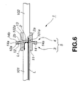
- Fig.6 is a cross-sectional view of the structure of an optical fiber connector according to the present invention, for showing the state in which the first connecting member is connected to the second connecting member.
- Fig.7 is a perspective view of an optical fiber connector, showing details of the state in which the first connecting member is not connected to the second connecting member.
- Fig.8 is a perspective view of an optical fiber connector, showing details of the state in which the first connecting member is connected to the second connecting member.
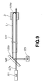
- Fig.9 shows an experimentation system constructed for evaluating the effect achieved by an optical fiber connector for comparison sake.
- Fig.10 shows an experimentation system employing the structure of the optical fiber connector, constructed for evaluating the effect achieved by an optical fiber connector
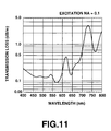
- Fig.11 is a graph showing characteristics of optical fiber loss spectrum.
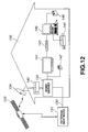
- Fig.12 shows a household network constructed by coupling optical fibers by optical fiber connectors.
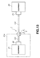
- Fig.13 is a side view showing an optical fiber connector used for interconnecting optical fibers for different equipments.
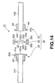
- Fig.14 is a cross-sectional view showing the structure of an optical fiber connector according to a modification of the present invention in which neither the first connecting member nor the second connecting member is connected to a third connecting member.
- Fig.15 is a is a cross-sectional view showing the structure of the optical fiber connector according to the modification of Fig.14 in which the first and second connecting members are connected to the third connecting member.
- the optical fiber connector of the present embodiment is used for making series connection of two optical fibers connected to an optical circuit.
- the optical fibers connected in the up-direction to the optical fiber connector is a so-called plastic optical fiber formed of a plastic material.
- an optical fiber connector 1 includes a refractive index matching member 2, having refractive index approximately equal to that of the cores of optical fibers 101, 102, and an optical fiber connecting portion 5 comprised of a first connecting member 3 and a second connecting member 4 interconnecting the optical fibers 101, 102, with the refractive index matching member 2 interposed between end faces 101a, 102a of the two optical fibers, with the end faces 101a, 102a being in contact with the refractive index matching member 2.
- the first connecting member 3 is shaped to be mounted on the optical fiber 101 and to have a fit on the second connecting member 4.
- the first connecting member 3 is made up of a connecting portion 11, mounted in the vicinity of the end face 101a of the optical fiber 101, and a flange-shaped protrusion 12 fitted on the second connecting member 4.
- the connecting portion 11 is substantially in the form of a cylindrical tube of an inner diameter substantially equal to the outer diameter of the optical fiber 101.
- the outer periphery of the distal end of the connecting portion 11 is provided with a flange-shaped protrusion 12.
- the flange-shaped protrusion 12 is protruded from the outer periphery of the connecting portion 11 so as to have a fit on the second connecting member 4.
- the flange-shaped protrusion 12, protruded from the outer periphery of the connecting portion 11, is of a substantially flat disc shape, and is connected as-one to the connecting portion 11.
- the first connecting member 3, constructed as described above, is loaded in the vicinity of the end face 101 a of the optical fiber 101. Specifically, the first connecting member 3 is connected in the vicinity of the end face 101 a of the optical fiber 101 in such a manner that an end face 11a thereof is receded slightly from the end face 101a of the optical fiber 101, that is that the end face 101a of the optical fiber 101 is protruded slightly, as shown in Fig.3.
- the second connecting member 4 is shaped so that the optical fiber 102 is loaded thereon and so that the first connecting member 3 has a fit thereon.
- the second connecting member 4 is made up of a connecting portion 13 loaded in the vicinity of the end face 102a of the optical fiber 102 and a flange-shaped fitting portion 14 on which is fitted the flange-shaped protrusion 12 of the first connecting member 3.
- the connecting portion 13 is in the shape of substantially a cylindrical tube having an inner diameter substantially equal to the outer diameter of the optical fiber 101.
- a flange-shaped fitting portion 14 is formed on the outer periphery of the distal end of the connecting portion 13.
- the connecting portion 13 has a mounting portion 13a on which to mount the refractive index matching member 2.
- the mounting portion 13a is formed as a shoulder in an inner rim of an end face of the connecting portion 13.
- the flange-shaped fitting portion 14 is shaped to permit the first connecting member 3 to be fitted thereon. Specifically, the flange-shaped fitting portion 14 is formed as-one with the connecting portion 13 on its outer periphery with an engaging portion 14a.
- the engaging portion 14a is formed on the outer periphery of a sidewall section 14b comprised of a substantially flat disc shape and is protruded forwards at right angles to the sidewall section 14b.
- a groove 14c engaged with an engaging portion 12a of the flange-shaped protrusion 12.
- the groove 14a is substantially in the shape of a recessed torus.
- the first connecting member 3 By having the engaging portion 12a of the first connecting member 3 formed substantially as a convex torus and by having the groove 14a of the second connecting member 4 formed substantially as a recessed torus, the first connecting member 3 can be easily mounted on or dismounted from the second connecting member 4.
- the refractive index matching member 2 has its surface 2a configured as a disc.
- the refractive index matching member 2 is formed of an elastic material having a refractive index substantially equal to that of the cores of the optical fibers 101, 102. Specifically, the refractive index matching member 2 is formed of silicone.
- the refractive index matching member 2 has the first surface 2a as a surface to which is connected the end face 102a of the optical fiber 102 loaded on the second connecting member 4.
- the refractive index matching member 2 also has a second surface 2b facing the first surface 2a and to which is connected the end face 101a of the optical fiber 101 in the interconnected state of the first connecting member 3 and the second connecting member 4.
- the refractive index matching member 2 is mounted on the mounting portion 13a of the connecting portion 13.
- the first connecting member 3 is connected to the second connecting member 4 to connect the end faces 101a, 102a of the optical fibers 101, 102, loaded on the connecting members 3, 4, to the refractive index matching member 2, with the end face 101a facing the end face 102a. Since the refractive index matching member 2 has the refractive index equal to that of the optical fibers 101, 102, it is possible to suppress Fresnel reflection on the end faces 101a, 102a of the optical fibers 101, 102.
- the end face 101a of the optical fiber 101 is protruded from the end face 11a of the first connecting member 3, so that, when the first connecting member 3 is connected to the second connecting member 4, and the engaging portion 12a of the first connecting member 3 is retained by the engaging portion 14a of the second connecting member 4, the faces 2a, 2b of the refractive index matching member 2 tend to be abutted against the end faces 101 a, 102a of the optical fibers 101, 102, under the force of elasticity of the refractive index matching member 2.
- the adhesion between the forward ends 101a, 102a of the optical fibers 101, 102 and the end faces 2b, 2a of the refractive index matching member 2 is increased. Since the first connecting member 3 and the second connecting member 4 of the optical fiber connector 1 are detachable from each other, it is possible to connect or detach the optical fibers 101, 102 to or from each other as desired.
- the refractive index matching member 2 is interposed between the end faces 101a, 102a of the optical fibers 101, 102, it is possible to prevent an air layer from being interposed between the end faces 101a, 102a of the optical fibers 101, 102 by improving contact tightness.
- the first connecting member 3 can be detachably fitted relative to the second connecting member 4.
- At least the flange-shaped protrusion 12 in the first connecting member 3 and at least the flange-shaped fitting portion 14 in the second connecting member 4 may be formed of an elastic material. By so doing, the first connecting member 3 and the second connecting member 4 can be easily connected or detached relative to each other.
- the flange-shaped protrusion 12 need not be formed as-one with the connecting portion 11, whilst the flange-shaped fitting portion 14 need not be formed as-one with the connecting portion 13. That is, the flange-shaped protrusion 12 and the flange-shaped fitting portion 14 may be formed as separate members from the connecting portions.
- the meritorious effect of the use of the refractive index matching member 2 is hereinafter explained.
- light is reflected on an interface between two mediums having different refractive index values.
- the refractive index n1 and the refractive index n2 represent the refractive indices of the core of the optical fiber 101 and the air, respectively.
- the reflectance is 3.9%.
- the light L1 reflected by the end face of the optical fiber 101 at this time represents the cross-talk.
- the reflectance can be reduced to 0.01% by using silicone having a refractive index to the light with a wavelength of 650 nm of 1.52 as a material of the refractive index matching member 2, and by tightly contacting the end face 101a of the optical fiber 101 with the refractive index matching member 2 to eliminate an air layer between the end face 101a and the surface 2b of the refractive index matching member 2.
- the Fresnel reflection on the interface between the end face 102a and the air can be reduced by tightly contacting the end face 102a of the optical fiber 102 with the refractive index matching member 2.
- the reduction in the Fresnel reflection leads not only to reduced crosstalk but also to improved coupling efficiency between the optical fibers 101 and 102.
- the refractive index matching member 2 having the reflectance R satisfying the equation (4), it is possible to have communication by optical signals with the performance required by the optical communication circuit.
- the end face 101a of the optical fiber 1 is opened to face the outside, so that it is contacted with air.
- the end face 101a of the optical fiber 101 is tightly contacted with the refractive index matching member 2.
- an optical absorber 124 is bonded to the back side of the refractive index matching member 2 to which is not bonded the end face 101a of the optical fiber 101.
- the refractive index matching member 2 is formed of silicone.
- the commercially available silicone with a refractive index of 1.52, a tensile strength of 2 kgf/cm 2 and an elongation of 50% may be used.
- the tensile strength denotes the rubber characteristics as defined by the JIS K 6250 measurement method.
- the elongation denotes the length elongated on the occasion of the tensile strength test.
- the elongation of 50% indicates that the sample length has been extended in an amount of 50% of the initial length.
- the refractive index matching member 2 formed of silicone having these characteristics, has pliability sufficient for the refractive index matching member 2 to be deformed into tight contact with the end faces 101a, 101b of the optical fibers 101, 102. If the mounting or dismounting with respect to the optical fibers is repeated, the optical fibers suffer no change in refractive index characteristics.
- the two experimentation systems are provided with a laser diode (LD) 121 as a light source and a beam splitter (BS) 122 for reflecting the light reflected by the end face 101a of the optical fiber 101 to a light-receiving element (PLASMA DISCHARGE), as shown in Figs.9 and 10.
- the laser diode 121 exits the light with an oscillation wavelength of 650 nm.
- the optical fiber 101 used for measurement is formed of plastics and has characteristics shown in Table 1 and the loss spectrum shown in Fig.11. outer diameter of optical fiber 100 ⁇ m outer shape of coating 2.2 mm material type of coating polyethylene transmission loss 14dB/100m band 160 MHz@100m refractive index core 1.492 cladding 1.456
- the outgoing light LDL from the laser diode 121 is transmitted through the beam splitter 122 to fall on the optical fiber 101.
- the light incident on the optical fiber 101 is reflected by the end face 101 a of the optical fiber 101 and thence proceeds as the reflected light L1 towards a reflecting surface 122a of a beam splitter (BS) 122.
- the reflected light L1 is reflected by the reflecting surface 122a of the beam splitter 122 to fall on a light receiving element 123.
- the present optical fiber connector 1 is used for constructing a home network as shown in Fig.12.
- a house 130 is connected via a communication cable 132 or an artificial satellite 133 with an external network 131.
- In the house 130 are arranged electrical appliances, information equipments and so forth.
- a home server 134 serves for storing the information from the external network 131. The appliances or equipments in a home can have access to the home server 134 to download the latest information promptly.
- a set top box 140 serves for processing; the information received via an antenna 134 from an artificial satellite 133.
- the equipments installed in the house 130 may be exemplified by a TV receiver 141, a video camera 142, a video recorder 143, a printer/facsimile 144, a computer 145, a digital still camera 146, and so forth.
- the optical fiber connector 1 can be used if the home network constructed by these plural electronic equipments is constructed by an optical fiber.
- the home network equipments can be connected to the home network via optical transmission/reception devices 22, 24 shown for example in Fig.13 to construct the home network.
- the optical transmission/reception devices 22, 24 enable bidirectional optical communication between the equipments 21 and 23, and are used as a transmission channel for optical signals.
- the equipments 21 and 23 are the aforementioned electronic equipments or information equipments, such as the video recorder or a computer, as described above.
- the electronic equipments each include a transmission/reception device 22 in the inside of the casing 21 a and a connecting portion on the outer surface of the casing 21 a adapted to be connected to an optical fiber 102 of another equipment 23. That is, the optical fiber 102 extended from the equipment 23 as a counterpart of the optical communication is longer in length than the length of the optical fiber 101 extended in the inside of the casing 21 a from the optical transmission/reception device 22 to the connecting portion of the casing 21a.
- the optical fiber connector 1 can be used in a connecting portion of the optical fiber arranged on an outer surface of the casing 21a.
- optical fiber connector 1 By using the optical fiber connector 1 in such home network, it is possible to prevent crosstalk between the variable equipment, such as electronic equipments making up the home network, to effect transmission/reception of optical signals.
- the refractive index matching member 2 is built into the optical fiber connector 1.
- the present invention may, however, be applied to an embodiment in which the refractive index matching member 2 is designed as an independent member.
- an optical fiber connector 31 is made up of a refractive index matching member 32 and an optical fiber connecting potion 36, made up of a first connecting member 33, a second connecting member 34 and a third connecting member 35, and which is adapted for arranging the end faces 101a, 102a of the optical fibers 101, 102 so as to face each other on either sides of the refractive index matching member 32 and for bringing the end faces 101 a, 102a in this state into contact with the respective sides of the refractive index matching member 32, as shown in Figs.14 and 15, the refractive index matching member 32 can be made dismountable.
- the refractive index matching member 32 is formed of a material similar to that of the refractive index matching member 2.
- the optical fiber connector 31 interconnects the optical fibers 101, 102 by fitting the first and second connecting members 33, 34 to the third connecting member 35 carrying the refractive index matching member 32.
- the first and second connecting members 33, 34 are constructed similarly to the first connecting member 3 of the above-described optical fiber connector 1.
- the first connecting member 33 is contoured so as to be loaded on the optical fiber 101 and so as to have a fit on the third connecting member 35.
- the first connecting member 33 is made up of a connecting member 41, mounted in the vicinity of the end face 101a of the optical fiber 101 and a flange-shaped protrusion 42 fitted to the third connecting member 35.
- the connecting member 41 is substantially in the shape of a cylindrical tube the inner diameter of which is substantially equal to the outer diameter of the optical fiber 101.
- On the outer periphery of the distal end of the connecting member 41 is formed the flange-shaped protrusion 42.
- the flange-shaped protrusion 42 is protruded from the outer periphery of the connecting member 41 so as to have a fit on the third connecting member 35.
- the flange-shaped protrusion 42 protruded from the outer periphery of the connecting member 41, is formed to a substantially flat disc and formed as-one with the connecting member 41.
- the outer rim of the flange-shaped protrusion 42 is an engaging portion 42a engaged with the third connecting member 35.
- the outer rim of the flange-shaped protrusion 42 is formed to, for example, a substantially convexed torus shape.
- the flange-shaped protrusion 42 is formed of an elastic material.
- the flange-shaped protrusion 42 need not necessarily be formed as-one with the connecting member 41 since it may be constructed as a separate member from the connecting member 41.
- the first connecting member 33 constructed as described above, is loaded in the vicinity of the end face 101a of the optical fiber 101 so that the end face 41a is slightly receded from the end face 101a of the optical fiber 101, that is so that the end face 101a of the optical fiber 101 is protruded from the end face 41a.
- the second connecting member 34 is constructed to substantially the same shape as the first connecting member 33. That is, the second connecting member 34 is shaped so that it can be loaded on the optical fiber 102 and so that it will have a fit on the third connecting member 35. Specifically, the second connecting member 34 is made up of a connecting portion 43 and a flange-shaped protrusion 44 fitted to the third connecting member 35.
- the connecting portion 43 is substantially in the shape of a cylindrical tube the inner diameter of which is substantially equal to the outer diameter of the optical fiber 102.
- On the outer periphery of the distal end of the connecting member 43 is formed a flange-shaped protrusion 4.
- the flange-shaped protrusion 44 is protruded from the outer periphery of the connecting member 43 so as to have a fit on the third connecting member 35.
- the flange-shaped protrusion 44 protruded from the outer periphery of the connecting member 43, is formed to a substantially flat disc and formed as-one with the connecting member 43.
- the outer rim of the flange-shaped protrusion 43 is an engaging portion 44a adapted to be engaged with the third connecting member 35.
- the outer rim of the flange-shaped protrusion 44 is formed to, for example, a substantially convexed torus shape.
- the flange-shaped protrusion 44 is formed of an elastic material.
- the flange-shaped protrusion 44 need not necessarily be formed as-one with the connecting portion 43 since it may be constructed as a separate member from the connecting portion 43.
- the second connecting member 34 constructed as described above, is loaded in the vicinity of the end face 102a of the optical fiber 102 so that the end face 43a is slightly receded from the end face 102a of the optical fiber 102, that is so that the end face 102a of the optical fiber 102 is protruded from the end face 102a.
- the third connecting member 35 to which are fitted the first and second connecting members 33,34, is provided with a mounting portion 35a, to which is fitted the refractive index matching member 32.
- the third connecting member 35 is also provided with engaging portions 35b, 35c, to which are fitted the first and second connecting members 33, 34, and is formed to substantially a disc shape.
- the mounting portion 35a is substantially in the form of a flat disc and has respective surfaces 32a, 32b at mid portions thereof, so that these surfaces 32a, 32b face the end faces 102a, 101a of the optical fibers 102, 101, respectively.
- the engaging portions 35b, 35c are formed on the outer periphery of the mounting portion 35a to protrude towards the back sides of the optical fibers 101, 102 subsequently at right angles to the mounting portion 35a.
- a groove 35d engaged by the engaging portion 42a of the flange-shaped protrusion 42.
- the groove 35d is formed to substantially the shape of a recessed torus surface.
- a groove 35e engaged by the engaging portion 44a.
- the groove 35e is formed to substantially the shape of a recessed torus surface.
- the optical fiber connector 31 constructed as described above, is arranged by fitting the first connecting member 33 and the second connecting member 34 on the third connecting member 35, for connecting the end faces 101a, 102a of the optical fibers 101, 102 loaded on the first and second connecting members 33, 34, respectively, to the refractive index matching member 32, with the end faces 101a, 102a facing each other. Since the refractive index matching member 32 has the refractive index equal to that of the optical fibers 101, 102, it becomes possible to suppress the Fresnel reflection occurring on the end faces 101a, 102a of the optical fibers 101, 102.
- the refractive index matching member 32 can be exchanged easily, because the third connecting member 35 can be mounted in position or dismounted easily.
- optical fiber connector of the present invention can be applied to all optical guide paths as a device for prohibiting Fresnel reflection of the optical guide paths.
- the foregoing description also has been directed to the application of the optical fiber connector 1 to LAN (local area network) in the household, that is in a home network or in an office LAN.
- LAN local area network
- the present invention is, however, not limited thereto and can also be applied to the communication system for exchanging variable information in mobile bodies, such as cars or aircraft.
- the wavelength of the light beams, the refractive index of which is to be matched is set to 650 nm. However, it is of course possible to use other wavelength ranges.
Landscapes
- Physics & Mathematics (AREA)
- General Physics & Mathematics (AREA)
- Optics & Photonics (AREA)
- Optical Couplings Of Light Guides (AREA)
- Mechanical Coupling Of Light Guides (AREA)
Applications Claiming Priority (2)
| Application Number | Priority Date | Filing Date | Title |
|---|---|---|---|
| JP36800198 | 1998-12-24 | ||
| JP10368001A JP2000193850A (ja) | 1998-12-24 | 1998-12-24 | 光ファイバ連結装置及び光ファイバ連結方法 |
Publications (2)
| Publication Number | Publication Date |
|---|---|
| EP1014128A2 true EP1014128A2 (fr) | 2000-06-28 |
| EP1014128A3 EP1014128A3 (fr) | 2004-03-24 |
Family
ID=18490732
Family Applications (1)
| Application Number | Title | Priority Date | Filing Date |
|---|---|---|---|
| EP99310465A Withdrawn EP1014128A3 (fr) | 1998-12-24 | 1999-12-23 | Dispositif de connexion de fibres optiques, système de réseau et procédé de connexion de fibres optiques |
Country Status (6)
| Country | Link |
|---|---|
| US (1) | US6443628B1 (fr) |
| EP (1) | EP1014128A3 (fr) |
| JP (1) | JP2000193850A (fr) |
| KR (1) | KR20000048353A (fr) |
| CN (1) | CN1261677A (fr) |
| SG (1) | SG81341A1 (fr) |
Families Citing this family (7)
| Publication number | Priority date | Publication date | Assignee | Title |
|---|---|---|---|---|
| JP3750925B2 (ja) | 2000-12-01 | 2006-03-01 | シャープ株式会社 | 光ファイバーケーブルの遠端反射率の測定方法 |
| CN101506706B (zh) * | 2006-06-30 | 2012-05-30 | 莫列斯公司 | 光纤连接器中位于光纤端部的聚合物层及相关方法 |
| JP5616601B2 (ja) * | 2008-09-17 | 2014-10-29 | カール・ツァイス・エスエムティー・ゲーエムベーハー | 光学装置用の接続装置 |
| US8554039B2 (en) * | 2009-10-13 | 2013-10-08 | Corning Incorporated | Buffered large core fiber |
| US20110091166A1 (en) * | 2009-10-15 | 2011-04-21 | Seldon David Benjamin | Fiber Optic Connectors and Structures for Large Core Optical Fibers and Methods for Making the Same |
| US8998502B2 (en) | 2010-09-03 | 2015-04-07 | Corning Incorporated | Fiber optic connectors and ferrules and methods for using the same |
| CN102360101A (zh) * | 2011-11-08 | 2012-02-22 | 江苏宇特光电科技有限公司 | 一种光纤活动连接器的制作及耦合方法 |
Family Cites Families (7)
| Publication number | Priority date | Publication date | Assignee | Title |
|---|---|---|---|---|
| US4512630A (en) * | 1975-11-11 | 1985-04-23 | At&T Bell Laboratories | Optical fiber connector |
| US4087158A (en) * | 1976-12-06 | 1978-05-02 | The United States Of America As Represented By The Secretary Of The Navy | Low-loss single filament fiber optic connector with three concentric tapered members for each filaments |
| FR2386060A1 (fr) * | 1977-03-28 | 1978-10-27 | Connexion Ste Nle | Connecteur a tampon interfacial en elastomere pour conducteurs optiques |
| US4186998A (en) * | 1978-06-14 | 1980-02-05 | The Deutsch Company Electronic Components Division | Optical interconnecting device having tapered surfaces |
| US4255016A (en) * | 1979-07-02 | 1981-03-10 | International Telephone And Telegraph Corporation | Fiber optic connector |
| US4991929A (en) * | 1989-05-12 | 1991-02-12 | Amp Incorporated | Index matching film |
| SE9504206D0 (sv) | 1995-11-24 | 1995-11-24 | Pharmacia Ab | Optical coupling device and method for its production |
-
1998
- 1998-12-24 JP JP10368001A patent/JP2000193850A/ja not_active Withdrawn
-
1999
- 1999-12-22 US US09/469,696 patent/US6443628B1/en not_active Expired - Fee Related
- 1999-12-22 SG SG9906491A patent/SG81341A1/en unknown
- 1999-12-23 EP EP99310465A patent/EP1014128A3/fr not_active Withdrawn
- 1999-12-23 KR KR1019990060840A patent/KR20000048353A/ko not_active Withdrawn
- 1999-12-24 CN CN99122982A patent/CN1261677A/zh active Pending
Also Published As
| Publication number | Publication date |
|---|---|
| SG81341A1 (en) | 2001-06-19 |
| EP1014128A3 (fr) | 2004-03-24 |
| US6443628B1 (en) | 2002-09-03 |
| KR20000048353A (ko) | 2000-07-25 |
| CN1261677A (zh) | 2000-08-02 |
| JP2000193850A (ja) | 2000-07-14 |
Similar Documents
| Publication | Publication Date | Title |
|---|---|---|
| US7556440B2 (en) | Dual-lensed unitary optical receiver assembly | |
| CN100545687C (zh) | 双向光学收发器 | |
| US8315492B2 (en) | Fiber connector module including integrated optical lens turn block and method for coupling optical signals between a transceiver module and an optical fiber | |
| US7965913B2 (en) | Optical star coupler | |
| US10012793B2 (en) | Asymmetric optical mixer system | |
| US8244085B2 (en) | Optical transceiver interface for multimode fibers | |
| US4955014A (en) | Broadband optical communication system, particularly in the subscriber area | |
| EP1561133A1 (fr) | Lentilles optiques | |
| EP1014128A2 (fr) | Dispositif de connexion de fibres optiques, système de réseau et procédé de connexion de fibres optiques | |
| US7206140B2 (en) | Lens, lens array and optical receiver | |
| US6478479B1 (en) | Optical connector module with optical fibers for connecting optical module and optical fiber connector | |
| WO2004075422A2 (fr) | Module comprenant deux emetteurs-recepteurs optiques bidirectionnels | |
| Nawata | Multimode and single-mode fiber connectors technology | |
| US7016559B2 (en) | Optical transmitter-receiver and optical fiber | |
| US7354201B2 (en) | Devices for reflection reduction in optical devices | |
| JP2020522742A (ja) | 光電子モジュール用のコネクタアセンブリ | |
| US20050220410A1 (en) | Low reflectance optical coupling | |
| US7665907B2 (en) | Optical connector assembly | |
| WO2020153238A1 (fr) | Connecteur optique, câble optique et appareil électronique | |
| JP2005318532A (ja) | 光信号伝送システム及びcatv伝送システム | |
| Ajemian | Transmission Techniques: Fiber Optics | |
| JPH11352363A (ja) | 光送受信装置と光送受信装置の組み立て方法 | |
| JP2024003344A (ja) | 光送信器及び光伝送システム | |
| WO2005096525A1 (fr) | Systeme de transmission de signaux optiques et systeme de transmission de teledistribution | |
| HK40039704A (en) | Optical subassembly structure |
Legal Events
| Date | Code | Title | Description |
|---|---|---|---|
| PUAI | Public reference made under article 153(3) epc to a published international application that has entered the european phase |
Free format text: ORIGINAL CODE: 0009012 |
|
| AK | Designated contracting states |
Kind code of ref document: A2 Designated state(s): AT BE CH CY DE DK ES FI FR GB GR IE IT LI LU MC NL PT SE |
|
| AX | Request for extension of the european patent |
Free format text: AL;LT;LV;MK;RO;SI |
|
| PUAL | Search report despatched |
Free format text: ORIGINAL CODE: 0009013 |
|
| AK | Designated contracting states |
Kind code of ref document: A3 Designated state(s): AT BE CH CY DE DK ES FI FR GB GR IE IT LI LU MC NL PT SE |
|
| AX | Request for extension of the european patent |
Extension state: AL LT LV MK RO SI |
|
| AKX | Designation fees paid | ||
| REG | Reference to a national code |
Ref country code: DE Ref legal event code: 8566 |
|
| STAA | Information on the status of an ep patent application or granted ep patent |
Free format text: STATUS: THE APPLICATION IS DEEMED TO BE WITHDRAWN |
|
| 18D | Application deemed to be withdrawn |
Effective date: 20040925 |