EP1014144A1 - Neigungskorrektur zwischen einem Linsenraster und einem Referenzstrahl - Google Patents
Neigungskorrektur zwischen einem Linsenraster und einem Referenzstrahl Download PDFInfo
- Publication number
- EP1014144A1 EP1014144A1 EP99203952A EP99203952A EP1014144A1 EP 1014144 A1 EP1014144 A1 EP 1014144A1 EP 99203952 A EP99203952 A EP 99203952A EP 99203952 A EP99203952 A EP 99203952A EP 1014144 A1 EP1014144 A1 EP 1014144A1
- Authority
- EP
- European Patent Office
- Prior art keywords
- light
- lenticular material
- lenticular
- cylindrical lenses
- platen
- Prior art date
- Legal status (The legal status is an assumption and is not a legal conclusion. Google has not performed a legal analysis and makes no representation as to the accuracy of the status listed.)
- Granted
Links
- 239000000463 material Substances 0.000 title claims abstract description 126
- 238000012937 correction Methods 0.000 title claims abstract description 7
- 238000001514 detection method Methods 0.000 title description 6
- 239000000839 emulsion Substances 0.000 claims abstract description 26
- 230000035945 sensitivity Effects 0.000 claims abstract description 7
- 238000000034 method Methods 0.000 claims description 29
- 239000012780 transparent material Substances 0.000 claims description 4
- 235000010627 Phaseolus vulgaris Nutrition 0.000 claims description 2
- 244000046052 Phaseolus vulgaris Species 0.000 claims description 2
- 238000010586 diagram Methods 0.000 description 7
- 230000000694 effects Effects 0.000 description 6
- 238000004519 manufacturing process Methods 0.000 description 6
- 238000006073 displacement reaction Methods 0.000 description 3
- 230000010363 phase shift Effects 0.000 description 3
- 239000011521 glass Substances 0.000 description 2
- 238000012545 processing Methods 0.000 description 2
- 230000007723 transport mechanism Effects 0.000 description 2
- 230000003750 conditioning effect Effects 0.000 description 1
- 230000009977 dual effect Effects 0.000 description 1
- 210000000887 face Anatomy 0.000 description 1
- 238000013507 mapping Methods 0.000 description 1
- 230000003287 optical effect Effects 0.000 description 1
- 230000001151 other effect Effects 0.000 description 1
- 238000012552 review Methods 0.000 description 1
- 239000000523 sample Substances 0.000 description 1
Images





Classifications
-
- G—PHYSICS
- G02—OPTICS
- G02B—OPTICAL ELEMENTS, SYSTEMS OR APPARATUS
- G02B27/00—Optical systems or apparatus not provided for by any of the groups G02B1/00 - G02B26/00, G02B30/00
- G02B27/0025—Optical systems or apparatus not provided for by any of the groups G02B1/00 - G02B26/00, G02B30/00 for optical correction, e.g. distorsion, aberration
- G02B27/0031—Optical systems or apparatus not provided for by any of the groups G02B1/00 - G02B26/00, G02B30/00 for optical correction, e.g. distorsion, aberration for scanning purposes
-
- G—PHYSICS
- G02—OPTICS
- G02B—OPTICAL ELEMENTS, SYSTEMS OR APPARATUS
- G02B30/00—Optical systems or apparatus for producing three-dimensional [3D] effects, e.g. stereoscopic images
- G02B30/20—Optical systems or apparatus for producing three-dimensional [3D] effects, e.g. stereoscopic images by providing first and second parallax images to an observer's left and right eyes
- G02B30/26—Optical systems or apparatus for producing three-dimensional [3D] effects, e.g. stereoscopic images by providing first and second parallax images to an observer's left and right eyes of the autostereoscopic type
- G02B30/27—Optical systems or apparatus for producing three-dimensional [3D] effects, e.g. stereoscopic images by providing first and second parallax images to an observer's left and right eyes of the autostereoscopic type involving lenticular arrays
-
- Y—GENERAL TAGGING OF NEW TECHNOLOGICAL DEVELOPMENTS; GENERAL TAGGING OF CROSS-SECTIONAL TECHNOLOGIES SPANNING OVER SEVERAL SECTIONS OF THE IPC; TECHNICAL SUBJECTS COVERED BY FORMER USPC CROSS-REFERENCE ART COLLECTIONS [XRACs] AND DIGESTS
- Y10—TECHNICAL SUBJECTS COVERED BY FORMER USPC
- Y10S—TECHNICAL SUBJECTS COVERED BY FORMER USPC CROSS-REFERENCE ART COLLECTIONS [XRACs] AND DIGESTS
- Y10S430/00—Radiation imagery chemistry: process, composition, or product thereof
- Y10S430/147—Lenticular
Definitions
- the invention relates generally to the field of manufacturing lenticular images and more particularly to detecting and measuring the relative skew of a writing laser beam to lenticular material which is used for producing the lenticular images. More specifically, the invention relates to the detection and correction of any skew between the writing laser beam and the lenticules as the material is transported in a scanning laser printer.
- Lenticular images include an array of cylindrical lenses in a lenticular material and a sequence of spatially multiplexed images that are viewed through the lenticular material so that different ones of the multiplexed images are viewed at different angles by the viewer.
- One image effect produced by the lenticular image is a depth or stereoscopic image where the lenticules are oriented vertically and one eye views one image of a stereo pair or sequence from one angle and the other eye views another image from the stereo pair.
- Another image effect is a motion image where different images in a motion image sequence are viewed by both eyes, while changing the angle at which the image is viewed.
- the lenticules are oriented in the horizontal direction and the lenticular material is rotated about the long axis of the lenticules.
- Other effects that combine these two effects, or form collages of unrelated images that can be viewed from different viewing angles can be provided.
- the image that is exposed on the lenticular material must be very precisely positioned under each lenticule. If the separate image lines produced by the writing laser beam of the laser scanner and the lenticules on the material are not aligned parallel, the resulting skew misalignment will degrade the image quality. There is a need therefore for an improved manufacturing process for making lenticular image products from lenticular material of the type having a lenticular lens array coated with photographic emulsion.
- a lenticular image product is formed from a lenticular material having an array of cylindrical lenses and a photographic emulsion coated thereon, by scanning the lenticular material with an intensity modulated first beam of light in a direction parallel to the long axes of the cylindrical lenses to form a latent lenticular image in the photographic emulsion.
- a second beam of light having wavelength outside of the range of sensitivity of the photographic emulsion is focused into a spot smaller than the pitch of the cylindrical lenses onto the lenticular material.
- the lenticular material is moved through the beam to provide a page scan motion across the short axes of the lenticules of the material and to modulate the angle of reflection or refraction of the second beam of light caused by the lenticules.
- the position of the angularly modulated second beam of light is sensed at two separated points along the long axes of a lenticular and the sensed positions are used to control the rotational position of a pivoting cylinder mirror assembly.
- the invention provides an accurate method for either mapping lenticular skew or detecting skew variations which can be compensated in a laser printer, thereby enabling efficient production of high quality lenticular image products using lenticular material having photographic emulsion coated thereon.
- lenticular image production apparatus 10 includes a platen 12 for supporting lenticular material 14.
- Lenticular material 14 is placed with the lenticules down in the top of platen 12 so that the emulsion side 13 of the lenticular material 14 faces up. Further, the lenticular material 14 is made to overhang the platen 12 on both sides allowing fixed detectors 44 and 44a to be placed under the overhung edges of lenticular material 14.
- a suitable mounting structure (not shown) that fixedly mounts detectors 44 and 44a while transport platen 12 and lenticular material 14 move is provided to hold detectors 44 and 44a under the area where lenticular material 14 is exposed.
- the lenticular material 14 is transported by platen 12 in the direction of arrow A by a linear transport system that is suitably driven, typically by a motor system (not shown) such as a direct drive linear motor or leadscrew. These drive system are well understood and known in the art.
- the lenticular material 14 is exposed with a writing laser beam 22 from a modulated laser 24.
- the writing laser beam 22 is focused onto a scanning polygon 26 by optics 28.
- the scanning polygon 26 rotates in direction C causing the reflected writing laser beam 22 to scan in the D direction.
- the writing laser beam 22 is reflected from a cold mirror (reflects visible light and transmits infra red light) 32 onto pivotable cylinder mirror 34. Cylinder mirror 34 focuses the writing laser beam 22 onto the surface 13 of the lenticular material 14 thereby exposing the color photographic emulsion.
- An infrared laser 36 located at a distance from the surface of the material identical to the distance to the scanning face of the polygon 26, forms a second beam of light 38, of a wavelength that can be transmitted through and which does not expose the lenticular material 14.
- the second beam of light is reflected by a IR turning mirror 40 through cold mirror 32 onto cylinder mirror 34.
- Cylinder mirror 34 focuses the second beam 38 onto the surface 13 of the lenticular material 14 in a line or two spots narrower than the width of a lenticule.
- Fixed detectors 44 and 44a are sensitive to the wavelength of second beam 38 and made insensitive to writing laser beam 22 by suitable filters placed over each detector during their manufacturing process.
- Second beam 38 passes through lenticular material 14 and is refracted by the lenticules of lenticular material 14 and impinge on fixed detectors 44 and 44a on either side of platen 12. Thus, the position of second beam 38 is sensed by detectors 44 and 44a relative to the lenticules of lenticular material 14.
- Cylinder mirror 34 is mounted so that it is rotatable about a pivot axis 35 in the direction arrow E at the center of the scan line of writing laser beam 22.
- the pivoting cylinder mirror 34 rotates both the first and second laser beams 22 and 38 about pivot axis 35 and assures that the line of second beam 38 and the scan line of writing laser beam 22 are maintained parallel.
- the scanning polygon 26 works in conjunction with the pivoting cylinder mirror 34 to cause the writing laser beam 22 to scan the lenticular material in the direction of arrow B, parallel to the long cylindrical axes of the lenticules of lenticular material 14.
- the motion of the lenticular material 14 caused by platen 12 in the direction of arrow A provides scanning in the orthogonal or page scan direction.
- pivoting mirror 34 is measured by position sensor 20 whose moving member 21 is fixedly mounted to the end portion of pivoting mirror 34.
- This sensor may be of any suitable type of position sensor known and employed in the art such as an LVDT, capacitive probe or potentiometer.
- a means for displacing or rotating the pivoting mirror 34 At the other end of pivoting mirror 34 is attached a means for displacing or rotating the pivoting mirror 34.
- a D.C. motor 19 and leadscrew 18 are employed to produce a controlled displacement of the end portion of pivoting mirror 34 in the direction of arrow F, and thus an angular displacement E about pivot axis 35.
- pivoting mirror 34 can be accurately controlled to change the angle of writing laser beam 22 and second beam 38 with respect to the lenticules on lenticular material 14 and therefore minimize any skew misalignment between them.
- Fig. 2 illustrates an alternate method for aligning a writing laser beam 22 and lenticular material 14.
- the optical elements described and depicted in Fig. 1 are the same but pivoting cylinder mirror 34 is held in a cylinder mirror fixed mount 27.
- Motor 19 and leadscrew 18 along with sensor 20 and its moving member 21 are not used.
- Movable platen 12 is mounted on a rotating mechanical stage 1 which is fixedly mounted on a rotational stage base 23.
- Rotational stage base 23 is transported in the direction A by the same type of linear transport means discussed in Fig. 1.
- Rotational skew alignment of writing laser beam 22 to the lenticules of lenticular material 14 is accomplished by the rotational movement of rotating mechanical stage 17 in the indicated direction G. Movement of rotating mechanical stage 17 in the indicated direction G produces rotational movement of platen 12 and lenticular material 14 about the rotating mechanical stage axis 25 of rotating mechanical stage 17. Movement of lenticular material 14 about axis 25 changes the relative angular position of the lenticules of lenticular material 14 and writing laser beam 22 and second beam 38 is detected by fixedly mounted detectors 44 and 44a. Thus, the angular skew alignment of the lenticules of lenticular material 14 and writing laser beam 22 can be sensed and corrected to a minimum or any desired angular skew alignment by this means.
- the means for rotational movement of rotating mechanical stage 17 can be any of the known means used in the art, such as: motor driven worm and pinion gear, lever arm or manual adjustment.
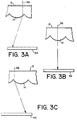
- Fig. 3 illustrating how the lenticular material deflects the beam 38 of infra red light as it passes through different portions of one of the lenticular lenses in the lenticular material 14.
- Beam 38 is focused onto and is transmitted through the top layer 13 composed of a color photographic emulsion.
- the beam 38 first encounters a lenticule, as shown in the illustration (A) on the left of Fig. 2, it is refracted at a large angle to the left and impinges on the left side of the position sensing detector 44. The angle depends upon the position of the lenticule with respect to the beam 38.
- the position detector 44 maybe, for example, a PSD S3932 position sensitive detector available from Hamamatsu Photonics KK, Hamamatsu, Japan. However, any suitable photosensor means may be employed to detect the position of beam 38, including: split cell detectors, CCD image sensors and any other photosensors capable of sensing a relative position change of a spot or line of light.
- FIG. 4 there is shown further details of the functionality of the position sensing detector 44.
- the lenticular material 14 is moved relative to the beam 38 by a transport mechanism (not shown) in direction A.
- the centroid of the exiting beam 33 is axially displaced from the original beam 38 by a distance d. This distance d is measured by a position sensing detector 44.
- An output signal 48 is generated as the centroid of the exiting beam 33 is axially displaced from the original beam 38 by a distance d. Waveform 48 produced by position detector 44 is shown in Fig. 4.
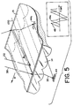
- Fig. 5 where the skew misalignment of the writing laser beam 22 and second beam 38 with respect to the lenticules is shown.
- Position sensing detectors 44 and 44a are shown in the correct orientation of detecting this skew misalignment.
- the second beam 38 is transmitted through the lenses of the lenticules and refracted resulting in the generation of output signals 48 and 48a by detectors 44 and 44a. Due to the fact that the second beam 38 is misaligned relative to the long axis of the lenticule 100, the position of the refracted beam 33 is different at each detector, causing waveforms 48 and 48a to be positionally out of phase.
- FIG. 6 depicts a top view of a lenticule and second beam 38 that creates the resulting output waveforms 48 and 48a from position sensing detectors 44 and 44a for three cases of skew alignment.
- Fig. 6a shows a clockwise skew misalignment between the second beam 38 and the long axis 100 of the lenticule. This misalignment is measured by the relative phase shift between the output signals 48 and 48a. As shown, 48a leads 48, signifying clockwise skew misalignment between second beam 38 and long axis 100 of the lenticule lens.
- Fig. 6b shows no skew misalignment between the second beam 38 and the long axis 100 of the lenticule.
- 48a is in phase with 48, signifying now skew misalignment between second beam 38 and long axis 100 of the lenticule lens.
- Fig. 6c shows a counter-clockwise skew misalignment between the second beam 38 and the long axis 100 of the lenticule. This misalignment is measured by the relative phase shift between the output signals 48 and 48a. As shown, 48a lags 48, signifying counter-clockwise skew misalignment between second beam 38 and long axis 100 of the lenticule lens.
- the system as described is capable of generating electrical signals which represent, by their phase difference, the degree of angular skew alignment between the second beam 38 and the long axis 100 of the lenticular material 14.
- Initial pre-alignment of detectors 44 and 44a are required in order to assure that the generated electrical signals have the desired phase difference when second beam 38 and long axis 100 are parallel aligned. This is accomplished by removal of lenticular material 14 to ensure that second beam 38 is undeflected by the lenticules of lenticular material 14 and moving either detector relative to the other, in the direction of arrow A, to produce the desired output voltage equivalent to waveforms 48 and 48a desired phase difference.
- Output signals 48 and 48a, from position sensing detectors 44 and 44a, are input to the phase detection means 54.
- Phase detection means 54 can be of any of the known phase detection means understood and known in the art. A typical method might measure the time difference between the zero crossings of waveforms 48 and 48a and convert this to a voltage using a charge pump technique.
- the resultant phase difference signal 58 is input to the control electronics 46.
- the output 58 of the phase detection means 54 represent the degree of skew between the lenticular long axis 100 and, the writing laser beam 22 and second beam 38.
- the control electronics generates a control signal 62 which is directed to power amplifier 60 to generate a drive signal 102 to drive the pivoting cylinder mirror motor 19.
- the control electronics 46 also receives a position feedback signal 56 from the pivoting cylinder minor position sensor 20 that monitors the angular position of the pivoting cylinder minor 34. This position feedback signal 56 is used by the control electronics 46 to enhance the stability of the servo system.
- control electronics is shown in further detail as a control system block diagram.
- the control system is a dual loop system.
- the inner loop seeks to track the commanded position 70.
- the commanded position 70 is summed with the position feedback signal 56 to generate the position error signal 72.
- This position error signal is acted upon by compensation electronics 74 to generate a control signal 76.
- This control signal 76 is directed to the power amplifier 60 which creates the pivoting cylinder mirror drive signal 78.
- the pivoting cylinder mirror drive signal causes the pivoting cylinder mirror actuator (pivoting cylinder mirror actuator includes pivoting cylinder mirror 34, pivoting cylinder minor motor 19, leadscrew 18, pivoting cylinder mirror position sensor 20 and moving member 21) to rotate, thus changing the angular position of the pivoting cylinder mirror 34.
- the angular position, of the pivoting cylinder minor 34 is sensed by the pivoting cylinder minor position sensor 20.
- the output 82 of the pivoting cylinder mirror position sensor 20 is filtered and gain adjusted in the signal conditioning block 80 to produce the position feedback signal 56.
- the outer loop provides the commanded position 70.
- the commanded position 70 is generated by the deflection of beam 38 through the lenticular material 14.
- the misalignment between the second beam 38 and the long axis 100 of the lenticular is detected by the position sensing detectors 44 and 44a and is represented by the relative phase shift between the output signals 48 and 48a.
- the relative phase difference signal 58 between the output signal 48 and 48a is discriminated by the phase detector 84.
- the relative phase is summed with the phase adjust input 86 and applied to PID control law electronics 88.
- PID control laws in system control is well known in the art.
- the output of this electronics is the commanded position 70.
- the phase adjust signals 86 can be added as an additional offset to the phase difference 58 in order to introduce a known constant skew offset to compensate for the raster skew of the writing laser beam 22.
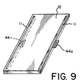
- the platen 12 may be constructed entirely of glass (not shown) or some other transparent material such that the lenticular material 14 can be fully supported and the beam 38 can pass through the transparent material and impinge upon detectors 44 and 44a.
- the platen 12 may be constructed of a material other than glass but includes narrow transparent inserts 11 along the full length of the lenticular material 14.
- the transparent inserts 11 need only be sufficiently wide so that the beam can pass through to the detectors 44 and 44a.
- the transparent inserts 11, if used, must be positioned so that the fixed detectors 44 and 44a will receive the deflected beam 38.
Landscapes
- Physics & Mathematics (AREA)
- General Physics & Mathematics (AREA)
- Optics & Photonics (AREA)
- Stereoscopic And Panoramic Photography (AREA)
- Laser Beam Printer (AREA)
- Length Measuring Devices By Optical Means (AREA)
- Mechanical Optical Scanning Systems (AREA)
Applications Claiming Priority (2)
| Application Number | Priority Date | Filing Date | Title |
|---|---|---|---|
| US217030 | 1998-12-21 | ||
| US09/217,030 US6087054A (en) | 1998-12-21 | 1998-12-21 | Detection and correction of skew between a reference and lenticules in lenticular material |
Publications (2)
| Publication Number | Publication Date |
|---|---|
| EP1014144A1 true EP1014144A1 (de) | 2000-06-28 |
| EP1014144B1 EP1014144B1 (de) | 2003-09-17 |
Family
ID=22809399
Family Applications (1)
| Application Number | Title | Priority Date | Filing Date |
|---|---|---|---|
| EP99203952A Expired - Lifetime EP1014144B1 (de) | 1998-12-21 | 1999-11-24 | Neigungskorrektur zwischen einem Linsenraster und einem Referenzstrahl |
Country Status (4)
| Country | Link |
|---|---|
| US (1) | US6087054A (de) |
| EP (1) | EP1014144B1 (de) |
| JP (1) | JP2000227639A (de) |
| DE (1) | DE69911363D1 (de) |
Cited By (4)
| Publication number | Priority date | Publication date | Assignee | Title |
|---|---|---|---|---|
| EP1065561A1 (de) * | 1999-06-29 | 2001-01-03 | Eastman Kodak Company | Schrägheitsprüfung und -Verbesserung zwischen einem Laserbündel und einem Linsenblatt |
| GB2352514A (en) * | 1999-07-23 | 2001-01-31 | Eastman Kodak Co | Rotational alignment of lenticular array |
| AT508826B1 (de) * | 2009-09-08 | 2012-02-15 | Context Type & Sign Pink Gmbh | Druckvorrichtung zur bedruckung einer linsenrasterfolie nach dem digitaldruckverfahren |
| CN103448378A (zh) * | 2012-05-28 | 2013-12-18 | 日本电产科宝株式会社 | 激光刻印机 |
Families Citing this family (6)
| Publication number | Priority date | Publication date | Assignee | Title |
|---|---|---|---|---|
| US6486937B2 (en) * | 1999-12-30 | 2002-11-26 | Eastman Kodak Company | Method and apparatus for printing large format lenticular images |
| US6615150B1 (en) | 2001-02-15 | 2003-09-02 | Eastman Kodak Company | Method for detecting errors in loading a lenticular material on a printer |
| JP5130863B2 (ja) * | 2007-10-18 | 2013-01-30 | セイコーエプソン株式会社 | 画像検査装置、画像検査方法および検査用画像作成方法 |
| US8136938B2 (en) * | 2009-05-19 | 2012-03-20 | William Karszes | System and method for printing on lenticular sheets |
| JP5296244B1 (ja) * | 2012-05-28 | 2013-09-25 | 日本電産コパル株式会社 | レーザマーカ |
| CN103786428B (zh) * | 2012-10-29 | 2017-03-01 | 小森公司 | 柱状透镜片的印刷机及印刷方法 |
Citations (7)
| Publication number | Priority date | Publication date | Assignee | Title |
|---|---|---|---|---|
| US4264809A (en) * | 1979-05-02 | 1981-04-28 | Eastman Kodak Company | Servo control loop using optical feedback |
| US5493326A (en) * | 1994-01-03 | 1996-02-20 | Xerox Corporation | Method and apparatus for scan line skew correction using a gradient index electrooptic prism |
| US5576852A (en) * | 1994-01-14 | 1996-11-19 | Konica Corporation | Synchronization signal generating unit of an image forming apparatus |
| EP0797343A2 (de) * | 1996-03-21 | 1997-09-24 | Kabushiki Kaisha Toshiba | Abtaststrahlpositionssteuerungsgerät zur Abtaststrahlpositionssteuerung und Bilderzeugungsgerät zu deren Verwendung |
| EP0801324A1 (de) * | 1996-04-10 | 1997-10-15 | Eastman Kodak Company | Vorrichtung und Verfahren zur Bildung eines zusammengesetzten Bildes |
| US5681676A (en) * | 1992-05-11 | 1997-10-28 | Polaroid Corporation | Registration method |
| US5697006A (en) * | 1992-02-06 | 1997-12-09 | Fuji Photo Film Co., Ltd. | Method and apparatus for recording stereoscopic images and lenticular recording material used therefor |
Family Cites Families (3)
| Publication number | Priority date | Publication date | Assignee | Title |
|---|---|---|---|---|
| US3534164A (en) * | 1967-04-18 | 1970-10-13 | Gen Electric | Method and apparatus for producing 3d pictures utilizing a scanning electron beam |
| JP3471930B2 (ja) * | 1994-11-10 | 2003-12-02 | キヤノン株式会社 | インクジェット記録装置 |
| US5689340A (en) * | 1995-12-06 | 1997-11-18 | Eastman Kodak Company | Apparatus and method for measuring alignment in lenticular media |
-
1998
- 1998-12-21 US US09/217,030 patent/US6087054A/en not_active Expired - Lifetime
-
1999
- 1999-11-24 EP EP99203952A patent/EP1014144B1/de not_active Expired - Lifetime
- 1999-11-24 DE DE69911363T patent/DE69911363D1/de not_active Expired - Lifetime
- 1999-12-17 JP JP11359944A patent/JP2000227639A/ja active Pending
Patent Citations (7)
| Publication number | Priority date | Publication date | Assignee | Title |
|---|---|---|---|---|
| US4264809A (en) * | 1979-05-02 | 1981-04-28 | Eastman Kodak Company | Servo control loop using optical feedback |
| US5697006A (en) * | 1992-02-06 | 1997-12-09 | Fuji Photo Film Co., Ltd. | Method and apparatus for recording stereoscopic images and lenticular recording material used therefor |
| US5681676A (en) * | 1992-05-11 | 1997-10-28 | Polaroid Corporation | Registration method |
| US5493326A (en) * | 1994-01-03 | 1996-02-20 | Xerox Corporation | Method and apparatus for scan line skew correction using a gradient index electrooptic prism |
| US5576852A (en) * | 1994-01-14 | 1996-11-19 | Konica Corporation | Synchronization signal generating unit of an image forming apparatus |
| EP0797343A2 (de) * | 1996-03-21 | 1997-09-24 | Kabushiki Kaisha Toshiba | Abtaststrahlpositionssteuerungsgerät zur Abtaststrahlpositionssteuerung und Bilderzeugungsgerät zu deren Verwendung |
| EP0801324A1 (de) * | 1996-04-10 | 1997-10-15 | Eastman Kodak Company | Vorrichtung und Verfahren zur Bildung eines zusammengesetzten Bildes |
Cited By (6)
| Publication number | Priority date | Publication date | Assignee | Title |
|---|---|---|---|---|
| EP1065561A1 (de) * | 1999-06-29 | 2001-01-03 | Eastman Kodak Company | Schrägheitsprüfung und -Verbesserung zwischen einem Laserbündel und einem Linsenblatt |
| GB2352514A (en) * | 1999-07-23 | 2001-01-31 | Eastman Kodak Co | Rotational alignment of lenticular array |
| GB2352514B (en) * | 1999-07-23 | 2003-12-17 | Eastman Kodak Co | An improved method and apparatus for precise positioning of arrays with periodic structures relative to composite images |
| AT508826B1 (de) * | 2009-09-08 | 2012-02-15 | Context Type & Sign Pink Gmbh | Druckvorrichtung zur bedruckung einer linsenrasterfolie nach dem digitaldruckverfahren |
| CN103448378A (zh) * | 2012-05-28 | 2013-12-18 | 日本电产科宝株式会社 | 激光刻印机 |
| CN103448378B (zh) * | 2012-05-28 | 2015-10-28 | 日本电产科宝株式会社 | 激光刻印机 |
Also Published As
| Publication number | Publication date |
|---|---|
| US6087054A (en) | 2000-07-11 |
| DE69911363D1 (de) | 2003-10-23 |
| JP2000227639A (ja) | 2000-08-15 |
| EP1014144B1 (de) | 2003-09-17 |
Similar Documents
| Publication | Publication Date | Title |
|---|---|---|
| CA2077832C (en) | Method and apparatus for image registration in a single pass ros system | |
| EP0729265B1 (de) | Abtastgerät | |
| US6177217B1 (en) | Method and apparatus for precise positioning of arrays with periodic structures | |
| EP1014144B1 (de) | Neigungskorrektur zwischen einem Linsenraster und einem Referenzstrahl | |
| US6154247A (en) | Skew correction in lenticular material printing | |
| US5889545A (en) | Method and apparatus for image registration in a single pass ROS printer using a rotatable output window with no optical power | |
| US5493326A (en) | Method and apparatus for scan line skew correction using a gradient index electrooptic prism | |
| US6249384B1 (en) | Detection and correction of skew between a writing laser beam and lenticules in lenticular material | |
| EP0816943B1 (de) | Bildausrichtungssystem und -verfahren | |
| EP0589654B1 (de) | Vorrichtung und Gerät zur Positionsteuerung von Abstastzeilen in der Unterabtastrichtung in einem Mehrfarbenelektrostatographischen Gerät | |
| EP1059551A2 (de) | Vorrichtung zur Schräglagenkorrektur von Abtastzeilen in einem optischen Abtaster | |
| US4587420A (en) | Light beam scanning device for correcting scanning speed | |
| JP2000180748A (ja) | 分割走査装置及び分割走査装置のビーム状態調整方法 | |
| JP2001066549A (ja) | 合成像に対して周期構造を有するアレイを配置する方法及びその装置 | |
| JPS6115119A (ja) | レ−ザプリンタ | |
| US20010002147A1 (en) | Detection of pitch variations in lenticular material | |
| JP2001108930A (ja) | 走査光学装置及びその制御方法 | |
| US6727972B2 (en) | Detection of pitch variations in lenticular material | |
| JPH08132670A (ja) | 光ビ−ム同期検出装置及び画像形成装置 | |
| US6717649B2 (en) | Detection of pitch variations in lenticular material | |
| JP3141597B2 (ja) | 光学走査装置 | |
| JPS6115118A (ja) | レ−ザプリンタ | |
| JPH0519204A (ja) | 走査光学装置 | |
| JPS6115121A (ja) | レ−ザプリンタ | |
| JPH0453288B2 (de) |
Legal Events
| Date | Code | Title | Description |
|---|---|---|---|
| PUAI | Public reference made under article 153(3) epc to a published international application that has entered the european phase |
Free format text: ORIGINAL CODE: 0009012 |
|
| AK | Designated contracting states |
Kind code of ref document: A1 Designated state(s): DE FR GB |
|
| AX | Request for extension of the european patent |
Free format text: AL;LT;LV;MK;RO;SI |
|
| 17P | Request for examination filed |
Effective date: 20001201 |
|
| AKX | Designation fees paid |
Free format text: DE FR GB |
|
| 17Q | First examination report despatched |
Effective date: 20020801 |
|
| GRAH | Despatch of communication of intention to grant a patent |
Free format text: ORIGINAL CODE: EPIDOS IGRA |
|
| GRAS | Grant fee paid |
Free format text: ORIGINAL CODE: EPIDOSNIGR3 |
|
| GRAA | (expected) grant |
Free format text: ORIGINAL CODE: 0009210 |
|
| AK | Designated contracting states |
Kind code of ref document: B1 Designated state(s): DE FR GB |
|
| PG25 | Lapsed in a contracting state [announced via postgrant information from national office to epo] |
Ref country code: FR Free format text: LAPSE BECAUSE OF FAILURE TO SUBMIT A TRANSLATION OF THE DESCRIPTION OR TO PAY THE FEE WITHIN THE PRESCRIBED TIME-LIMIT Effective date: 20030917 |
|
| REG | Reference to a national code |
Ref country code: GB Ref legal event code: FG4D |
|
| REF | Corresponds to: |
Ref document number: 69911363 Country of ref document: DE Date of ref document: 20031023 Kind code of ref document: P |
|
| PG25 | Lapsed in a contracting state [announced via postgrant information from national office to epo] |
Ref country code: GB Free format text: LAPSE BECAUSE OF NON-PAYMENT OF DUE FEES Effective date: 20031217 |
|
| PG25 | Lapsed in a contracting state [announced via postgrant information from national office to epo] |
Ref country code: DE Free format text: LAPSE BECAUSE OF FAILURE TO SUBMIT A TRANSLATION OF THE DESCRIPTION OR TO PAY THE FEE WITHIN THE PRESCRIBED TIME-LIMIT Effective date: 20031218 |
|
| PLBE | No opposition filed within time limit |
Free format text: ORIGINAL CODE: 0009261 |
|
| STAA | Information on the status of an ep patent application or granted ep patent |
Free format text: STATUS: NO OPPOSITION FILED WITHIN TIME LIMIT |
|
| GBPC | Gb: european patent ceased through non-payment of renewal fee |
Effective date: 20031217 |
|
| 26N | No opposition filed |
Effective date: 20040618 |
|
| EN | Fr: translation not filed |