EP1014165A2 - Photographische Filmeinheit und Einmalkamera - Google Patents
Photographische Filmeinheit und Einmalkamera Download PDFInfo
- Publication number
- EP1014165A2 EP1014165A2 EP99204115A EP99204115A EP1014165A2 EP 1014165 A2 EP1014165 A2 EP 1014165A2 EP 99204115 A EP99204115 A EP 99204115A EP 99204115 A EP99204115 A EP 99204115A EP 1014165 A2 EP1014165 A2 EP 1014165A2
- Authority
- EP
- European Patent Office
- Prior art keywords
- filmstrip
- leader
- film unit
- spool
- segment
- Prior art date
- Legal status (The legal status is an assumption and is not a legal conclusion. Google has not performed a legal analysis and makes no representation as to the accuracy of the status listed.)
- Withdrawn
Links
- 238000000926 separation method Methods 0.000 claims abstract description 27
- 230000007723 transport mechanism Effects 0.000 description 4
- 230000000295 complement effect Effects 0.000 description 2
- 238000004804 winding Methods 0.000 description 2
- 239000000853 adhesive Substances 0.000 description 1
- 230000001070 adhesive effect Effects 0.000 description 1
- 230000000712 assembly Effects 0.000 description 1
- 238000000429 assembly Methods 0.000 description 1
- 238000005266 casting Methods 0.000 description 1
- 230000000694 effects Effects 0.000 description 1
- 239000000463 material Substances 0.000 description 1
- 238000000034 method Methods 0.000 description 1
- 230000032258 transport Effects 0.000 description 1
Images


Classifications
-
- G—PHYSICS
- G03—PHOTOGRAPHY; CINEMATOGRAPHY; ANALOGOUS TECHNIQUES USING WAVES OTHER THAN OPTICAL WAVES; ELECTROGRAPHY; HOLOGRAPHY
- G03B—APPARATUS OR ARRANGEMENTS FOR TAKING PHOTOGRAPHS OR FOR PROJECTING OR VIEWING THEM; APPARATUS OR ARRANGEMENTS EMPLOYING ANALOGOUS TECHNIQUES USING WAVES OTHER THAN OPTICAL WAVES; ACCESSORIES THEREFOR
- G03B17/00—Details of cameras or camera bodies; Accessories therefor
- G03B17/28—Locating light-sensitive material within camera
- G03B17/30—Locating spools or other rotatable holders of coiled film
-
- G—PHYSICS
- G03—PHOTOGRAPHY; CINEMATOGRAPHY; ANALOGOUS TECHNIQUES USING WAVES OTHER THAN OPTICAL WAVES; ELECTROGRAPHY; HOLOGRAPHY
- G03B—APPARATUS OR ARRANGEMENTS FOR TAKING PHOTOGRAPHS OR FOR PROJECTING OR VIEWING THEM; APPARATUS OR ARRANGEMENTS EMPLOYING ANALOGOUS TECHNIQUES USING WAVES OTHER THAN OPTICAL WAVES; ACCESSORIES THEREFOR
- G03B19/00—Cameras
- G03B19/02—Still-picture cameras
- G03B19/04—Roll-film cameras
Definitions
- the invention relates to photography and more particularly relates to a photographic film unit and one-time use camera.
- Photographic film units are subject to a number of competing considerations.
- a bare filmstrip is difficult to handle and is not light-tight by itself.
- Type 120 film adds a spool and opaque backing paper.
- Another roll film, Type 220 has a spool, an opaque paper leader, and an opaque paper trailer attached to the filmstrip.
- Cartridge films such as Type 135, Type 126, Type 110, and Advanced Photo SystemTM add a one or two chamber shell over a spool.
- One-time use cameras add camera features to a simpler filmstrip or film unit and are subject to similar trade-offs.
- a one-time use camera that includes a film cartridge requires less care in exposed film removal than a one-time use camera that uses roll film, but is larger and more complex.
- a photographic film unit has a spool having a shaft and a pair of opposed flanges fixed to the shaft.
- the shaft defines a spool axis.
- the flanges each have an inner face and an outer face.
- the inner faces each have a main portion and a periphery.
- the periphery is disposed radially and axially outward from the main portion.
- the filmstrip has opposed first and second ends. The first end is wound on the shaft.
- the filmstrip has a transverse dimension less than the axial separation of the main portions.
- a leader is conjoined with the second end.
- the leader has an inner segment adjoining the filmstrip and an outer segment adjoining the inner segment.
- the inner segment has a transverse dimension less than the axial separation of the main portions.
- the outer segment has a transverse dimension less than the axial separation of the peripheries.
- an improved film unit is provided that is compact and relatively simple, but combines good light-tightness with ease of use.
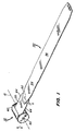
- the photographic film unit 10 has a spool 30 onto which a filmstrip 20 is wound.
- the spool 30 has a longitudinal axis 12 about which the spool 30 can be rotated to wind or unwind the filmstrip 20.
- the spool 30 has a shaft 14 and a pair of opposed flanges 16,18 extending out from the shaft 14.
- the spool 30 can be an assembly of multiple pieces, but it is preferred that the spool 30 be a one-piece plastic casting.
- the overall dimensions of the spool 30 are adapted to meet the requirements of a particular type of filmstrip 20.
- the figures illustrate a film unit 10 having a filmstrip 20 about like the filmstrip used in Advanced Photo SystemTM(APSTM) film. Relative proportions of the spool 30 would differ if the filmstrip 20 used was like those in Type 135, Type 110, or Type 120 film.
- FIG. 1 and 2 An exposure portion of the filmstrip 20 is shown in Figures 1 and 2 wound onto the spool 30 over a first end 22 of the filmstrip 20.
- a second end 24 of the filmstrip 20 extends outward and is conjoined with a leader 50 by a patch 52 of adhesive or other bonding or tape or the like.
- the leader 50 has an inner segment 54 adjoining the filmstrip 20 and an outer segment 56 adjoining, and extending outward from the inner segment 54.
- the leader 50 is preferably opaque.
- the filmstrip 20 has a stiffness as in the other film types mentioned above.
- the leader 50 is less stiff than the filmstrip 20 and can be paper or plastic, like the paper leader used in Type 120 film.
- the shaft 14 of the spool 30 is shaped so as to receive and hold the first end 22 of the filmstrip 20.
- the shaft 14 can be cylindrical and the first end 22 of the filmstrip 20 can be attached by a patch 52 or tape or the like.
- the shaft 14 can have a slot or other structure (not illustrated) shaped complementary to an attachment feature (not shown) of the first end 22 of the filmstrip 20. Suitable structures and attachment features, such as those used for Type 120 film, are well known to those of skill in the art.
- the flanges 16,18 of the spool 30 each have an inner face 36 and an outer face 38.
- the outer faces 38 are configured so as to interface with the film transport mechanism of a suitable camera 70 or other piece of photographic equipment (illustrated in Figure 1, by a spindle 40).
- the outer faces 38 each have a central pocket 32 that is shaped to receive a part of the transport mechanism.
- the upper flange 16 has a boss 34 surrounding the pocket 32.
- One or more of these features can be faceted (not separately illustrated) to engage and rotate with a complementary spindle or other part of the transport mechanism.
- a faceted spindle is shown in Figure 1 in engagement with the faceted pocket 32 of upper flange 16.
- the spool 30 is radially symmetrical about the longitudinal axis 12.
- the inner faces 36 each have a main portion 42, a periphery 44 disposed radially and axially outward from the main portion 42, and a step 46 between the main portion 42 and periphery 44.
- the main portions 42 are each shaped like a circular track or band.
- the steps 46 each extend radially and axially outward from a respective main portion 42.
- the main portions 42 of the inner faces 36 each extend radial to the spool 30 axis 12 such that the main portions 42 have a uniform separation, indicated in Figures 2 and 3 as a main portion 42 separation dimension "A".
- axial dimensions of the filmstrip 20 are referred to by letter and the term "separation dimension”.
- Dimensions of the filmstrip 20 are referred to by letter and the term "transverse dimension”. It is assumed for purposes of explanation that the longitudinal edges 64 of the filmstrip 20 and longitudinal margins 66 of the leader 50 are perpendicular to the spool axis 12. This is ordinarily the case unless the film is twisted.)
- the exposure portion of the filmstrip 20 has a uniform separation between the longitudinal edges 64 of the filmstrip 20.
- This transverse dimension of the filmstrip 20 is indicated by the letter “B” in Figures 2-3. Dimension “B” is smaller than, but close to the size of dimension "A”. (With the filmstrip 20 wound on the spool 30 "B” is also parallel to "A”.) As is the case with other film types, the transverse dimension "B” would be standardized within close tolerances to permit ready usage of the filmstrip 20 in automated processing equipment and the like.
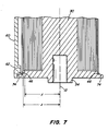
- the radial dimension of the main portions 42 is at least as large as the radial dimension of the coiled filmstrip 20, indicated by “Y” in Figure 7, so that axial movement of the coiled filmstrip 20 is blocked and none of the coiled filmstrip 20 can telescope over a distance of greater than the difference between "A" and "B".
- the peripheries 44 of the inner faces 36 have a separation, indicated in Figure 3 as a periphery 44 separation dimension "C".
- the outer segment 56 of the leader 50 has a pair of longitudinal margins 66 that have a separation, shown in Figure 2 as transverse dimension "D", that is greater than dimensions "A" and "B", but less than dimension "C”.
- the outer segment 56 of the leader 50 is wider than the exposure portion 48 of the filmstrip 20 and also wider than the axial separation of the main portions 42 of the inner faces 36 of the flanges 16,18, but narrower than the axial separation of the peripheries 44 of the inner faces 36.
- the inner segment 54 of the leader 50 has a pair of longitudinal margins 67 that have a maximum separation, shown in Figure 2 as transverse dimension "E", that is less than dimension "A".
- the inner segment 54 of the leader 50 is narrower than the axial separation of the main portions 42 of the inner faces 36 of the flanges 16,18.
- the inner segment 54 of the leader 50 can be wound onto the spool 30 right over the filmstrip 20 without wrinkling or other distortion.
- the radial dimension of the main portions 42 is at least as large as the radial dimension of the combination of the coiled filmstrip 20 and inner segment 54, this is shown as radial dimension "Z" in Figure 7.
- the outer segment 56 is wound over the inner segment 54.
- the width of the outer segment 56 transverse dimension "D" causes the outer segment 56 to also wind onto the step 46.
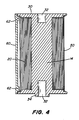
- the steps 46 extend radially and axially outward from the respective main portions 42 and, preferably, have an L-shaped partial cross-section, with a curb portion 72 that faces circumferentially outward and a flange portion 74 that is transverse to the spool axis 12.
- the curb portion 72 of the step 46 is radially aligned with the coiled filmstrip 20 and inner segment 54. That is, the radial dimension of the main portions 42 is the same as the radial dimension of the combination of the coiled filmstrip 20 and the inner segment 54.
- the flange portions 74 of the steps 46 are separated by a minimum or uniform separation dimension "F", shown in Figures 2 and 3. It is further preferred that the transverse dimension "D" of the outer segment 56 is greater than the separation dimension "F". In this case, the outer segment 56 is wider than the available space and must curl against one or both flange portions 74 when the outer segment 56 is wound onto the spool 30 over the inner segment 54 and filmstrip 20.
- the flange portions 74 are substantially radial to the spool axis 12, that is, radial or angled outward less than about 20 degrees, to help ensure a tight fit between the outer segment 56 and the flange portion 74.
- the outer segment 56 can be wound so as to provide an even overlap of the step 46 on each flange portion 74, as shown in Figure 4, however, since the outer segment 56 provide a light-tight fit even if only one longitudinal margin overlaps a flange portion 74 while the other longitudinal portion abuts the other flange portion 74, as shown in Figure 5.
- the film unit 10 can be configured to help ensure that the outer segment 56 consistently winds so as to evenly overlap both flange portions 74, as shown in Figure 4.
- the inner segment 54 tapers longitudinally outward from a narrowed tongue 58 that is joined to the filmstrip 20.
- the tongue 58 and second end 24 of the filmstrip 20 are joined together only in a central region spaced apart from the longitudinal edges 64 of the filmstrip 20 and the longitudinal margins 66,67 of the leader 50.
- the area of attachment of the filmstrip 20 and tongue 58 is also preferably inset from the transverse edges 68 of the filmstrip 20 and leader 50 to help allow the leader 50 to pivot slightly relative to the filmstrip 20 during winding. This slight pivoting is sufficient in many cases to provide the even overlap of Figure 4.
- the film unit 10 has a retainer clip 60 that is joined to the flanges 16,18 exterior to the steps 46.
- the retainer clip 60 provides some protection for the filmstrip 20 and leader 50 and, more importantly, holds the outer segment 56 of the leader 50 in place on the spool 30. (The filmstrip 20 and leader 50 tend to clockspring radially outward. This resilience holds the leader 50 in place against the retainer clip 60.)
- the retainer clip 60 is C-shaped in radial cross-section and extends around about 270 degrees of circumference of the flanges 16,18. The retainer clip 60 is not light-tight over the filmstrip 20 and can be opaque or transparent, as desired.
- the retainer clip 60 can be permanently fixed to the flanges 16,18, but this is unnecessary and may make film processing more cumbersome.
- the retainer clip 60 can instead be held in place on the flanges 16,18 by resilience of the plastic or other material of the retainer clip 60.
- the retainer clip 60 can be sized to freely rotate about the flanges 16,18 during use. This allows the filmstrip 20 to slightly realign the retainer clip 60, if necessary, during film winding in a camera 70.
- the retainer clip 60 has a pair of internal ribs 62.
- the ribs 62 are positioned to overlap the longitudinal edges 64 of the filmstrip 20 and longitudinal margins 66,67 of the leader 50.
- the separation of the ribs 62 and the leader 50 can be adjusted so as to holder the leader 50 in place when the leader 50 is fully wound onto the spool 30 while at the same time allowing the leader 50 to be withdrawn from the spool 30 with a limited amount of effort.
- a one-time use camera 70 including the film unit 10 is shown in Figure 6.
- the camera 70 has a body 81 including a shell 82 and a frame 84 having first and second film chambers 76,78.
- An capture system is disposed in the body 81.
- the capture system is illustrated as a viewfinder 80a and an exposure frame 80b disposed between the film chambers 76,78.
- Features of capture systems, such as film transports, shutter systems, flash assemblies, and the like are well known in the art.
- the spool 30 of the film unit 10 is disposed in one of the film chambers 76.
- the first end 22 of the filmstrip 20 is attached to the spool 30. Prior to exposure of the film, the leader 50 and exposure portion of the film is disposed in the other chamber 78.
- the filmstrip 20 is wound onto the spool 30.
- the leader 50 is wound onto the spool 30 over the filmstrip 20 in a similar manner to that in cameras that use Type 120 film.
- the filmstrip 20 can be wound on a secondary spool 30 or the filmstrip 20 can be coiled around a hollow core (not illustrated).
- the filmstrip 20 can be loaded into the camera body 81 by any of a variety of methods of loading one-time use cameras and two-chamber film cartridges well known to those of skill in the art.
Landscapes
- Physics & Mathematics (AREA)
- General Physics & Mathematics (AREA)
- Details Of Cameras Including Film Mechanisms (AREA)
- Storing, Repeated Paying-Out, And Re-Storing Of Elongated Articles (AREA)
Applications Claiming Priority (2)
| Application Number | Priority Date | Filing Date | Title |
|---|---|---|---|
| US09/218,870 US6190061B1 (en) | 1998-12-22 | 1998-12-22 | Photographic film unit and one-time use camera |
| US218870 | 1998-12-22 |
Publications (2)
| Publication Number | Publication Date |
|---|---|
| EP1014165A2 true EP1014165A2 (de) | 2000-06-28 |
| EP1014165A3 EP1014165A3 (de) | 2003-12-17 |
Family
ID=22816820
Family Applications (1)
| Application Number | Title | Priority Date | Filing Date |
|---|---|---|---|
| EP99204115A Withdrawn EP1014165A3 (de) | 1998-12-22 | 1999-12-03 | Photographische Filmeinheit und Einmalkamera |
Country Status (3)
| Country | Link |
|---|---|
| US (1) | US6190061B1 (de) |
| EP (1) | EP1014165A3 (de) |
| JP (1) | JP2000187308A (de) |
Families Citing this family (4)
| Publication number | Priority date | Publication date | Assignee | Title |
|---|---|---|---|---|
| US6526228B2 (en) | 2001-04-26 | 2003-02-25 | Eastman Kodak Company | One-time use camera assembly process having filmstrip anchored during camera frame assembly transport |
| US6526229B2 (en) | 2001-04-26 | 2003-02-25 | Eastman Kodak Company | Camera having a filmstrip holdfast spaced apart from a film path and transportable camera intermediate |
| US7215880B2 (en) * | 2004-11-01 | 2007-05-08 | Eastman Kodak Company | One-time-use camera |
| CN111776810B (zh) * | 2020-07-20 | 2022-02-08 | 山东工程职业技术大学 | 一种建筑设计用方便查看图纸的卷收装置 |
Family Cites Families (11)
| Publication number | Priority date | Publication date | Assignee | Title |
|---|---|---|---|---|
| US2176507A (en) * | 1936-10-26 | 1939-10-17 | Eastman Kodak Co | Roll film for a cassette |
| US2541476A (en) * | 1949-10-12 | 1951-02-13 | Eastman Kodak Co | Light-tight film cartridge |
| US3232024A (en) * | 1962-05-14 | 1966-02-01 | United Shoe Machinery Corp | Package preforming apparatus |
| DE2632766A1 (de) * | 1976-07-21 | 1978-01-26 | Agfa Gevaert Ag | Flachbandspule mit bandbefestigung am kern |
| US4295713A (en) | 1979-03-14 | 1981-10-20 | Eastman Kodak Company | Film and photographic apparatus |
| US4423943A (en) * | 1982-04-02 | 1984-01-03 | Polaroid Corporation | Photographic film assemblage having a non-lighttight film withdrawal opening |
| US5492221A (en) * | 1994-11-02 | 1996-02-20 | Eastman Kodak Company | Light-tight package |
| US5608482A (en) * | 1996-04-24 | 1997-03-04 | Eastman Kodak Company | Film loading method and related apparatus |
| US5918083A (en) * | 1997-02-19 | 1999-06-29 | Fuji Photo Optical Co., Ltd. | Camera for use with a roll photo film |
| US5797045A (en) * | 1997-05-30 | 1998-08-18 | Eastman Kodak Company | Three roller film winder and method |
| US5790912A (en) * | 1997-06-13 | 1998-08-04 | Eastman Kodak Company | Light sensitive leader closure for roll film |
-
1998
- 1998-12-22 US US09/218,870 patent/US6190061B1/en not_active Expired - Fee Related
-
1999
- 1999-12-03 EP EP99204115A patent/EP1014165A3/de not_active Withdrawn
- 1999-12-08 JP JP11348284A patent/JP2000187308A/ja active Pending
Also Published As
| Publication number | Publication date |
|---|---|
| EP1014165A3 (de) | 2003-12-17 |
| US6190061B1 (en) | 2001-02-20 |
| JP2000187308A (ja) | 2000-07-04 |
Similar Documents
| Publication | Publication Date | Title |
|---|---|---|
| US4887110A (en) | Film cassette | |
| US4834306A (en) | Film cassette | |
| EP0427922B1 (de) | Kameravorrichtung zur Ladeblockierung eines belichteten Films | |
| EP0436774B1 (de) | Filmkassette | |
| US4832275A (en) | Film cassette | |
| US4875638A (en) | Film cassette | |
| EP0413968B1 (de) | Filmkassette mit einem Zeiger des Filmbelichtungszustands | |
| EP0386625A1 (de) | Filmkassette | |
| EP0421097B1 (de) | Filmkassette | |
| US4894673A (en) | Film cassette | |
| US5040739A (en) | Film-thrusting cassette | |
| US5004176A (en) | Film cassette | |
| CA2046136C (en) | Film cassette with exposure status indicator | |
| US6190061B1 (en) | Photographic film unit and one-time use camera | |
| CA2052415A1 (en) | Camera apparatus for use with film cassette having locking means for exposure status indicator | |
| US4875637A (en) | Film cassette | |
| US5031855A (en) | Film-thrusting cassette | |
| US5046679A (en) | Film thrusting cassette | |
| US5046681A (en) | Film cassette | |
| US5153627A (en) | Film cassette with spool lock | |
| US5046682A (en) | Film cassette | |
| US4956658A (en) | Film threading apparatus | |
| CA2031107C (en) | Film cassette | |
| US5229804A (en) | Film assemblage | |
| EP0554921A2 (de) | Filmkassette |
Legal Events
| Date | Code | Title | Description |
|---|---|---|---|
| PUAI | Public reference made under article 153(3) epc to a published international application that has entered the european phase |
Free format text: ORIGINAL CODE: 0009012 |
|
| AK | Designated contracting states |
Kind code of ref document: A2 Designated state(s): AT BE CH CY DE DK ES FI FR GB GR IE IT LI LU MC NL PT SE |
|
| AX | Request for extension of the european patent |
Free format text: AL;LT;LV;MK;RO;SI |
|
| PUAL | Search report despatched |
Free format text: ORIGINAL CODE: 0009013 |
|
| AK | Designated contracting states |
Kind code of ref document: A3 Designated state(s): AT BE CH CY DE DK ES FI FR GB GR IE IT LI LU MC NL PT SE |
|
| AX | Request for extension of the european patent |
Extension state: AL LT LV MK RO SI |
|
| RIC1 | Information provided on ipc code assigned before grant |
Ipc: 7G 03B 19/04 B Ipc: 7G 03C 3/02 B Ipc: 7G 03B 17/26 A |
|
| AKX | Designation fees paid | ||
| REG | Reference to a national code |
Ref country code: DE Ref legal event code: 8566 |
|
| STAA | Information on the status of an ep patent application or granted ep patent |
Free format text: STATUS: THE APPLICATION IS DEEMED TO BE WITHDRAWN |
|
| 18D | Application deemed to be withdrawn |
Effective date: 20040618 |