EP1014227B1 - Zeitmessvorrichtung und verfahren zu ihrer kontrolle - Google Patents
Zeitmessvorrichtung und verfahren zu ihrer kontrolle Download PDFInfo
- Publication number
- EP1014227B1 EP1014227B1 EP99309937A EP99309937A EP1014227B1 EP 1014227 B1 EP1014227 B1 EP 1014227B1 EP 99309937 A EP99309937 A EP 99309937A EP 99309937 A EP99309937 A EP 99309937A EP 1014227 B1 EP1014227 B1 EP 1014227B1
- Authority
- EP
- European Patent Office
- Prior art keywords
- time
- indication
- hand
- driving
- hand driving
- Prior art date
- Legal status (The legal status is an assumption and is not a legal conclusion. Google has not performed a legal analysis and makes no representation as to the accuracy of the status listed.)
- Expired - Lifetime
Links
- 238000005259 measurement Methods 0.000 title claims description 74
- 238000000034 method Methods 0.000 title claims description 48
- 238000001514 detection method Methods 0.000 claims description 48
- 238000010248 power generation Methods 0.000 claims description 22
- 210000004247 hand Anatomy 0.000 description 88
- 230000008569 process Effects 0.000 description 32
- 230000004048 modification Effects 0.000 description 29
- 238000012986 modification Methods 0.000 description 29
- 239000003990 capacitor Substances 0.000 description 22
- 230000004044 response Effects 0.000 description 22
- 230000007246 mechanism Effects 0.000 description 13
- 230000033001 locomotion Effects 0.000 description 9
- 238000010276 construction Methods 0.000 description 7
- 238000010586 diagram Methods 0.000 description 6
- 230000005540 biological transmission Effects 0.000 description 3
- 230000007423 decrease Effects 0.000 description 3
- 230000005674 electromagnetic induction Effects 0.000 description 3
- 230000010355 oscillation Effects 0.000 description 3
- 238000005265 energy consumption Methods 0.000 description 2
- 230000009467 reduction Effects 0.000 description 2
- 230000000630 rising effect Effects 0.000 description 2
- 230000001960 triggered effect Effects 0.000 description 2
- 230000001133 acceleration Effects 0.000 description 1
- 230000008859 change Effects 0.000 description 1
- 238000004891 communication Methods 0.000 description 1
- 230000000052 comparative effect Effects 0.000 description 1
- 230000003203 everyday effect Effects 0.000 description 1
- 230000005284 excitation Effects 0.000 description 1
- 238000007667 floating Methods 0.000 description 1
- 230000006870 function Effects 0.000 description 1
- 230000002093 peripheral effect Effects 0.000 description 1
- 239000010453 quartz Substances 0.000 description 1
- 238000005070 sampling Methods 0.000 description 1
- VYPSYNLAJGMNEJ-UHFFFAOYSA-N silicon dioxide Inorganic materials O=[Si]=O VYPSYNLAJGMNEJ-UHFFFAOYSA-N 0.000 description 1
- 230000001052 transient effect Effects 0.000 description 1
- 230000007704 transition Effects 0.000 description 1
- 210000000707 wrist Anatomy 0.000 description 1
Images


Classifications
-
- G—PHYSICS
- G04—HOROLOGY
- G04C—ELECTROMECHANICAL CLOCKS OR WATCHES
- G04C9/00—Electrically-actuated devices for setting the time-indicating means
-
- G—PHYSICS
- G04—HOROLOGY
- G04G—ELECTRONIC TIME-PIECES
- G04G19/00—Electric power supply circuits specially adapted for use in electronic time-pieces
Definitions
- the present invention relates to a time-measurement device having the capability of indicating time and also to a method of controlling such a time-measurement device.
- the present invention relates to a time-measurement device and a method of controlling the same. More specifically, the present invention relates to a time-measurement device having the capability of automatically switching the operating mode from a power saving mode to a normal mode and also to a method of controlling such a time-measurement device.
- a time-measurement device which includes an electric power generator, a power supply, and an electric power consuming part wherein electric power generated by the electric power generator is stored in the power supply and the electric power stored in the power supply is consumed by the electric power consuming part.
- Some time-measurement devices of this type have, in addition to a normal driving mode in which electric power is consumed, a power saving mode in which the electric power consumed by the electric power consuming part is saved, wherein the operating mode is switched to the power saving mode depending on the condition in which a user uses the time-measurement device.
- a specific example of the application of the mode switching capability described above is a wristwatch which operates in a normal time indication mode (normal mode, normal driving mode) when the wristwatch is being carried by a user and also during a predetermined period of time after the end of the carrying state. If the predetermined period of time has elapsed after the end of the carrying state, the operating mode automatically switches to the power saving mode in which indication functions are partially stopped so as to save the stored electric power.
- This wristwatch returns to the normal time indication mode (normal mode) in which the current time is indicated by hands from the power saving mode in which the driving of the hands is stopped, in a manner as described below.
- a single motor is generally rotated at a higher speed than a normal speed at which the hands are driven in the normal mode so that all hands are driven quickly to adjust the indication of time to the current time.
- the hour, minute, and second hands are driven quickly by amounts by which the hands would have been driven during the period of time elapsed in the power saving mode if the operating mode were in the normal time indication mode.
- a technique of solving the above problems is to drive the hands using a plurality of motors.
- the power consumption increases.
- the increase in the power consumption can cause the power supply voltage to become unstable and thus can cause the adjusting of the indication of time to fail.
- the hands are moved by small amounts in the operation of adjusting the indication of time, it is difficult for a user to visually recognize whether or not the indication of time has been correctly adjusted.
- US 4744067 discloses an analog electric watch having a power saving mode in which a second hand movement is stopped when a power supply is insufficient. When the power supply is restored, the correct portion of the second hand is recovered by a custom circuit including a stepper motor.
- a time-measurement device comprising: power supply means for supplying electric power; time indicating means including a plurality of indication hand driving parts for driving corresponding indication hands using electric power supplied by the power supply means so as to indicate time by the plurality of indication hands; control means for switching the operating mode for each of the indication hand driving parts in accordance with a predetermined condition, between a power saving mode in which the corresponding indication hand is not driven and a normal indication mode in which the corresponding indication hand is continuously driven; elapsed-time storage means for storing the time elapsed in the power saving mode; and time adjusting means for adjusting indication of time by driving the indication hands using the indication hand driving parts in accordance with the time elapsed in the power saving mode when the operating mode is switched from the power saving mode to the normal indication mode; wherein the time adjusting means includes time adjusting operation control means for controlling the timing of driving the indication hand driving parts in the operation of adjusting the indication of time such that the plurality of indication hand driving parts
- time adjusting operation control means sets the adjusting operation periods for the plurality of indication hand driving parts such that there is no overlap among the operation periods.
- a time-measurement device wherein the time adjusting means adjusts the indication of time such that, of said plurality of indication hand driving parts, an indication hand driving part having a lower normal driving speed is driven for adjustment before an indication hand driving part having a higher normal driving speed is driven for adjustment.
- a time-measurement device wherein the time adjusting means adjusts the indication of time such that, of said plurality of indication hand driving parts, an indication hand driving part having a higher normal driving speed is driven for adjustment before an indication hand driving part having a lower normal driving speed is driven for adjustment.
- a time-measurement device wherein the time adjusting means adjusts the indication of time such that a hour/minute hand driving means is driven preceding a second hand driving means, and the second hand driving means is driven after completion of driving of the hour and minute hands.
- a time-measurement device wherein when the time adjusting means adjusts the indication of time, the time adjusting means drives the plurality of hand driving parts by outputting driving pulses to the plurality of hand driving parts such that there is no overlapping in the timing of outputting the driving pulses.
- a time-measurement device wherein when the time adjusting means adjusts the indication of time, the time adjusting means drives an hour hand driving means, a minute hand driving means, and a second hand driving means in an exclusive fashion in the following order: hour hand driving means ⁇ minute hand driving means ⁇ second hand driving means.
- the power supply means includes electric power storage means for storing electric energy.
- the power supply means includes electric power generation means for generating electric power by converting first energy to second energy in the form of electric energy, and electric power storage means for storing the generated electric energy.
- the first energy is energy selected from the group consisting of kinetic energy, light energy, thermal energy, pressure energy, and electromagnetic wave energy.
- a time-measurement device wherein the power supply means is a primary battery.
- a time-measurement device wherein the condition is the state in which electric power is generated by the electric power generation means or the state in which electric energy is stored in the power supply means.
- a time-measurement device further comprising carrying state detection means for detecting whether or not the time-measurement device is being carried, wherein the condition is the state in which the time-measurement device is being carried.
- Fig. 1 illustrates the general construction of an embodiment of a time-measurement device.
- the time-measurement device 1 is of the wristwatch type, which is used by a user in such a manner that a belt connected to the main body of the wristwatch is wound around a wrist of the user.
- the time-measurement device 1 comprises mainly: an electric power generating part A for generating electric power in an AC form; a power supply B for rectifying an AC voltage generated by the electric power generating part A, stepping-up the rectified voltage, storing the stepped-up voltage, and supplying electric power to various component parts; a controller C including an electric power generation state detector 91 (refer to Fig.
- the driver D includes indication hand driving means including a plurality of sub indication hand driving means, that is, a second hand driving motor 10a, a hour/minute hand driving motor 10b, a driver 30 for driving the second hand driving motor 10a, and a driver 31 for driving the hour/minute hand driving motor 10b.
- the hand driving mechanism E serving as the time indicating means includes wheel trains 50a and 50b for transmitting the driving force from the respective motors to the corresponding indication hands, and a second hand 61, a minute hand 62, and a hour hand 63, which are driven by the transmitted driving force.
- the controller C switches the operating mode depending on the state in which electric power is generated by the electric power generating part A, between the normal indication mode in which time is indicated by driving the hand driving mechanism E and the power saving mode in which power supply to the hand driving mechanism E is stopped so as to save the electric power.
- the switching from the power saving mode to the normal indication mode is performed when a user swings the time-measurement device 1 with his/her hand to intentionally generate electric power.
- controller C will be described later with reference to a functional block diagram.
- the electric power generating part A includes an electric power generator 40, a rotatable weight 45, and a step-up gear 46.
- the electric power generator 40 is constructed in the form of an electromagnetic induction type AC generator including a rotor 43 which rotates in a stator 42. The rotation of the rotor 43 generates electric power in a coil 44 connected to the stator 42. The generated electric power is output to the outside.
- the rotatable weight 45 serves as means for transmitting kinetic energy to the rotor 43 of the electric power generator. The motion of the rotatable weight 45 is transmitted to the rotor 43 of the electric power generator via the step-up gear 46. In response to motion of the arm of the user, the rotatable weight 45 rotates in the time-measurement device 1. That is, electric power is generated using energy supplied via motion of the user in everyday life thereby driving the time-measurement device 1.
- the power supply B includes a diode 47 serving as a rectifying circuit, a large-capacitance capacitor 48, and a step-up/down circuit 49.
- a limiter LM, the rectifier (diode) 47, and large-capacitance capacitor 48 may be disposed in this order starting from the side of the electric power generating part A as shown in Fig. 1 or they may also be disposed in the order the rectifier (diode) 47, the limiter LM, and the large-capacitance capacitor 48.
- the step-up/down circuit 49 is capable of stepping up or down the given voltage using a plurality of capacitors 49a, 49b, and 49c in a multiple stage fashion. In response to a control signal ⁇ 11 supplied from the controller C, the step-up/down circuit 49 adjusts the voltage supplied to the driver E.
- the output voltage of the step-up/down circuit 49 is also supplied as a monitor signal ⁇ 12 to the controller C so that the output voltage can be monitored and so that the controller 20 determines, from a small change in the output voltage, whether or not electric power is generated by the electric power generating part A.
- the power supply part B employs Vdd (high-level voltage) as a reference voltage level (GND) and generates Vss (low-level voltage) as a power supply voltage.
- the hand driving mechanism E serving as the time indicating means is described below.
- stepping motors are used as the second hand driving motor 10a and the hour/minute hand driving motor 10b.
- the stepping motor is also called a pulse motor, a stepper motor, or a digital motor, and is widely used as an actuator in digital controlling apparatus wherein the stepping motor is driven by a pulse signal.
- various electronic devices have been developed which have a small size suitable for a user to carry. In such electronic devices, a small-sized light-weight stepping motor is widely used as an actuator.
- a representative example of such an electronic device is a time-measurement device such as an electronic time-measurement, a timer switch, chronograph, etc.
- the second hand driving motor 10a includes a driving coil 11a which generates a magnetic force when a driving pulse is supplied from the driver 30 to the driving coil 11, a stator 12a excited by the driving coil 11a, and a rotor 13a which is located in a space surrounded by the stator 12a and which is rotated by a magnetic field generated by the stator 12a.
- the second hand driving motor 10a is constructed in the form of a PM (rotating permanent magnet) type in which the rotor 13a is formed of a disk-shaped two-pole permanent magnet.
- a magnetic saturation part 17a is formed such that a magnetic force generated by the driving coil 11a creates opposite magnetic phases (poles) at proper locations 15a and 16a on the perimeter around the rotor 13a.
- the stator 12a also includes an inner notch 18a formed at a proper location on the inner wall of the stator 12a such that a cogging torque produced by the presence of the inner notch 18a causes the rotor 13a to come to rest in a proper position which determines the direction of rotation of the rotor 13a.
- the rotation of the rotor 13a of the stepping motor 10a is transmitted to the respective hands via the wheel train 50a which consists of a fifth wheel 51a and a fourth wheel 52a and which meshes with the rotor 13a via a pinion.
- a second hand 61 is connected to the shaft of the fourth wheel 52a. Time is indicated by this hand in response to the rotation of the rotor 13a.
- the wheel train 50a may also be connected to a transmission system (not shown) for indicating the year, month, and day.
- the hour/minute hand driving motor 10b includes a driving coil 11b which generates a magnetic force when a driving pulse is supplied from the driver 31 to the driving coil 11b, a stator 12b excited by the driving coil 11b, and a rotor 13b which is located in a space surrounded by the stator 12b and which is rotated by a magnetic field generated by the stator 12b.
- the hour/minute hand driving motor 10b is constructed in the form of a PM (rotating permanent magnet) type in which the rotor 13b is formed of a disk-shaped two-pole permanent magnet.
- a magnetic saturation part 17b is formed such that a magnetic force generated by the driving coil 11b creates opposite magnetic phases (poles) at proper locations 15b and 16b on the perimeter around the rotor 13b.
- the stator 12b also includes an inner notch 18b formed at a proper location on the inner wall of the stator 12b such that a cogging torque produced by the presence of the inner notch 18b causes the rotor 13b to come to rest in a proper position which determines the direction of rotation of the rotor 13b.
- the rotation of the rotor 13b of the hour/minute hand driving motor 10b is transmitted to the respective hands via the wheel train 50b which consists of a fifth wheel 51b, a fourth wheel 52b, a third wheel 55b , a minute wheel 53b, and hour wheel 56b and which meshes with the rotor 13b via a pinion.
- the minute wheel 53b is connected to the minute hand 62
- the hour wheel 56b is connected to the hour hand 63. Time is indicated by these hands in response to the rotation of the rotor 13b.
- the wheel train 50b may also be connected to a transmission system (not shown) for indicating the year, month, and day.
- the driver 30 includes a bridge circuit formed of a p-channel MOSFET 33a, an n-channel MOSFET 32a, a p-channel MOSFET 33b, and an n-channel MOSFET 32b wherein the p-channel MOSFET 33a and the n-channel MOSFET 32a are connected in series and the p-channel MOSFET 33b and the n-channel MOSFET 32b are connected in series.
- the driver 30 includes rotation detecting resistors 35a and 35b connected in parallel to the p-channel MOSFETs 33a and 33b, respectively, and also includes sampling p-channel MOSFETs 34a and 34b for supplying chopper pulses to the resistors 35a and 35b, respectively.
- the controller C supplies various control pulses with different pulse widths at proper times to the gate electrodes of the respective MOSFETs 32a, 32b, 33a, 33b, 34a, and 34b thereby supplying driving pulses with a varying polarity to the driving coil 11a or supplying a detection pulse for excitation of a voltage used to detect the rotation of the rotor 13a or detect the magnetic field.
- the driver 31 is constructed in a similar manner as the driver 30.
- Fig. 2 is a functional block diagram illustrating the controller C and associated peripheral parts.
- the controller C includes a pulse synthesizer 22, a mode setting unit 90, a time information memory 96, and a driving control circuit 24.
- the pulse synthesizer 22 includes an oscillation circuit for generating a reference pulse at a stable frequency using a reference oscillator 21 such as a quartz oscillator and also includes a mixing circuit for mixing the reference pulse and a pulse obtained from the reference pulse by means of frequency division so as to generate a pulse signal with a different pulse width and with different timing.
- a reference oscillator 21 such as a quartz oscillator
- a mixing circuit for mixing the reference pulse and a pulse obtained from the reference pulse by means of frequency division so as to generate a pulse signal with a different pulse width and with different timing.
- the mode setting unit 90 includes an electric power generation state detector 91, a set value selector 95 for switching a setting value used to detect the electric power generation state, a voltage detection circuit 92 for detecting the charge voltage Vc across the large-capacitance capacitor 48, a central control circuit 93 for controlling the operating mode depending on the electric power generation state and also controlling the step-up ratio depending on the charge voltage, and a mode memory 94 for storing the operating modes.
- the operating modes include at least the normal indication mode and the power saving mode.
- the normal indication mode is an operating mode in which time is indicated in a normal fashion by moving the second, minute, and hour hands by driving the second hand driving motor 10a and the hour/minute hand driving motor 10b.
- the power saving mode on the other hand, the electric power is saved by entirely stopping the normal rotation of the second hand driving motor 10a and hour/minute hand driving motor 10b used to move the hands.
- the oscillation circuit used to measure the time elapsed in the power saving mode and the counter controller are still operated so that the operating mode is switched to the normal indication mode when a predetermined condition such as an oscillation duration is met.
- the electric power generation state detector 91 includes a first detection circuit 97 which compares the voltage Vgen generated by the electric power generator 40 with a predetermined voltage Vo thereby determining whether or not electric power is being generated, and a second detection circuit 98 which compares an electric power generation time Tgen during which the voltage Vgen generated by the electric power generator 40 is greater than a voltage Vbas set to a value significantly smaller than the predetermined value Vo. If either the first detection circuit 97 or the second detection circuit 98 detects a voltage greater than the comparison value, it is determined that electric power is being generated.
- the constructions of the first detection circuit 97 and the second detection circuit 98 are described below.
- the first detection circuit 97 comprises mainly a comparator 971, a reference voltage source 972 for generating a constant voltage Va, a reference voltage source 973 for generating a constant voltage Vb, a switch SW1, and a retriggerable monostable multivibrator 974.
- the voltage generated by the reference voltage source 972 is set to a value Va used in the normal indication mode and the voltage generated by the reference voltage source 973 is set to a value Vb used in the power saving mode.
- the reference voltage sources 972 and 973 are connected to a positive input terminal of the comparator 971 via the switch SW1.
- the switch SW1 is controlled by the set value selector 95 such that the reference voltage source 972 is connected to the positive input terminal of the comparator 971 in the normal indication mode while the reference voltage source 973 is connected to the positive input terminal of the comparator 971 in the power saving mode.
- the voltage Vgen generated by the electric power generating part A is connected to a negative input terminal of the comparator 971.
- the comparator 971 compares the generated voltage Vgen with the set voltage Va or the set voltage Vb, and if the generated voltage Vgen is lower than the set voltage Va or the set voltage Vb, the comparator 971 outputs a high-level comparison result signal. If the generated voltage Vgen is higher than the set voltage Va or the set voltage Vb, the comparator 971 outputs a low-level comparison result signal.
- the output of the retriggerable monostable multivibrator 974 rises from a low level to a high level and falls from the high level to the low level after a predetermined period of time. If the retriggerable monostable multivibrator 974 is again triggered before the expiration of the predetermined period of time, the retriggerable monostable multivibrator 974 adjusts the measuring of time and restarts measuring time.
- the operation of the first detection circuit 97 is described below.
- the switch SW1 selects the reference voltage source 972 so that the voltage Va is supplied to the comparator 971.
- the comparator 971 compares the set voltage Va with the generated voltage Vgen and generates a comparison result signal.
- the output of the retriggerable monostable multivibrator 974 rises to the high level from the low level.
- the switch SW1 selects the reference voltage source 973 so that the set voltage Vb is supplied to the comparator 971.
- the generated voltage Vgen is lower than the set voltage Vb, and thus no trigger signal is input to the retriggerable monostable multivibrator 974. Therefore, the voltage detection signal Sv is maintained at the low level.
- the first detection circuit 97 compares the generated voltage Vgen with the set voltage Va or Vb selected depending on the operating mode and generates a voltage detection signal Sv indicating the comparison result.
- the second detection circuit 98 includes an integrating circuit 981, a gate 982, a counter 983, a digital comparator 984, and a switch SW2.
- the integrating circuit 981 includes a MOS transistor 2, a capacitor 3, a pull-up resistor 4, an inverter 5, and an inverter 5' .
- the generated voltage Vgen is connected to the gate of the MOS transistor 2 such that the MOS transistor 2 is turned on and off repeatedly by the generated voltage Vgen thereby controlling the operation of charging the capacitor 3.
- the switching means is formed of a MOS transistor
- the integrating circuit 981 and the inverter 5 may be formed of a low-cost CMOS-IC.
- the switching device and the voltage detection means may also be formed of bipolar transistors.
- the pull-up resistor 4 fixes the voltage V3 of the capacitor 3 to Vss when no electric power is generated.
- the pull-up resistor 4 also serves as a path via which a leakage current flows when no electric power is generated.
- the pull-up resistor 4 has a resistance as large as several ten to several hundred M ⁇ .
- the pull-up resistor 4 may be formed of a MOS transistor having a large on-resistance.
- the voltage V3 of the capacitor 3 is judged by the inverter 5 connected to the capacitor 3.
- the output of the inverter 5 is inverted and output as a detection signal Vout.
- the threshold voltage of the inverter 5 is set to Vbas substantially smaller than the set voltage Vo used in the first detection circuit 97.
- the reference signal from the pulse synthesizer 22 and the detection signal Vout are supplied to the gate 982.
- the counter 983 counts the number of reference signals during a period in which the detection signal Vout is at the high level.
- the counted value is supplied to one input of the digital comparator 984.
- the other input of the digital comparator 984 is supplied with a set time value To corresponding to the set time period. If the time-measurement device is operating in the normal indication mode, a set time value Ta is supplied to the digital comparator 984 via the switch SW2, while a set time value Tb is supplied via the switch SW2 when the time-measurement device is in the power saving mode, wherein the switch SW2 is controlled by the setting value selector 95.
- the digital comparator 984 outputs the comparison result as an electric power generation time detection signal St in synchronization with the falling edge of the detection signal Vout. If the electric power generation time exceeds the set time value, the electric power generation time detection signal St becomes high, while it is at the low level when the electric power generation time is shorter than the set time value.
- the second detection circuit 98 operates as follows. When the electric power generating part A starts to generate AC power, the electric power generator 40 generates a voltage Vgen via the diode 47.
- the MOS transistor 2 turns on and the charging of the capacitor 3 starts.
- the voltage V3 is fixed to Vss via the pull-up resistor 4 when no electric power is generated. However, if electric power is generated and the charging of the capacitor 3 starts, the voltage V3 starts to rise toward Vdd.
- the generated voltage Vgen starts to increase toward Vss and thus the MOS transistor 2 turns off, the charging of the capacitor 3 stops. However, the voltage V3 is maintained by the capacitor 3. The above operation is performed repeatedly as long as electric power is generated, and thus the voltage V3 increases until it becomes equal to Vdd.
- the response time required to detect the generation of electric power may be set to an arbitrary value by adjusting the charging current used to charge the capacitor 3 by connecting a current limiting resistor or by varying the capacity of the MOS transistor, or otherwise by adjusting the capacitance of the capacitor 3.
- the voltage Vgen becomes constant at Vdd, and thus the MOS transistor 2 is maintained in the off-state.
- the voltage V3 is maintained by the capacitor 3 for a certain period of time, a very small leakage current through the pull-up resistance 4 causes the charge on the capacitor 3 to decrease, and thus the voltage V3 gradually decreases from Vdd toward Vss.
- the detection signal Vout output from the inverter 5' changes to the low level from the high level, and thus it is detected that no electric power is generated.
- the response time in terms of the detection of non-generation of electric power may be set to an arbitrary value by varying the resistance of the pull-up resistor 4 thereby adjusting the leakage current of the capacitor 3.
- the detection signal Vout is gated by the gate 982 in response to the reference signal and counted by the counter 983.
- the digital comparator 984 compares the count value with a value corresponding to the set time at time T1. If the high-level duration Tx of the detection signal Vout is longer than the set time value To, the electric power generation time detection signal St changes from the low level to the high level.
- the voltage level and the period (frequency) of the generated voltage Vgen varies depending on the rotation speed of the rotor 43 of the electric power generator. More specifically, with the rotation speed, the amplitude of the generated voltage Vgen increases and the period decreases. That is, the output duration (electric power generation time) of the detection signal Vout varies depending on the rotation speed of the rotor 43 of the electric power generator and thus depending on the strength of the electric power generated by the electric power generator 40.
- the output duration of the detection signal Vout becomes equal to ta.
- the output duration of the detection signal Vout becomes equal to tb.
- ta ⁇ tb.
- the set voltage Vo and the set time value To can be switched by the set value selector 95. More specifically, when the operating mode is switched from the normal indication mode to the power saving mode, the setting value selector 95 changes the values of the set values Vo and To for the first and second detection circuits 97 and 98 of the electric power generation detecting circuit 91.
- Va and Ta in the normal indication mode are set to values smaller than the corresponding values Vb and Tb employed in the power saving mode. Therefore, great electric power has to be generated to switch the operating mode from the power saving mode to the normal indication mode.
- the magnitude of the electric power required to switch the operating mode from the power saving mode to the normal indication mode should be greater than magnitudes usually obtained when the time-measurement device 1 is carried and should be as large as that which is obtained when a user swings his/her arm with the intention of generating electric power for charging.
- Vb and Tb in the power saving mode are set to values which allow the charging electric power generated by the intentional swing of user's arm to be detected.
- the central control circuit 93 includes a non-generation time measuring circuit 99 for measuring a non-generation time Tn during which generation of electric power is not detected by either the first detection circuit 97 or the second detection circuit 98. If the continuous non-generation time Tn becomes greater than a predetermined value, the operating mode is switched from the normal indication mode to the power saving mode.
- switching from the power saving mode to the normal indication mode is performed when the electric power generation state detector 91 detects that electric power is being generated by the electric power generating part A and when the charge voltage VC of the large-capacitance capacitor 48 is high enough.
- the charge voltage VC is compared with a predetermined set voltage Vc to determine whether the charge voltage VC is high enough. This is employed as one condition which should be met to switch the operating mode from the power saving mode to the normal indication mode.
- the current mode set in the above described manner is stored in the mode memory 94.
- Information stored in the mode memory 94 is supplied to the driving control circuit 24, the time information memory 96, and the set value selector 95. If the operating mode is switched from the normal indication mode to the power saving mode, the driving control circuit 24 stops supplying the pulse signal to the driver E thereby stopping the operation of the driver E and thus stopping the rotation of the second hand driving motor 10a and the hour/minute hand driving motor 10b. Thus, the operation of indicating time is stopped.
- the time information memory 96 includes a counter and a memory (not shown).
- the time information memory 96 starts to measure the time in response to the reference signal generated by the pulse synthesizer 22.
- the time information memory 96 stops measuring the time when the operating mode is switched from the power saving mode to the normal indication mode.
- the time elapsed in the power saving mode is measured.
- the measured value of the time elapsed in the power saving mode is stored in the memory.
- the counter of the time information memory 96 counts quick driving pulses supplied from the driving control circuit 24 to the driver D.
- the time information memory 96 If the count value reaches a value corresponding to the time elapsed in the power saving mode, the time information memory 96 outputs a control signal to the driver D thereby stopping the supply of the quick driving pulses. Thus, the time information memory 96 also serves to adjust the indication of time to the current time. The contents of the counter and the memory are cleared when the operating mode is switched from the normal indication mode to the power saving mode.
- the driving control circuit 24 generates driving pulses depending on the operating mode, on the basis of various pulses output from the pulse synthesizer 22.
- the driving control circuit 24 stops the supply of driving pulses.
- the driving control circuit 24 supplies quick driving pulses at short intervals as the driving pulses to the driver E thereby adjusting the indication of time to the current time.
- the driving control circuit 24 supplies driving pulses at normal intervals to the driver E.
- the time adjusting part 300 includes the pulse synthesizer 22 for generating a pulse signal ⁇ 1 (one pulse per sec), a pulse signal ⁇ 1/10 (one pulse every 10 sec), a pulse signal ⁇ 32 (32 pulses per sec), and a pulse signal ⁇ 256 (256 pulses per sec).
- the pulse signal ⁇ 1 is used to drive the second hand in the normal operating mode
- the pulse signal ⁇ 1/10 is used to drive the hour and minute hands in the normal operating mode.
- the pulse signal ⁇ 32 is used as the quick driving pulse to drive the second hand in the time adjusting operation
- the pulse signal ⁇ 256 is used as the quick driving pulse to drive the hour and minute hands in the time adjusting operation.
- the time adjusting part 300 is formed of the time information memory 96, the driving control circuit 24, the driver 31, the driver 30, a hour/minute hand driving motor 10b, and a second hand driving motor 10a.
- the time adjusting pulse 300 also includes an AND gate 302 one input of which the pulse signal ⁇ 1/10 is applied to, the other input of which a hour/minute counting signal S CHM output from an OR gate 330 which will be described later is applied to, and which outputs a signal in response to which an up/down counter serving as a hour/minute difference counter (for counting the difference between the actual current time and the time indicated by the hour and minute hands at rest) 301 in the time information memory counts up; a zero detector 303 for detecting whether or not the count value of the hour/minute difference counter 301 is equal to zero, that is, whether or not the time indicated by the hour and minute hands is coincident with the actual current time; an AND gate 304 a first input terminal of which the inverted output of the zero detector 303 is applied to, a second input terminal of which the hour/minute adjusting control signal S RETHM is applied to, a third input terminal of which the pulse signal ⁇ 256 is applied to, and which outputs a signal in response to which the hour/minute difference counter
- the time adjusting part 300 further includes an AND gate 312 one input terminal of which the pulse signal ⁇ is applied to, the other input terminal of which the second counting signal S csc output from an OR gate 331 is applied to, and which output a signal in response to which an up/down counter serving as a second difference counter (for counting the difference between the actual current time and the time indicated by the second hand at rest) 311 in the time information memory counts up; a zero detector 313 for detecting whether or not the count value of the second difference counter 311 is equal to zero, that is, whether or not the time indicated by the second hand is coincident with the actual current time; an AND gate 314 a first input terminal of which the inverted output of the zero detector 313 is applied to, a second input terminal of which the second adjusting control signal S RETS is applied to, a third input terminal of which the pulse signal ⁇ 32 is applied to, and which outputs a signal in response to which the second difference counter 311 counts down during the time adjusting operation; an AND gate 315 one input terminal of
- the time adjusting part 300 further includes an AND gate 320 to which the outputs of the zero detector 303 and the zero detector 313 are input and which outputs a zero detection signal SO; an OR gate 330 one input terminal of which the hour/minute adjusting control signal S RETHM is applied to, the other input terminal of which a power saving mode control signal S PS is applied to, and which outputs a hour/minute counting signal S CHM as a result of the logical OR operation between the two control signals; and an OR gate 331 one input terminal of which the second adjusting control signal S RETS is applied to, the other input terminal of which the power saving mode control signal S PS is applied to, and which outputs a second counting signal S CSC as a result of the logical OR operation between the two control signals.
- the logical OR between the power saving mode control signal P PS and the hour/minute adjusting control signal S RETHM is calculated by the OR gate 330, and the result is output to the AND gate 302. Furthermore, the logical OR between the power saving mode control signal P PS and the second adjusting control signal S RETS is calculated by the OR gate 331, and the result is output to the AND gate 312.
- the time elapsed during the operation of adjusting the indication of time is also counted up by the hour/minute difference counter 301 or the second difference counter 311 thereby ensuring that the time elapsed during the operation of adjusting the indication of time is reflected in the adjusting of time.
- the pulse signal ⁇ 1/10 is supplied to the driver 31 via the AND gate 305 and the OR gate 307.
- the driver 31 drives the hour/minute hand driving motor 10b so as to drive the hour and minute hands once every 10 sec.
- the pulse signal ⁇ 1 is supplied to the driver 30 via the AND gate 315 and the OR gate 317.
- the driver 30 drives the second hand driving motor 10a so as to drive the second hand once every sec.
- the AND gate 302 When the power saving mode control signal S PS output from the mode memory 94 is at the high level, the AND gate 302 outputs the pulse signal ⁇ 1/10. In response to the pulse signal ⁇ 1/10, the hour/minute difference counter 301 counts up. That is, the hour/minute difference counter 301 counts the difference between the actual current time and the time indicated by the hour and minute hands at rest.
- the AND gate 312 outputs the pulse signal ⁇ 1, in response to which the second difference counter 311 counts up. That is, the second difference counter 311 counts the difference between the actual current time and the time indicated by the second hand at rest.
- the output of the zero detector 313 is at the low level, and the time adjusting control signal S RET is also at the low level. Therefore, the outputs of the AND gate 314, the AND gate 315, and the AND gate 316 are all at the low level, and thus no signal is supplied to the driver 30, and the second hand is at rest.
- the AND gate 304 outputs the pulse signal ⁇ 256, in response to which the hour/minute difference counter 302 counts down.
- the pulse signal ⁇ 256 output from the AND gate 304 is also supplied to the AND gate 306.
- the hour/minute difference counter 302 counts up in response to the down-counted pulse signal ⁇ 1/10 so that the time elapsed during the operation of adjusting the indication of time is reflected in the adjusting of the indication of time.
- the AND gate 306 outputs the pulse signal ⁇ 256 to the driver 31, which in turn drives the hour/minute hand driving motor 10b so as to drive the hour and minute hands once every 1/256 sec.
- the driver 31 drives the hour/minute hand driving motor 10b so as to drive the hour and minute hands once every 10 sec.
- the output of the AND gate 312 becomes low.
- the output of the zero detector 313 is at the low level, and thus the inverted output thereof becomes high. Therefore, the AND gate 314 outputs the pulse signal ⁇ 32, in response to which the second difference counter 311 counts down.
- the pulse signal ⁇ 32 output from the AND gate 314 is also supplied to the AND gate 316.
- the AND gate 316 outputs the pulse signal ⁇ 32 to the driver 30, which in turn drives the second hand driving motor 10a so as to drive the second hand once every 1/32 sec.
- the pulse signal ⁇ 1 is again supplied to the driver 30 via the AND gate 315 and the OR gate 317.
- the driver 30 drives the second hand driving motor 10a so as to drive the second hand once every sec.
- each embodiment of the present invention is concerned with the operation of adjusting the indication of time when the operating mode of the wristwatch is switched from the power saving mode to the normal indication mode.
- the operation of adjusting the indication of time is performed at a speed higher than the normal hand driving speed in the normal time indication mode and in a short time which does not result in a significant deviation between the actual current time and the time indicated by the hands after the adjusting operation.
- the operation of adjusting the indication of time is generally performed in accordance with the following steps.
- the operation of adjusting the indication of time starts when the power saving mode is terminated. First, the hour hand and the minute hand are adjusted such that they indicate the actual current time by quickly driving them in accordance with the time elapsed in the power saving mode (S10).
- the second hand is then quickly driven in accordance with the time elapsed in the power saving mode such that the second hand indicates the actual current time (S20).
- the operation mode is switched to the normal mode (S30). After that, the respective hands are moved at the normal speeds so as to correctly indicate the current time.
- the hour/minute hand driving motor and the second hand driving motor are driven independently of each other.
- the hour hand and the minute hand are first adjusted using the hour/minute hand driving motor rotating at a speed higher than the second hand driving motor, and then the second hand is adjusted using the second hand driving motor.
- a driving direction determination unit 200 for determining, under the control of the controller, in which direction hands should be driven to adjust the indication of time. That is, the driving direction determination unit 200 determines whether the hands should be driven in a clockwise (forward) direction or in a counterclockwise (reverse) direction to perform the adjusting of indication of time with less power consumption.
- the driving direction determination unit 200 includes a counter state detector formed of a counter and a logic gate to determine in which direction the hands should be driven to adjust the hands to positions corresponding to the current time, in accordance with the state of the counter.
- the operation of the first embodiment is described below for the case where the operating mode is switched from the power saving mode to the normal time indication mode, the respective hands are quickly moved to correct positions corresponding to the actual current time, and then the hands are driven in the normal mode to indicate the current time.
- Fig. 6 is a flow chart illustrating the operation of the first embodiment.
- the power saving mode is terminated if the voltage detection circuit 92 detects that a sufficiently high voltage is generated and if the charge voltage VC of the power supply part B is high enough.
- step S11 if the power saving mode is terminated, the driving direction determination unit 200 calculates, on the basis of the time elapsed in the power saving mode counted by and stored in the time information memory 96, the energy Ecw which will be required to quickly move the hands in a clockwise (forward) direction to the positions corresponding to the actual current time and the energy Eccw which will be required to quickly move the hands in a counterclockwise (reverse) direction to the positions corresponding to the actual current time, and determines whether Ecw ⁇ Eccw.
- the driving direction determination unit 200 calculates the energy Ecw which will be required to quickly rotate the hour/minute hand driving motor in the clockwise (forward) direction by an amount which would have been rotated in the normal mode for 10 hr 10 min 01 sec and the energy Eccw which will be required to quickly rotate the hour/minute hand driving motor in the counterclockwise (reverse) direction by an amount corresponding to 01 hr 49 min 59 sec, and determines whether Ecw ⁇ Eccw.
- the driving direction determination unit 200 makes the decision by comparing amounts of the energy consumption corresponding to the time elapsed in the power saving mode as shown in Fig. 6.
- step 11 If a positive decision is made by the driving direction determination unit 200 in step 11, that is, if E c w ⁇ E c c w then the process goes to step 12 in which the hour/minute hand driving motor is rotated in the clockwise (forward) direction so as to adjust the indication of time to the actual current time. After that, the process goes to step 21.
- step 11 if a negative decision is made by the driving direction determination unit 200 in step 11, that is, if E c w ⁇ E c c w then the process goes to step 13 in which the hour/minute hand driving motor is rotated in the counterclockwise (reverse) direction so as to adjust the indication of time to the actual current time. After that, the process goes to step 21.
- a negative decision is made by referring to a Yes/No decision table such as that shown in Fig. 7 for the case of the time elapsed in the power saving mode (10 hr 10 min 01 sec).
- the process goes to step S13, and the hour/minute hand driving motor is rotated in the reverse direction for the adjusting of the indication of time.
- the threshold value Tr is set in advance to, for example, 10 sec.
- step 21 If a negative decision is made in step 21, that is, if the time difference Ts is equal to or greater than the threshold value Tr, the process goes to step S23 which will be described later.
- step 23 the second hand driving motor 10a is driven by an amount corresponding to Ts in the forward direction.
- the operating mode of the wristwatch switches to the normal mode, and driving of the hands at the normal speeds is started.
- the user can get accurate current time from the indication.
- time adjusting is performed in accordance with the result of comparison between the energy Ecw required to quickly move the hands in the clockwise (forward) direction to the positions corresponding to the actual current time and the energy Eccw required to move the hands in the counterclockwise (reverse) direction, calculated from the time elapsed in the power saving mode.
- the time required to quickly move the hands in the clockwise (forward) direction to the positions corresponding to the actual current time and the time required to move the hands in the counterclockwise (reverse) direction are compared with each other, and time adjusting is performed in accordance with the comparison result.
- step S11 shown in Fig. 6 in the hour and minute hand adjusting process according to the first embodiment described above is replaced with step S11' as shown in Fig. 8.
- the driving direction determination unit 200 calculates the adjusting time (Tcw) required to adjust the hands to the positions corresponding to the actual current time by quickly moving the hands in the clockwise (forward) direction (that is, the time required to quickly drive the hour/minute hand driving motor 10b by an amount corresponding to the rotation which would have occurred for 10 hr 10 min 01 sec) and the adjusting time (Tccw) required to adjust the hand positions by moving the hands in the counterclockwise (reverse) direction (that is, the time required to quickly drive the hour/minute hand driving motor 10b by an amount corresponding to 01 hr 49 min 59 sec), and determines whether Tcw ⁇ Tccw.
- step 11' If a positive decision is made by the driving direction determination unit 200 in step 11', that is, if T c w ⁇ T c c w then the process goes to step 12 in which the hour/minute hand driving motor 10b is rotated in the clockwise (forward) direction so as to adjust the indication of time to the actual current time. After that, the process goes to step 21.
- step 11' if a negative decision is made by the driving direction determination unit 200 in step 11', that is, if T c w ⁇ T c c w then the process goes to step 13 in which the hour/minute hand driving motor 10b is rotated in the counterclockwise (reverse) direction so as to adjust the indication of time to the actual current time. After that, the process goes to step 21.
- the driving direction determination unit 200 makes the decision by comparing the adjusting times corresponding to the time elapsed in the power saving mode as shown in Fig. 9 (in a comparative example of the present embodiment, it is assumed that the time required to move the hand in the clockwise (forward) direction is equal to that required to move the hands in the counterclockwise (reverse) direction).
- step S11 a negative decision is made (in step S11) by referring to the Yes/No decision table shown in Fig. 9 as to the time elapsed in the power saving mode (10 hr 10 min 01 sec) and thus the process goes to step 13 and time adjusting is performed by moving the hands in the reverse direction. After that, the process goes to step 21. Subsequently, the position of the second hand is adjusted in the same manner as in the first embodiment.
- steps S22-S23 shown in Fig. 6 in which the position of the second hand is adjusted according to the first embodiment are replaced with steps S22'-S24 as shown in Fig. 10.
- step S21 The process from the start to step S21 is the same as that in the first embodiment, and thus step S21 and the following steps are described below.
- the second hand driving motor 10a is driven by an amount corresponding to Ts in the forward direction. At this stage of the process, the second hands indicates a time advanced by 30 sec with respect to the actual current time. Then the process goes to step 24, and the second hands is stopped for 30 sec before the operating mode is switched to the normal mode. After 30 sec has elapsed, driving of the second hand at the normal speed is started.
- the user can get accurate current time from the indication.
- Step 11 in the hour and minute hand adjusting process of the present embodiment may be replaced with step 11' of the second embodiment shown in Fig. 8.
- steps S22-S23 of the first embodiment shown in Fig. 6 are replaced with steps S22'-S24' as shown in Fig. 11.
- step S21 The process from the start to step S21 is the same as that in the first embodiment, and thus step S21 and the following steps are described below.
- the second hand driving motor is driven by an amount corresponding to Ts in the forward direction. At this stage of the process, the second hands indicates a time advanced by 30 sec with respect to the actual current time. Then the process goes to step 24', and the second hands is moved in the reverse direction by an amount corresponding to 30 sec, that is, 180°.
- Step 11 in the hour and minute hand adjusting process of the present embodiment may be replaced with step 11' of the second embodiment shown in Fig. 8.
- the electric power generating mechanism of the electric power generating part include an electromagnetic induction electric power generator, a solar cell, a thermal electric power generator, a piezoelectric device, and floating electromagnetic wave transmission (electromagnetic induction electric power generator using a broadcast/communication radio wave).
- the number of electric power generating mechanisms is not limited to one. Two or more different electric power generating mechanisms may be employed at the same time.
- steps S22-S23 of the first embodiment shown in Fig. 6 are replaced with steps S22"-S23" as shown in Fig. 12.
- step S21 The process from the start to step S21 is the same as that in the first embodiment, and thus step S21 and the following steps are described below.
- step 23 the second hand driving motor is stopped for Ts until the time indicated by the second hand becomes coincident with the actual current time.
- hour/minute hand driving pulses or second hand driving pulses are first output, and then, after completion of outputting the pulses, the other pulses are output.
- hourlminute hand driving pulses and second hand driving pulses are alternately output such that there is no overlapping in the output timing.
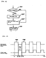
- Fig. 13 is a timing chart illustrating the operation of outputting driving pulses according to the sixth embodiment.
- a hour/minute hand driving pulse P HM1 is first output during a period from t1 to t2.
- hour/minute hand driving pulses and second hand driving pulses are alternately output in a similar manner such that there is no overlapping in the output timing.
- This allows the hour/minute hands and the second hand to be adjusted apparently at the same time to positions corresponding to the actual current time without causing a significant increase in the load imposed upon the power supply.
- the time adjusting can be performed while maintaining the power supply in a stable state.
- the hand driving direction in the time adjusting operation is selected each time adjusting is performed.
- a hand may be driven in a predetermined direction in the time adjusting operation.
- the power saving mode may include sub-modes, that is, a first power saving mode (in which only the second hand is stopped and the hour and minute hands are continued to be driven) and a second power saving mode (in which both the second hand and the hour/minute hands are stopped).
- time adjusting is performed for a time-measurement device having hour/minute hands and a second hand. Adjusting may also be performed for a time-measurement device having the calendar capability.
- the calendar driving part may be controlled in the adjusting operation in a similar manner as for the hour/minute driving part or the second hand driving part.
- the calendar driving part can be driven independently, that is, the calendar driving part includes a calendar driving motor.
- the period of time during which the load becomes too large can be minimized by setting the overlapping period of the driving timing within a predetermined range.
- the hour/minute hands and the second hands are driven, the hour hand, the minute hand, and the second hand may be driven separately in a similar manner as in the above-described embodiments without causing an increase in the load at a particular time.
- an electronic wristwatch may include a carrying state detection sensor for detecting whether the electronic wristwatch is being carried whereby the normal indication mode is employed when the electronic wristwatch is being carried and the power saving mode is employed when the electronic wristwatch is not carried.
- the carrying state detection sensor may be realized by an acceleration sensor for detecting the motion of a user, a contact sensor for detecting whether the wristwatch is worn by the user, or other types of sensors.
- the power supply device includes the electric power generator and the capacitor (electric power storage device).
- the invention is not limited to such a type of time-measurement device.
- the invention may also be applied to various time-measurement devices such as a time-measurement device including a primary battery, a time-measurement device including a secondary battery, and a clock device including both an electric power generator and a secondary battery.
- a first aspect of the invention provides a method of controlling a time-measurement device comprising: a power supply device for supplying electric power; time indication device including a plurality of indication hand driving parts for driving corresponding indication hands using electric power supplied by the power supply device so as to indicate time by the plurality of indication hands; a controller for switching the operating mode for each of the indication hand driving parts in accordance with a predetermined condition, between a power saving mode in which the corresponding indication hand is not driven and an indication mode in which the corresponding indication hand is continuously driven; and an elapsed-time memory for storing the time elapsed in the power saving mode; the method comprising a time adjusting step for adjusting indication of time by driving the indication hands using the indication hand driving part in accordance with the time elapsed in the power saving mode when the operating mode is changed from the power saving mode to the normal indication mode, wherein the time adjusting step includes a time adjusting operation control step for controlling the plurality of indication hand driving parts in the operation of adjusting the indication of time such that the pluralit
- an indication hand driving part whose driving speed in a normal driving operation is lower than that of the other indication hand driving parts may be driven to adjust the position of the associated hand preceding the other indication hand driving parts and then an indication hand driving part having a higher normal driving speed may be driven to adjust the position of the associated hand (second modification of the first aspect).
- an indication hand driving part whose driving speed in a normal driving operation is higher than that of the other indication hand driving parts may be driven to adjust the position of the associated hand preceding the other indication hand driving parts and then an indication hand driving part having a lower normal driving speed may be driven to adjust the position of the associated hand (third modification of the first aspect).
- condition is the state in which electric power is generated by the electric power generation means or the state in which electric energy is stored in the power supply means (fourth modification of the first aspect).
- the time-measurement device may further comprise carrying state detection means for detecting whether or not the time-measurement device is being carried, and the condition may be the state in which the time-measurement device is being carried (fifth modification of the first aspect).
- the prior art provides a method of controlling a time-measurement device comprising a power supply device for supplying electric power; a time indicating device including an indication hand driving device for driving an indication hand using electric power supplied by the power supply device so as to indicate time by the indication hand; a controller for switching the operating mode in accordance with a predetermined condition, between a power saving mode in which the corresponding indication hand is not driven and an indication mode in which the corresponding indication hand is continuously driven; and an elapsed-time memory for storing the time elapsed in the power saving mode; the method comprising a time adjusting step for adjusting indication of time by driving the indication hand using the indication hand driving device in accordance with the time elapsed in the power saving mode when the operating mode is switched from the power saving mode to the indication mode, wherein the time adjusting step includes an adjusting direction determination step for determining the direction in which the indication hand is driven to adjust the indication of time, in accordance with the time elapsed in the power saving mode.
- a direction in which the indication hand can be driven with less electric power than would be required to drive the indication hand in the opposite direction may be employed as the adjusting direction (first modification).
- a direction in which the indication hand can be driven in a shorter time than would be required to drive the indication hand in the opposite direction may be employed as the adjusting direction (second modification .
- the time adjusting operation may be performed such that the second hand is maintained at the position where the second hand has been at rest during the power saving mode until the time indicated by the second hand at rest becomes coincident with the actual current time, and driving of the second hand is started when the time indicated by the second hand at rest has become coincident with the actual current time (fourth modification).
- the indication hand when the angle between the hand position corresponding to the current time and the actual hand position is greater than a predetermined value, the indication hand may be driven to adjust the hand position in a direction opposite to the normal hand driving direction (sixth modification).
- the indication hand driving device may include a plurality of sub-indication hand driving devices for driving different indication hands, and, in the adjusting direction determination step, the adjusting direction may be determined for each of the plurality of sub-indication hand driving devices (seventh modification.
- the indication hand driving device may include a hour/minute hand driving device for driving a hour hand and a minute hand, and a second hand driving device for driving a second hand, in the adjusting direction determination step, the hand position adjusting direction may be determined for each of the hour/minute hand driving device and the second hand driving device (eighth modification).
- the hour/minute hand driving device may be driven preceding the second hand driving device, and the second hand driving device may be driven after completion of the driving of the hour and minute hands (ninth modification).
- the indication hand driving device may include a hour/minute hand driving device for driving a hour hand and a minute hand, a second hand driving device for driving a second hand, and a second hand driving device for driving a second hand, and in the adjusting direction determination step, the hand position adjusting direction may be determined for each of the hour hand driving device, the minute hand driving device, and the second hand driving device (tenth modification). Furthermore, in the tenth modification , when the indication of time is adjusted, the hour hand driving device, the minute hand driving device, and the second hand driving device may be driven in an exclusive fashion in the following order: hour hand driving device ⁇ minute hand driving device ⁇ second hand driving device.
- condition may be the state in which electric power is generated by the electric power generation means or the state in which electric energy is stored in the power supply means (eleventh modification).
- the time-measurement device may further comprise carrying state detection means for detecting whether or not the time-measurement device is being carried, and the condition may be the state in which the time-measurement device is being carried (twelfth modification).
- the timing of driving a plurality of indication hand driving parts is controlled such that the plurality of indication hand driving parts are driven in a predetermined order and such that the overlapping period of the adjusting operation period associated with the plurality of indication hand driving parts becomes less than a predetermined value.
- each hand is driven separately in a direction determined for each hand, thereby allowing the positions of the respective hands to be adjusted in a shorter time.
- the hour and minute hands are adjusted first by driving the hour/minute motor, and then the position of the second hand is adjusted so as to indicate the current time by driving the second motor.
- This allows the time adjusting operation to be performed under the stable condition in terms of the power supply voltage without encountering a failure in the operation due to the instability of the power supply voltage.
- the power consumption required to adjust the indication of time by driving the hands in the clockwise direction and the power consumption required to adjust the indication of time by driving the hands in the counterclockwise direction are compared with each other, and the hands are driven in a direction which results in less power consumption.
- the hands may also be driven in a direction which results in a shortest adjusting time thereby reducing the power consumption and the adjusting time.
Landscapes
- Physics & Mathematics (AREA)
- General Physics & Mathematics (AREA)
- Engineering & Computer Science (AREA)
- Power Engineering (AREA)
- Electromechanical Clocks (AREA)
- Electric Clocks (AREA)
Claims (14)
- Zeitmessvorrichtung (1), umfassend:ein Stromversorgungsmittel (A) zum Zuleiten von elektrischem Strom;ein Zeitangabemittel (D), das eine Mehrzahl von Angabezeigerantriebsteilen zum Antreiben entsprechender Angabezeiger unter Verwendung von elektrischem Strom, der von dem Stromversorgungsmittel (A) zugeleitet wird, enthält, so dass die Zeit von der Mehrzahl von Angabezeigern angezeigt wird;ein Steuermittel (C) zum Umschalten des Betriebsmodus für jedes der Angabezeigerantriebsteile in Übereinstimmung mit einem vorbestimmten Zustand zwischen einem Stromsparmodus, in dem der entsprechende Angabezeiger nicht angetrieben wird, und einem normalen Anzeigemodus, in dem der entsprechende Angabezeiger kontinuierlich angetrieben wird;ein Speichermittel für die verstrichene Zeit (96) zum Speichern der Zeit, die im Stromsparmodus verstrichen ist; undein Zeiteinstellungsmittel (300) zum Einstellen der Zeitangabe durch Antreiben der Angabezeiger unter Verwendung der Angabezeigerantriebsteile in Übereinstimmung mit der Zeit, die im Stromsparmodus verstrichen ist, wenn der Betriebsmodus vom Stromsparmodus in den normalen Anzeigemodus umgeschaltet wird, dadurch gekennzeichnet, dass:das Zeiteinstellungsmittel (300) ein Zeiteinstellungsbetriebssteuermittel zum Steuern der Zeitsteuerung des Antriebs der Angabezeigerantriebsteile in dem Betrieb zum Einstellen der Zeitanzeige enthält, so dass die Mehrzahl von Angabezeigerantriebsteilen in einer vorbestimmten Reihenfolge angetrieben wird und dass eine Überlappung unter Einstellungsbetriebsperioden der Mehrzahl von Angabezeigerantriebsteilen geringer als ein vorbestimmter Wert ist.
- Zeitmessvorrichtung (1) nach Anspruch 1, wobei das Zeiteinstellungsbetriebssteuermittel die Einstellungsbetriebsperioden für die Mehrzahl von Angabezeigerantriebsteilen so einstellt, dass es keine Überlappen zwischen den Betriebsperioden gibt.
- Zeitmessvorrichtung (1) nach Anspruch 1, wobei das Zeiteinstellungsmittel (300) die Zeitangabe so einstellt, dass von der Mehrzahl von Angabezeigerantriebsteilen ein Angabezeigerantriebsteil mit einer geringeren normalen Antriebsgeschwindigkeit zur Einstellung angetrieben wird, bevor ein Angabezeigerantriebsteil mit einer höheren normalen Antriebsgeschwindigkeit zur Einstellung angetrieben wird.
- Zeitmessvorrichtung (1) nach Anspruch 1, wobei das Zeiteinstellungsmittel (300) die Zeitangabe so einstellt, dass von der Mehrzahl von Angabezeigerantriebsteilen ein Angabezeigerantriebsteil mit einer höheren normalen Antriebsgeschwindigkeit zur Einstellung angetrieben wird, bevor ein Angabezeigerantriebsteil mit einer geringeren normalen Antriebsgeschwindigkeit zur Einstellung angetrieben wird.
- Zeitmessvorrichtung (1) nach Anspruch 1, wobei das Zeiteinstellungsmittel (300) die Zeitangabe so einstellt, dass ein Stunden-/Minutenzeigerantriebsmittel vor einem Sekundenzeigerantriebsmittel angetrieben wird, und das Sekundenzeigerantriebsmittel, nach Beendigung des Antriebs der Stunden- und Minutenzeiger angetrieben wird.
- Zeitmessvorrichtung (1) nach Anspruch 1, wobei, wenn das Zeiteinstellungsmittel (300) die Zeitangabe einstellt, das Zeiteinstellungsmittel die Mehrzahl von Zeigerantriebsteilen antreibt, indem es Antriebsimpulse an die Mehrzahl von Zeigerantriebsteilen ausgibt, so dass es zu keiner Überlappung in der Zeitsteuerung der Ausgabe der Antriebsimpulse kommt.
- Zeitmessvorrichtung (1) nach Anspruch 1, wobei, wenn das Zeiteinstellungsmittel (300) die Zeitangabe einstellt, das Zeiteinstellungsmittel (300) ein Stundenzeigerantriebsmittel, ein Minutenzeigerantriebsmittel und ein Sekundenzeigerantriebsmittel exklusive in der folgenden Reihenfolge antreibt:Stundenzeigerantriebsmittel → Minutenzeigerantriebsmittel → Sekundenzeigerantriebsmittel.
- Zeitmessvorrichtung (1) nach Anspruch 1, wobei das Stromversorgungsmittel (A) ein elektrisches Stromspeichermittel zum Speichern von elektrischer Energie enthält.
- Zeitmessvorrichtung (1) nach Anspruch 1, wobei das Stromversorgungsmittel (A) enthält:ein elektrisches Stromerzeugungsmittel zum Erzeugen elektrischen Stroms durch Umwandeln einer ersten Energie in eine zweite Energie in Form von elektrischer Energie; undein elektrisches Stromspeichermittel zum Speichern der erzeugten elektrischen Energie.
- Zeitmessvorrichtung (1) nach Anspruch 9, wobei die erste Energie eine Energie ist, die ausgewählt ist aus der Gruppe bestehend aus kinetischer Energie, Lichtenergie, Wärmeenergie, Druckenergie und elektromagnetischer Wellenenergie.
- Zeitmessvorrichtung (1) nach Anspruch wobei das Stromversorgungsmittel (A) eine primäre Batterie ist.
- Zeitmessvorrichtung (1) nach Anspruch 1, wobei der Zustand der Status ist, in dem elektrischer Strom von dem elektrischen Stromerzeugungsmittel erzeugt wird, oder der Status, in dem elektrische Energie in dem Stromversorgungsmittel (A) gespeichert ist.
- Zeitmessvorrichtung (1) nach Anspruch 1, des Weiteren umfassend ein Tragezustandsdetektionsmittel zum Erfassen, ob die Zeitmessvorrichtung getragen wird oder nicht; und
der Zustand der Status ist, in dem die Zeitmessvorrichtung getragen wird. - Verfahren zum Steuern einer Zeitmessvorrichtung, umfassend: eine Stromversorgungsvorrichtung (A) zum Zuleiten von elektrischem Strom; eine Zeitangabevorrichtung (D), die eine Mehrzahl von Angabezeigerantriebsteilen zum Antreiben entsprechender Angabezeiger unter Verwendung von elektrischem Strom, der von der Stromversorgungsvorrichtung zugeleitet wird, enthält, so dass die Zeit von der Mehrzahl von Angabezeigern angezeigt wird; eine Steuerung (C) zum Umschalten des Betriebsmodus für jedes der Angabezeigerantriebsteile in Übereinstimmung mit einem vorbestimmten Zustand zwischen einem Stromsparmodus, in dem der entsprechende Angabezeiger nicht angetrieben wird, und einem normalen Anzeigemodus, in dem der entsprechende Angabezeiger kontinuierlich angetrieben wird; und einen Speicher für die verstrichene Zeit zum Speichern der Zeit, die im Stromsparmodus verstrichen ist; und
wobei das Verfahren einen Zeiteinstellungsschritt umfasst zum Einstellen der Zeitangabe durch Antreiben der Angabezeiger unter Verwendung der Angabezeigerantriebsteile in Übereinstimmung mit der Zeit, die im Stromsparmodus verstrichen ist, wenn der Betriebsmodus vom Stromsparmodus in den normalen Anzeigemodus umgeschaltet wird, wobei das Verfahren dadurch gekennzeichnet ist, dass:
ein Zeiteinstellungsschritt einen Zeiteinstellungsbetriebssteuerschritt zum Steuern der Mehrzahl von Angabezeigerantriebsteilen in dem Betrieb zum Einstellen der Zeitanzeige enthält, so dass die Mehrzahl von Angabezeigerantriebsteilen in einer vorbestimmten Reihenfolge angetrieben wird und dass eine Überlappung unter Einstellungsbetriebsperioden der Mehrzahl von Angabezeigerantriebsteilen geringer als ein vorbestimmter Wert ist.
Applications Claiming Priority (4)
| Application Number | Priority Date | Filing Date | Title |
|---|---|---|---|
| JP35289498 | 1998-12-11 | ||
| JP35289498 | 1998-12-11 | ||
| JP28738299 | 1999-10-07 | ||
| JP28738299A JP3551861B2 (ja) | 1998-12-11 | 1999-10-07 | 計時装置及びその制御方法 |
Publications (3)
| Publication Number | Publication Date |
|---|---|
| EP1014227A2 EP1014227A2 (de) | 2000-06-28 |
| EP1014227A3 EP1014227A3 (de) | 2002-09-04 |
| EP1014227B1 true EP1014227B1 (de) | 2006-03-15 |
Family
ID=26556700
Family Applications (1)
| Application Number | Title | Priority Date | Filing Date |
|---|---|---|---|
| EP99309937A Expired - Lifetime EP1014227B1 (de) | 1998-12-11 | 1999-12-10 | Zeitmessvorrichtung und verfahren zu ihrer kontrolle |
Country Status (5)
| Country | Link |
|---|---|
| US (1) | US6367967B1 (de) |
| EP (1) | EP1014227B1 (de) |
| JP (1) | JP3551861B2 (de) |
| CN (1) | CN1135457C (de) |
| DE (1) | DE69930359T2 (de) |
Families Citing this family (23)
| Publication number | Priority date | Publication date | Assignee | Title |
|---|---|---|---|---|
| JP2001249192A (ja) | 1999-12-27 | 2001-09-14 | Seiko Epson Corp | 計時装置及び計時装置の制御方法 |
| EP1215545A1 (de) * | 2000-12-18 | 2002-06-19 | Asulab S.A. | Analoge elektronische Uhr mit Vorrichtung zur Zeitkorrektur nach einer mangelhaften Energiezufuhr |
| US7065006B2 (en) * | 2003-12-23 | 2006-06-20 | Timex Group B.V. | Method for enabling displayability/inhibitability of mode functions in a multimode electronic device |
| US7847421B2 (en) * | 2007-01-19 | 2010-12-07 | Willowview Systems, Inc. | System for generating electrical energy from ambient motion |
| US8023362B2 (en) | 2007-09-28 | 2011-09-20 | Casio Computer Co., Ltd. | Hand position detecting device and apparatus including the device |
| JP4596002B2 (ja) | 2007-12-25 | 2010-12-08 | カシオ計算機株式会社 | 針位置検出装置および針位置検出方法 |
| JP4623140B2 (ja) * | 2008-05-28 | 2011-02-02 | カシオ計算機株式会社 | 針位置検出装置および針位置検出制御方法 |
| JP5363167B2 (ja) * | 2008-05-29 | 2013-12-11 | セイコーインスツル株式会社 | ステッピングモータ制御回路及びアナログ電子時計 |
| JP4730397B2 (ja) * | 2008-05-30 | 2011-07-20 | カシオ計算機株式会社 | 針位置検出装置 |
| US8111033B2 (en) * | 2008-06-17 | 2012-02-07 | Seiko Instruments Inc. | Stepping motor control circuit and analog electronic timepiece |
| JP5212326B2 (ja) * | 2009-09-24 | 2013-06-19 | カシオ計算機株式会社 | アナログ電子時計 |
| JP5482181B2 (ja) * | 2009-12-18 | 2014-04-23 | カシオ計算機株式会社 | アナログ電子時計 |
| JP5906727B2 (ja) * | 2011-12-27 | 2016-04-20 | カシオ計算機株式会社 | アナログ電子時計 |
| JP5939852B2 (ja) * | 2012-03-22 | 2016-06-22 | エスアイアイ・セミコンダクタ株式会社 | アナログ電子時計 |
| TWI521337B (zh) * | 2014-05-06 | 2016-02-11 | 巨擘科技股份有限公司 | 計時器及其省電方法 |
| CN106575100B (zh) * | 2014-09-04 | 2020-08-25 | 索尼公司 | 信息显示装置和信息显示方法、程序以及通信系统 |
| JP2016200502A (ja) | 2015-04-10 | 2016-12-01 | セイコーエプソン株式会社 | 電子時計 |
| CN108052059B (zh) * | 2017-10-23 | 2019-11-01 | 天芯智能(深圳)股份有限公司 | 一种智能手表指针归零的方法、系统及智能手表 |
| JP7005412B2 (ja) * | 2018-03-30 | 2022-02-10 | シチズン時計株式会社 | アナログ電子時計 |
| CN109283830A (zh) * | 2018-11-20 | 2019-01-29 | 深圳智芯科技有限公司 | 一种减少走时误差的方法、系统和计时装置 |
| JP7221759B2 (ja) * | 2019-03-28 | 2023-02-14 | アズビル株式会社 | 時間計測回路 |
| CN111769768B (zh) * | 2020-05-29 | 2021-12-14 | 淮北微立淘科技有限公司 | 一种手表步进电机驱动补偿方法 |
| JP7552381B2 (ja) * | 2021-01-27 | 2024-09-18 | セイコーエプソン株式会社 | 電子時計および電子時計の制御方法 |
Family Cites Families (11)
| Publication number | Priority date | Publication date | Assignee | Title |
|---|---|---|---|---|
| JPS58176570A (ja) | 1982-04-09 | 1983-10-17 | Citizen Watch Co Ltd | 電子時計 |
| JPS5940290A (ja) * | 1982-08-31 | 1984-03-05 | Seiko Epson Corp | アナログ多機能時計 |
| JPS60147680A (ja) | 1984-01-13 | 1985-08-03 | Citizen Watch Co Ltd | 秒帰零付指針式電子時計 |
| JPS61202186A (ja) | 1985-03-05 | 1986-09-06 | Seiko Instr & Electronics Ltd | 電子時計 |
| CH665081GA3 (de) * | 1985-10-11 | 1988-04-29 | ||
| WO1989006387A1 (fr) * | 1987-12-25 | 1989-07-13 | Citizen Watch Co., Ltd. | Affichage utilisant un pointeur |
| US5113381A (en) * | 1989-04-19 | 1992-05-12 | Seiko Epson Corporation | Multifunction electronic analog timepiece |
| JPH037833A (ja) | 1989-06-05 | 1991-01-16 | Mitsubishi Electric Corp | 熱輸送装置 |
| JP2577839B2 (ja) * | 1991-10-02 | 1997-02-05 | リズム時計工業株式会社 | アナログ時計装置 |
| JPH0666962A (ja) * | 1992-07-02 | 1994-03-11 | Seiko Instr Inc | ページャ付電子時計 |
| JP3041351B2 (ja) * | 1993-03-16 | 2000-05-15 | セイコーインスツルメンツ株式会社 | クロノグラフ機能付アナログ電子時計 |
-
1999
- 1999-10-07 JP JP28738299A patent/JP3551861B2/ja not_active Expired - Fee Related
- 1999-12-03 US US09/454,479 patent/US6367967B1/en not_active Expired - Lifetime
- 1999-12-10 DE DE69930359T patent/DE69930359T2/de not_active Expired - Lifetime
- 1999-12-10 EP EP99309937A patent/EP1014227B1/de not_active Expired - Lifetime
- 1999-12-10 CN CNB991267494A patent/CN1135457C/zh not_active Expired - Fee Related
Also Published As
| Publication number | Publication date |
|---|---|
| CN1135457C (zh) | 2004-01-21 |
| DE69930359D1 (de) | 2006-05-11 |
| DE69930359T2 (de) | 2006-10-19 |
| US6367967B1 (en) | 2002-04-09 |
| HK1028818A1 (en) | 2001-03-02 |
| CN1259691A (zh) | 2000-07-12 |
| JP2000230987A (ja) | 2000-08-22 |
| EP1014227A3 (de) | 2002-09-04 |
| EP1014227A2 (de) | 2000-06-28 |
| JP3551861B2 (ja) | 2004-08-11 |
Similar Documents
| Publication | Publication Date | Title |
|---|---|---|
| EP1014227B1 (de) | Zeitmessvorrichtung und verfahren zu ihrer kontrolle | |
| JP2000235088A (ja) | 携帯用電子機器および携帯用電子機器の制御方法 | |
| US6396772B1 (en) | Electronic apparatus and control method for electronic apparatus | |
| US6956794B2 (en) | Electronically controlled timepiece, and power supply control method and time correction method therefore | |
| US6327225B1 (en) | Electronic unit, and control method for electronic unit | |
| JP3534071B2 (ja) | 電子機器及び電子機器の制御方法 | |
| US6476580B1 (en) | Electronic apparatus and control method for electronic apparatus | |
| JP3601376B2 (ja) | 電子機器及び電子機器の制御方法 | |
| JPWO2000059091A1 (ja) | 電子機器及び電子機器の制御方法 | |
| JPWO2000036474A1 (ja) | 電子機器および電子機器の制御方法 | |
| JP3601375B2 (ja) | 携帯用電子機器及び携帯用電子機器の制御方法 | |
| JP3830289B2 (ja) | 電子機器および計時装置 | |
| US20010046188A1 (en) | Electronically controlled mechanical timepiece and method controlling the same | |
| US6630852B2 (en) | Power-generation detection circuit for use in an electronic device and power-generation detection method and power consumption control method for use in connection therewith | |
| JP3654018B2 (ja) | 計時装置および計時装置の制御方法 | |
| WO2000070411A1 (fr) | Materiel electronique et son procede de commande | |
| HK1028818B (en) | Time-measurement device and method of controlling the same | |
| JP4349388B2 (ja) | 電子機器、電子機器の制御方法、計時装置、および計時装置の制御方法 | |
| JP2002323578A (ja) | 計時装置及びその制御方法 | |
| EP4439197A1 (de) | Mechanische uhr mit mechanischem uhrwerk und einer elektronischen geschwindigkeitsregelung. | |
| JP4055446B2 (ja) | 電子機器、電子機器の制御方法、計時装置、および計時装置の制御方法 | |
| JP2002156474A (ja) | 電子機器及び電子機器の制御方法 | |
| HK1033005A (en) | Electronic device, and method for controlling the electronic device | |
| JP2002328188A (ja) | 携帯用電子機器及び携帯用電子機器の制御方法 | |
| JP2002277567A (ja) | 電子機器及び電子機器の制御方法 |
Legal Events
| Date | Code | Title | Description |
|---|---|---|---|
| PUAI | Public reference made under article 153(3) epc to a published international application that has entered the european phase |
Free format text: ORIGINAL CODE: 0009012 |
|
| AK | Designated contracting states |
Kind code of ref document: A2 Designated state(s): AT BE CH CY DE DK ES FI FR GB GR IE IT LI LU MC NL PT SE |
|
| AX | Request for extension of the european patent |
Free format text: AL;LT;LV;MK;RO;SI |
|
| PUAL | Search report despatched |
Free format text: ORIGINAL CODE: 0009013 |
|
| AK | Designated contracting states |
Kind code of ref document: A3 Designated state(s): AT BE CH CY DE DK ES FI FR GB GR IE IT LI LU MC NL PT SE |
|
| AX | Request for extension of the european patent |
Free format text: AL;LT;LV;MK;RO;SI |
|
| 17P | Request for examination filed |
Effective date: 20030205 |
|
| AKX | Designation fees paid |
Designated state(s): CH DE FR GB LI |
|
| 17Q | First examination report despatched |
Effective date: 20041221 |
|
| GRAP | Despatch of communication of intention to grant a patent |
Free format text: ORIGINAL CODE: EPIDOSNIGR1 |
|
| GRAS | Grant fee paid |
Free format text: ORIGINAL CODE: EPIDOSNIGR3 |
|
| GRAA | (expected) grant |
Free format text: ORIGINAL CODE: 0009210 |
|
| AK | Designated contracting states |
Kind code of ref document: B1 Designated state(s): CH DE FR GB LI |
|
| REG | Reference to a national code |
Ref country code: GB Ref legal event code: FG4D Ref country code: CH Ref legal event code: EP |
|
| REG | Reference to a national code |
Ref country code: CH Ref legal event code: NV Representative=s name: PATENTANWAELTE SCHAAD, BALASS, MENZL & PARTNER AG |
|
| REF | Corresponds to: |
Ref document number: 69930359 Country of ref document: DE Date of ref document: 20060511 Kind code of ref document: P |
|
| ET | Fr: translation filed | ||
| REG | Reference to a national code |
Ref country code: HK Ref legal event code: GR Ref document number: 1028818 Country of ref document: HK |
|
| PLBE | No opposition filed within time limit |
Free format text: ORIGINAL CODE: 0009261 |
|
| STAA | Information on the status of an ep patent application or granted ep patent |
Free format text: STATUS: NO OPPOSITION FILED WITHIN TIME LIMIT |
|
| 26N | No opposition filed |
Effective date: 20061218 |
|
| PGFP | Annual fee paid to national office [announced via postgrant information from national office to epo] |
Ref country code: DE Payment date: 20141202 Year of fee payment: 16 Ref country code: GB Payment date: 20141210 Year of fee payment: 16 Ref country code: CH Payment date: 20141212 Year of fee payment: 16 |
|
| PGFP | Annual fee paid to national office [announced via postgrant information from national office to epo] |
Ref country code: FR Payment date: 20141208 Year of fee payment: 16 |
|
| REG | Reference to a national code |
Ref country code: DE Ref legal event code: R119 Ref document number: 69930359 Country of ref document: DE |
|
| REG | Reference to a national code |
Ref country code: CH Ref legal event code: PL |
|
| GBPC | Gb: european patent ceased through non-payment of renewal fee |
Effective date: 20151210 |
|
| REG | Reference to a national code |
Ref country code: FR Ref legal event code: ST Effective date: 20160831 |
|
| PG25 | Lapsed in a contracting state [announced via postgrant information from national office to epo] |
Ref country code: GB Free format text: LAPSE BECAUSE OF NON-PAYMENT OF DUE FEES Effective date: 20151210 Ref country code: DE Free format text: LAPSE BECAUSE OF NON-PAYMENT OF DUE FEES Effective date: 20160701 Ref country code: LI Free format text: LAPSE BECAUSE OF NON-PAYMENT OF DUE FEES Effective date: 20151231 Ref country code: CH Free format text: LAPSE BECAUSE OF NON-PAYMENT OF DUE FEES Effective date: 20151231 |
|
| PG25 | Lapsed in a contracting state [announced via postgrant information from national office to epo] |
Ref country code: FR Free format text: LAPSE BECAUSE OF NON-PAYMENT OF DUE FEES Effective date: 20151231 |