EP1014235A2 - Dispositif d'affichage du temps - Google Patents
Dispositif d'affichage du temps Download PDFInfo
- Publication number
- EP1014235A2 EP1014235A2 EP99309209A EP99309209A EP1014235A2 EP 1014235 A2 EP1014235 A2 EP 1014235A2 EP 99309209 A EP99309209 A EP 99309209A EP 99309209 A EP99309209 A EP 99309209A EP 1014235 A2 EP1014235 A2 EP 1014235A2
- Authority
- EP
- European Patent Office
- Prior art keywords
- time
- display device
- utc
- area
- location
- Prior art date
- Legal status (The legal status is an assumption and is not a legal conclusion. Google has not performed a legal analysis and makes no representation as to the accuracy of the status listed.)
- Withdrawn
Links
Images



Classifications
-
- G—PHYSICS
- G04—HOROLOGY
- G04G—ELECTRONIC TIME-PIECES
- G04G9/00—Visual time or date indication means
- G04G9/0076—Visual time or date indication means in which the time in another time-zone or in another city can be displayed at will
-
- G—PHYSICS
- G04—HOROLOGY
- G04R—RADIO-CONTROLLED TIME-PIECES
- G04R20/00—Setting the time according to the time information carried or implied by the radio signal
- G04R20/02—Setting the time according to the time information carried or implied by the radio signal the radio signal being sent by a satellite, e.g. GPS
- G04R20/06—Decoding time data; Circuits therefor
Definitions
- the present invention relates generally to a time display device, and more particularly, to a time display device adapted for movement between different time zones.
- Set time differs by country and by zone. That is, time is set by each country and region based on Greenwich Mean Time, which is universal standard time. Accordingly, there are time differences between countries and zones.
- Portable time display devices such as wristwatches and other such devices that display the time move with the user. If the user moves from one time zone to a different time zone it is necessary for the user to set the wristwatch to the local time.
- a more specific object of the present invention is to provide a time display device that sets the local time correctly without the need for the user to perform some operation.
- a time display device having location detecting means for detecting a location of the time display device and clocking means for counting time, the time display device comprising: time adjusting means for adjusting the counted time of the clocking means to match a local time of the location detected by the location detecting means.
- the location detecting means detects the current location and the counted time of the clocking means is automatically adjusted to a time at the current location so detected, that is, the local time, so it is not necessary for the user to perform some operation to adjust the time of the time display device to the local time.
- time adjusting means comprises:
- time display device as described above, wherein the location detecting means acquires location information via a global positioning system (GPS) and the UTC obtaining means obtains the UTC according to a GPS time obtained from the GPS.
- GPS global positioning system
- obtaining the UTC is made easier by using the GPS time.
- time adjusting means comprises:
- a current time of a selected area can be computed and displayed.
- time display device as described above, embodied as a portable time display device.
- the above-described objects of the present invention are also achieved by the time display device as described above, wherein the portable time display device comprises a wristwatch.
- the counted time of the time display device is automatically adjusted to local time even as the user moves from one time zone to a different time zone.
- the above-described objects of the present invention are also achieved by the time display device as described above, wherein a battery cell is provided in a band portion of the wristwatch.
- FIG. 1 is a perspective view of an embodiment of the present invention.
- the time display device 1 of the present invention is embodied as a wristwatch.
- the wristwatch type time display device 1 of the present embodiment comprises a time display device main unit 2, hereinafter referred to as the main unit 2, and a band part 3.
- a case of the main unit 2 contains a GPS location detector not shown in the diagram and a clocking part for counting time.
- a display unit 4 On the front surface of the main unit 2, which is substantially circular in shape, a display unit 4 is formed. As will be explained later, the display unit 4 displays location information, such as the longitude and latitude, as well as the time of the current location according to the location information.
- a GPS antenna 5 is arranged along an inner periphery of the display unit 4 of the main unit 2.
- input buttons 12 are arranged on a surface of the display unit 4. These input buttons 12 comprise a mode switching button 6, an enter button 7, an up button 8, a down button 9, a left button 10 and a right button 11.
- the band part 3 is attached to a top and bottom of the main unit 2, and is used to hold the main unit 2 in place on the user's wrist.
- a battery cell 13 is built into the band part 3. The battery cell 13 is used to power the main unit 2.
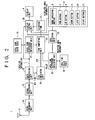
- FIG. 2 is a block diagram of an embodiment of the present invention.
- a high-frequency unit 14, signal processing device 15, data processing unit 16, local time difference obtaining unit 17, a local time value table 18, a coordinated universal time (UTC) obtaining means 19, a time computing unit 20, a clocking unit 21, an area selection unit 22, an area time difference obtaining unit 23, an area time value table 24 and a display control unit 25 are built into the main unit 2 of the time display device 1, and are coupled to the display unit 4, the GPS antenna 5 and the input buttons 12.
- the GPS antenna 5 is composed of a loop antenna arranged, as noted previously, along the inner periphery of the case. A signal received at the GPS antenna 5 is supplied to the high-frequency unit 14.
- the high-frequency unit 14 amplifies and frequency-converts the signal from the GPS satellite from the signal received at the GPS antenna 5.
- the signal amplified and frequency-converted by the high-frequency unit 14 is supplied to the signal processing unit 15.
- the signal processing unit 15 performs predetermined signal processing such as demodulation and AD conversion of the signal amplified and frequency-converted by the high-frequency unit 14, and obtains GPS data.
- the GPS data obtained by the signal processing unit 15 is supplied to the data processing unit 16.
- the data processing unit 16 Based on the GPS data supplied from the signal processing unit 15, the data processing unit 16 obtains GPS time as well as location information such as latitude, longitude and elevation. The location information obtained by the data processing unit 16 is supplied to the local time difference obtaining unit 17 as well as the display control unit 25. In addition, the GPS time obtained by the data processing unit 16 is supplied to the UTC obtaining means 19.
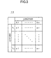
- the local time difference obtaining unit 17 is connected to the local time value table 18. Local time values corresponding to location information are stored in the local time value table 18. The local time difference obtaining unit 17 searches the local time value table 18 and extracts a local time value corresponding to the location information supplied from the data processing unit 16. Local time values al through ar, for example, denote time differences from UTC.
- FIG. 3 is a schematic table of local time values according to an embodiment of the present invention. As shown in the diagram, local time values al through ar corresponding to latitude and longitude are set in the local time value table 18.
- the local time difference obtaining unit 17 searches the local time value table 18, extracts a local time value al and outputs that local time value al to the time computing unit 20.
- the local time difference obtaining unit 17 searches the local time value table 18, extracts a local time value ar and outputs that local time value ar.
- the values al through ar set in the local time value table 18 are preset for individual regions divided according to latitude and longitude and are also divided so that individual regions using the same time are grouped together.
- FIG. 4 is a diagram showing the distribution of local time values according to an embodiment of the present invention.
- local time values al through ar are set for individual regions divided according to latitude and longitude.
- the local time value table 18 is searched by the local time difference obtaining unit 17 according to the location information longitude and latitude of the data processing unit 16 and a given value al through ar is selected. That given value al through ar selected and output by the local time difference obtaining unit 17 is supplied to the time computing unit 20.
- the UTC obtaining means 19 obtains the UTC.
- UTC is the mean solar time at the Greenwich meridian.
- a reference time is obtained.
- the UTC obtained by the UTC obtaining means 19 is supplied to the time computing unit 20.
- the time computing unit 20 is also supplied with the UTC from the UTC obtaining means 19.
- the time computing unit 20 computes the local current time by adding the given value al through ar obtained by the local time difference obtaining unit 17, that is, the time difference from UTC, to the UTC supplied from the UTC obtaining means.
- the local current time computed by the time computing unit 20 is supplied to the clocking unit 21.
- the clocking unit 21 takes the local current time computed by the time computing unit 20 and counts it. The counted time is then supplied to the supply control unit 25.
- the display control unit 25 is also supplied with a switching control signal from the input buttons 12.
- the display control unit 25 selectively outputs either location information from the data processing unit 16 or counted time from the clocking unit 21 in response to the switching control signal supplied from the input buttons 12.
- the location information or counted time selectively output by the display control unit 25 is supplied to the display unit 4.
- the display unit 4 which may be composed of an LCD or similar device, displays the location information or counted time supplied from the display control unit 25.
- the input buttons 12 comprise a mode switching button 6, an enter button 7, an up button 8, a down button 9, a left button 10 and a right button 11.
- the mode switching button 6 is used when switching the display mode between location information and time and for switching to a selection mode for selecting an area.
- the enter button 7 is used when inputting an area selected in the selection mode.
- the up button 8, down button 9, left button 10 and right button 11 are used when selecting a counted time area.
- the area selection unit 22 When the selection mode is selected using the mode switching button 6, the area selection unit 22 is activated and supplies selected area information to the display control unit 25.
- the display control unit 25 displays an area name according to the selected area information supplied from the area selection unit 22 when the selection mode is selected.
- the area selection unit 22 successively changes the selected area information supplied to the display control unit 25 when the up button 8, down button 9, left button 10 and right button 11 are pressed.
- the user presses the enter button 7 when the name of the area for which time display is sought is displayed.
- the area selection unit 22 supplies the displayed area information supplied to the display control unit 25 to the area time difference obtaining unit 23 as selected area information.
- the area time difference obtaining unit 23 references the area time value table 24 and extracts from the area time value table 24 an area time value corresponding to the selected area information supplied from the area selection unit 22.
- the area time values al through ar are the same as the local time values al through ar set in the local time value table 18, and represent the time difference from UTC.
- FIG. 5 is a schematic conversion table for converting local time values into local time differences according to an embodiment of the present invention.
- the area time value table 24 the values al through ar are set for each area name, for example, a country name or a city name.
- the area time difference obtaining unit 23 extracts an area time value corresponding to the country name or city name corresponding to the selected area information selected by the area selection unit 22 from the area time value table 24 shown in FIG. 5.
- the time computing unit 20 computes the local current time by adding the given value al through ar obtained by the local time difference obtaining unit 17, that is, the time difference from UTC, to the UTC supplied from the UTC obtaining means.
- the local current time computed by the time computing unit 20 is supplied to the clocking unit 21.
- the clocking unit 21 takes the local current time computed by the time computing unit 20 and counts it. The counted time is then supplied to the supply control unit 25.
- the time computing unit 20 computes the current time of the selected area by adding the given value al through ar obtained by the area time difference obtaining unit 23, that is, the time difference from UTC, to the UTC supplied from the UTC obtaining means.
- the current time of the selected area computed by the time computing unit 20 is supplied to the clocking unit 21.
- the clocking unit 21 takes the current time of the selected area computed by the time computing unit 20 and counts it. The counted time of the selected area is then supplied to the supply control unit 25.
- the control display unit 25 controls the display unit 4 so that a counted time corresponding to the counted time of the selected area supplied from the clocking unit 21 is displayed by the display unit 4.
Landscapes
- Physics & Mathematics (AREA)
- General Physics & Mathematics (AREA)
- Engineering & Computer Science (AREA)
- Radar, Positioning & Navigation (AREA)
- Remote Sensing (AREA)
- Electric Clocks (AREA)
- Position Fixing By Use Of Radio Waves (AREA)
Applications Claiming Priority (2)
| Application Number | Priority Date | Filing Date | Title |
|---|---|---|---|
| JP36559398A JP2000187088A (ja) | 1998-12-22 | 1998-12-22 | 計時装置 |
| JP36559398 | 1998-12-22 |
Publications (2)
| Publication Number | Publication Date |
|---|---|
| EP1014235A2 true EP1014235A2 (fr) | 2000-06-28 |
| EP1014235A3 EP1014235A3 (fr) | 2002-09-18 |
Family
ID=18484655
Family Applications (1)
| Application Number | Title | Priority Date | Filing Date |
|---|---|---|---|
| EP19990309209 Withdrawn EP1014235A3 (fr) | 1998-12-22 | 1999-11-18 | Dispositif d'affichage du temps |
Country Status (2)
| Country | Link |
|---|---|
| EP (1) | EP1014235A3 (fr) |
| JP (1) | JP2000187088A (fr) |
Cited By (8)
| Publication number | Priority date | Publication date | Assignee | Title |
|---|---|---|---|---|
| GB2379132A (en) * | 2001-08-22 | 2003-02-26 | Inventec Appliances Corp | Using global positioning in a mobile telephone to update system time |
| EP1884842A1 (fr) * | 2006-07-31 | 2008-02-06 | Seiko Epson Corporation | Dispositif de correction de l'heure, appareil horaire doté d'un dispositif de correction de l'heure et procédé de correction de l'heure |
| US7391677B2 (en) | 2006-07-31 | 2008-06-24 | Seiko Epson Corporation | Positioning device, positioning method, and timepiece having the positioning device |
| EP2065768A3 (fr) * | 2007-11-27 | 2009-06-17 | Seiko Epson Corporation | Horloge électronique, procédé de réglage de l'heure pour une horloge électronique, et programme de contrôle pour une horloge électronique |
| US7715279B2 (en) | 2006-07-31 | 2010-05-11 | Seiko Epson Corporation | Time correction device, timepiece having a time correction device, and time correction method |
| EP2085835A3 (fr) * | 2008-01-29 | 2010-08-25 | Seiko Epson Corporation | Piece d'horlogerie électronique et son procédé de réglage du temps |
| EP2522002A4 (fr) * | 2010-01-07 | 2016-08-17 | Qualcomm Inc | Détermination d'un fuseau horaire et passage à l'heure d'été |
| US20170357222A1 (en) * | 2014-12-26 | 2017-12-14 | Citizen Holdings Co., Ltd. | Satellite radio-controlled watch |
Families Citing this family (2)
| Publication number | Priority date | Publication date | Assignee | Title |
|---|---|---|---|---|
| JP3538176B2 (ja) | 2001-11-28 | 2004-06-14 | 株式会社東芝 | 電子機器およびその制御方法 |
| JP5169919B2 (ja) * | 2009-03-06 | 2013-03-27 | セイコーエプソン株式会社 | 電子機器、時差データ取得方法、時差データのデータ構造 |
Family Cites Families (4)
| Publication number | Priority date | Publication date | Assignee | Title |
|---|---|---|---|---|
| EP0498199A3 (en) * | 1991-02-04 | 1993-01-13 | Motorola, Inc. | Satellite signal receiver with automatic time of day information |
| WO1995027927A1 (fr) * | 1994-04-08 | 1995-10-19 | Celestial Time, Inc. | Montre commandee par satellite |
| DE29610011U1 (de) * | 1996-06-07 | 1997-10-09 | Hansen, Lars, 45239 Essen | Digitale Armbanduhr und digitale Anzeigeeinrichtung |
| US5982710A (en) * | 1997-03-14 | 1999-11-09 | Rawat; Prem P. | Method and apparatus for providing time using cartesian coordinates |
-
1998
- 1998-12-22 JP JP36559398A patent/JP2000187088A/ja active Pending
-
1999
- 1999-11-18 EP EP19990309209 patent/EP1014235A3/fr not_active Withdrawn
Cited By (14)
| Publication number | Priority date | Publication date | Assignee | Title |
|---|---|---|---|---|
| GB2379132A (en) * | 2001-08-22 | 2003-02-26 | Inventec Appliances Corp | Using global positioning in a mobile telephone to update system time |
| US7715279B2 (en) | 2006-07-31 | 2010-05-11 | Seiko Epson Corporation | Time correction device, timepiece having a time correction device, and time correction method |
| EP1884842A1 (fr) * | 2006-07-31 | 2008-02-06 | Seiko Epson Corporation | Dispositif de correction de l'heure, appareil horaire doté d'un dispositif de correction de l'heure et procédé de correction de l'heure |
| US7391677B2 (en) | 2006-07-31 | 2008-06-24 | Seiko Epson Corporation | Positioning device, positioning method, and timepiece having the positioning device |
| US7474594B2 (en) | 2006-07-31 | 2009-01-06 | Seiko Epson Corporation | Time correction device, timepiece having a time correction device, and time correction method |
| US8493816B2 (en) | 2007-11-27 | 2013-07-23 | Seiko Epson Corporation | Electronic timepiece, time adjustment method for an electronic timepiece, and control program for an electronic timepiece |
| US8077550B2 (en) | 2007-11-27 | 2011-12-13 | Seiko Epson Corporation | Electronic timepiece, time adjustment method for an electronic timepiece, and control program for an electronic timepiece |
| CN101446802B (zh) * | 2007-11-27 | 2011-12-14 | 精工爱普生株式会社 | 电子钟表、电子钟表的时刻校正方法和控制方法 |
| EP2065768A3 (fr) * | 2007-11-27 | 2009-06-17 | Seiko Epson Corporation | Horloge électronique, procédé de réglage de l'heure pour une horloge électronique, et programme de contrôle pour une horloge électronique |
| EP2085835A3 (fr) * | 2008-01-29 | 2010-08-25 | Seiko Epson Corporation | Piece d'horlogerie électronique et son procédé de réglage du temps |
| US8705321B2 (en) | 2008-01-29 | 2014-04-22 | Seiko Epson Corporation | Electronic timepiece and time adjustment method for an electronic timepiece |
| EP2522002A4 (fr) * | 2010-01-07 | 2016-08-17 | Qualcomm Inc | Détermination d'un fuseau horaire et passage à l'heure d'été |
| US20170357222A1 (en) * | 2014-12-26 | 2017-12-14 | Citizen Holdings Co., Ltd. | Satellite radio-controlled watch |
| US10496044B2 (en) * | 2014-12-26 | 2019-12-03 | Citizen Watch Co., Ltd. | Satellite radio-controlled watch |
Also Published As
| Publication number | Publication date |
|---|---|
| EP1014235A3 (fr) | 2002-09-18 |
| JP2000187088A (ja) | 2000-07-04 |
Similar Documents
| Publication | Publication Date | Title |
|---|---|---|
| JP4462338B2 (ja) | 電子時計、電子時計の時刻修正方法、電子時計の制御プログラム | |
| EP2093634B1 (fr) | Dispositif de réception de signaux satellites et procédé de commande pour dispositif de réception de signaux satellites | |
| US9563174B2 (en) | Electronic device, time correction method, and time correction program | |
| US8705321B2 (en) | Electronic timepiece and time adjustment method for an electronic timepiece | |
| US9766595B2 (en) | Timepiece and electronic timepiece | |
| JP3743819B2 (ja) | 時計機能付電子機器、時刻情報補正方法 | |
| EP2916178B1 (fr) | Appareil et mouvement d'horlogerie électronique | |
| JP5392177B2 (ja) | 電子機器 | |
| US8188916B2 (en) | Position/time detecting apparatus and timepiece including the apparatus | |
| KR20010031512A (ko) | 시각 출력 장치 및 시각 교정 방법 | |
| EP3065007B1 (fr) | Dispositif électronique et procédé de commande associé | |
| US20060274605A1 (en) | Portable electronic device with radiofrequency signal receiver and method for determining the position of the same | |
| US20060239123A1 (en) | Daylight saving time automatic adjustment method and timepiece using same | |
| JP5435167B2 (ja) | 衛星信号受信装置および衛星信号受信装置の制御方法 | |
| JP2000187088A (ja) | 計時装置 | |
| JP2019163997A (ja) | 衛星信号受信装置、電子機器および衛星信号受信装置の制御方法 | |
| KR101410225B1 (ko) | 이슬람 신도용 시계 | |
| JP2010217004A (ja) | 電子機器および電子機器の制御方法 | |
| JP2005069710A (ja) | 時刻表示装置 | |
| JP7167452B2 (ja) | 電子機器及び受信制御方法 | |
| JPH04370790A (ja) | 電子時計および表示制御方法 | |
| EP0962841A1 (fr) | Pièce d'horlogerie électronique et méthode d'affichage pour pièce d'horlogerie électronique | |
| JPH0996692A (ja) | 時計装置 |
Legal Events
| Date | Code | Title | Description |
|---|---|---|---|
| PUAI | Public reference made under article 153(3) epc to a published international application that has entered the european phase |
Free format text: ORIGINAL CODE: 0009012 |
|
| AK | Designated contracting states |
Kind code of ref document: A2 Designated state(s): AT BE CH CY DE DK ES FI FR GB GR IE IT LI LU MC NL PT SE |
|
| AX | Request for extension of the european patent |
Free format text: AL;LT;LV;MK;RO;SI |
|
| PUAL | Search report despatched |
Free format text: ORIGINAL CODE: 0009013 |
|
| AK | Designated contracting states |
Kind code of ref document: A3 Designated state(s): AT BE CH CY DE DK ES FI FR GB GR IE IT LI LU MC NL PT SE |
|
| AX | Request for extension of the european patent |
Free format text: AL;LT;LV;MK;RO;SI |
|
| STAA | Information on the status of an ep patent application or granted ep patent |
Free format text: STATUS: THE APPLICATION IS DEEMED TO BE WITHDRAWN |
|
| 18D | Application deemed to be withdrawn |
Effective date: 20020531 |