EP1014264A2 - Système et méthode pour faciliter la synchronisation à des points sûrs dans un système d'ordinateur à plusieurs fils d'exécution - Google Patents
Système et méthode pour faciliter la synchronisation à des points sûrs dans un système d'ordinateur à plusieurs fils d'exécution Download PDFInfo
- Publication number
- EP1014264A2 EP1014264A2 EP99309854A EP99309854A EP1014264A2 EP 1014264 A2 EP1014264 A2 EP 1014264A2 EP 99309854 A EP99309854 A EP 99309854A EP 99309854 A EP99309854 A EP 99309854A EP 1014264 A2 EP1014264 A2 EP 1014264A2
- Authority
- EP
- European Patent Office
- Prior art keywords
- thread
- safepoint
- region
- transition
- threads
- Prior art date
- Legal status (The legal status is an assumption and is not a legal conclusion. Google has not performed a legal analysis and makes no representation as to the accuracy of the status listed.)
- Granted
Links
Images



Classifications
-
- G—PHYSICS
- G06—COMPUTING OR CALCULATING; COUNTING
- G06F—ELECTRIC DIGITAL DATA PROCESSING
- G06F9/00—Arrangements for program control, e.g. control units
- G06F9/06—Arrangements for program control, e.g. control units using stored programs, i.e. using an internal store of processing equipment to receive or retain programs
- G06F9/46—Multiprogramming arrangements
- G06F9/52—Program synchronisation; Mutual exclusion, e.g. by means of semaphores
-
- G—PHYSICS
- G06—COMPUTING OR CALCULATING; COUNTING
- G06F—ELECTRIC DIGITAL DATA PROCESSING
- G06F9/00—Arrangements for program control, e.g. control units
- G06F9/06—Arrangements for program control, e.g. control units using stored programs, i.e. using an internal store of processing equipment to receive or retain programs
- G06F9/46—Multiprogramming arrangements
- G06F9/52—Program synchronisation; Mutual exclusion, e.g. by means of semaphores
- G06F9/522—Barrier synchronisation
-
- G—PHYSICS
- G06—COMPUTING OR CALCULATING; COUNTING
- G06F—ELECTRIC DIGITAL DATA PROCESSING
- G06F9/00—Arrangements for program control, e.g. control units
- G06F9/06—Arrangements for program control, e.g. control units using stored programs, i.e. using an internal store of processing equipment to receive or retain programs
- G06F9/46—Multiprogramming arrangements
- G06F9/52—Program synchronisation; Mutual exclusion, e.g. by means of semaphores
- G06F9/526—Mutual exclusion algorithms
-
- Y—GENERAL TAGGING OF NEW TECHNOLOGICAL DEVELOPMENTS; GENERAL TAGGING OF CROSS-SECTIONAL TECHNOLOGIES SPANNING OVER SEVERAL SECTIONS OF THE IPC; TECHNICAL SUBJECTS COVERED BY FORMER USPC CROSS-REFERENCE ART COLLECTIONS [XRACs] AND DIGESTS
- Y10—TECHNICAL SUBJECTS COVERED BY FORMER USPC
- Y10S—TECHNICAL SUBJECTS COVERED BY FORMER USPC CROSS-REFERENCE ART COLLECTIONS [XRACs] AND DIGESTS
- Y10S707/00—Data processing: database and file management or data structures
- Y10S707/99951—File or database maintenance
- Y10S707/99952—Coherency, e.g. same view to multiple users
- Y10S707/99953—Recoverability
-
- Y—GENERAL TAGGING OF NEW TECHNOLOGICAL DEVELOPMENTS; GENERAL TAGGING OF CROSS-SECTIONAL TECHNOLOGIES SPANNING OVER SEVERAL SECTIONS OF THE IPC; TECHNICAL SUBJECTS COVERED BY FORMER USPC CROSS-REFERENCE ART COLLECTIONS [XRACs] AND DIGESTS
- Y10—TECHNICAL SUBJECTS COVERED BY FORMER USPC
- Y10S—TECHNICAL SUBJECTS COVERED BY FORMER USPC CROSS-REFERENCE ART COLLECTIONS [XRACs] AND DIGESTS
- Y10S707/00—Data processing: database and file management or data structures
- Y10S707/99951—File or database maintenance
- Y10S707/99956—File allocation
- Y10S707/99957—Garbage collection
Definitions
- the present invention relates to the facilitation of a global safepoint operation in a multithreaded computer system environment.
- the present invention relates to facilitating a global safepoint operation while avoiding suspending all threads during safepoint synchronization.
- multitasking refers to an operating system's ability to support multiprocesses simultaneously.
- a process is typically a program in execution. Support for multiple processes is necessary in applications where several computations proceed in parallel.
- time-sharing systems multiple users share a single computer system and all processes created by them should, at least in principle, execute simultaneously.
- Real time systems that control multiple devices also need to support multiple processes. For instance, an avionics computer on board an airplane runs processes for monitoring the engines, updating the flight instruments, processing radar signals, and keeping the airplane on course.
- Batch operating systems depend on multitasking for overlapping computation with input/output (I/O) operations. For instance, when a process performs I/O, the operating system may run another process to avoid idling the central processor for long periods of time.
- I/O input/output
- a single process may also include multiple threads.
- the simplest way to execute multiple threads simultaneously is to assign each thread to its own processor in a multiprocessor system. If the number of threads exceeds the number of processors, then processors must typically be multiplexed among threads. By switching a processor rapidly from one thread to the next, it appears to the observer as if all threads are making progress, even if the processor can execute only one instruction at a time. While processor multiplexing typically implements only quasi-parallelism, peripheral devices can provide true parallelism even if the computer system contains only a single, central processor. Peripheral devices can be regarded as specialized processor that operate concurrently with the central processor.
- a device runs a single process specialized, for example, for printing a line or writing a disk block.
- the device receives commands from a device driver process that itself runs on the central processor. After a device driver has issued a command to a device, the driver waits for a completion signal. During this wait, the main processor typically switches its attention from the device driver to other threads.
- An example of such a global operation is garbage collection.
- Garbage collection typically occurs in two phases: identifying unneeded objects, and then making their storage available for reallocation. An object in a program is needed, or live at a given time if the program might access the object in the future; otherwise it is dead. In practice, garbage collectors typically consider an object to be dead only if the program has abandoned all pointers to it, making future access impossible.
- a "stop" instruction is typically sent to all threads prior to performing a global operation, such as garbage collection. Then it needs to be determined whether each thread is in a 'safe' region or an 'unsafe' region.
- a safe region is a region of code through which a thread is processing, wherein pointers are not being manipulated.
- An unsafe region is a region of the code through which the thread is processing wherein pointers may be manipulated.
- all threads are typically suspended (" thread suspends" ) in order to evaluate each thread and determine if each thread is in a safe or unsafe region. If a thread is in an unsafe region, then the thread operation is resumed and is stopped later to attempt to suspend it at a safe region.
- thread suspends can be effective in some systems, typically, the more concurrent threads that are in use at any given time, the slower the suspend process progresses. Accordingly, suspend processes can be very expensive to perform on many of today's advanced processors. Additionally, many threads are in a situation such that they do not to be suspended.. For example, when a thread is in a safe region, then that particular thread causes no problems for the performance of a global safepoint operation. However, conventionally, all the threads are suspended in order to evaluate and determine whether each thread is in a safe or unsafe region.
- the present invention addresses such a need.
- the present invention is a system and method for facilitating a global safepoint operation in a multithreaded computer system.
- each thread keeps track of its safepoint regions by maintaining a variable which indicates a state, such as whether the current region of the thread is safe, unsafe, or transitional. In this manner, it can be determined whether a thread is currently in a safepoint region without suspending the thread.
- a thread is currently in a safepoint region, the thread can continue to operate while a global safepoint operation, such as garbage-collection is being performed.
- garbage-collection is being performed.
- the thread begins to transition out of the safe region, it moves into a transitional region. The transitional region automatically blocks the transition into the non-safe region to assure that the safepoint operation occurs in a safe region.
- one thread may begin a safepoint procedure after it acquires a safepoint lock.
- the safepoint lock blocks other threads from attempting to perform the safepoint procedure at the same time. Prior to initiating a safepoint operation, the thread attempting to initiate the safepoint operation will wait until all other threads reach a safe region in each of their own code.
- a method for facilitating a safepoint operation in a multi-threaded computer system is presented.
- a first thread acquires a safepoint; and a determination is made as to whether at least one of the remaining threads is in a safe region, requiring the suspension of all of the threads.
- a safepoint operation is then initiated.
- a method according to an embodiment of the present invention for facilitating a safepoint operation in a computer system including at least one thread comprising determining whether a thread is in a safe region, the determination being made without suspending the thread; continuing thread operation if the thread is in the safe region; and initiating a safepoint operation while the thread is continuing to operate.
- a method according to an embodiment of the present invention for facilitating a safepoint operation in a computer system including at least one thread comprising providing a state associated with a thread; determining if the state indicates a transition; and blocking an operation of the thread if the state indicates a predetermined type of transition and if a safepoint operation has been initiated.
- a system for facilitating a safepoint operation in a computer system including at least one thread is also presented.
- the system comprising a variable indicating whether a thread in operation is in a safe region; and a processor configured to read the flag, the processor also being configured to determine if the thread is in a safe region without suspending the thread; the processor also being configured to initiate a safepoint operation if the thread is in a safe region.
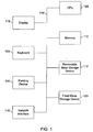
- Figure 1 is a block diagram of a computer system suitable for implementing the present invention.
- Figure 2 is an illustration of a thread transitioning through safe and unsafe regions of a computer code.
- Figure 3 is an illustration of threads progressing through a global safepoint operation according to an embodiment of the present invention.
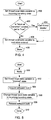
- Figure 4 is a flow diagram of a transition within a thread according to an embodiment of the present invention.
- Figure 5 is a flow diagram of a method for blocking a thread according to an embodiment of the present invention.
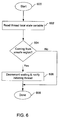
- Figure 6 is a flow diagram of a method for implementing a notify block according to an embodiment of the present invention.
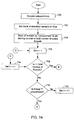
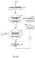
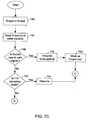
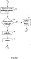
- Figure 7A - 7E are flow diagrams of a method for safepoint synchronization according to an embodiment of the present invention.
- FIG. 1 is a block diagram of a general purpose computer system 100 suitable for carrying out the processing in accordance with one embodiment of the present invention.
- Figure 1 illustrates one embodiment of a general purpose computer system.
- Computer system 100 includes at least one microprocessor subsystem (also referred to as a central processing unit, or CPU) 102. That is, CPU 102 can be implemented by a single-chip processor or by multiple processors.
- CPU 102 is a general purpose digital processor which controls the operation of the computer system 100. Using instructions retrieved from memory 110, the CPU 102 controls the reception and manipulation of input data, and the output and display of data on output devices.
- CPU 102 is coupled bi-directionally with memory 110 which can include a first primary storage, typically a random access memory (RAM), and a second primary storage area, typically a read-only memory (ROM).
- primary storage can be used as a general storage area and as scratch-pad memory, and can also be used to store input data and processed data. It can also store programming instructions and data, in the form of data objects and text objects, in addition to other data and instructions for processes operating on CPU 102.
- primary storage typically includes basic operating instructions, program code, data and objects used by the CPU 102 to perform its functions.
- Primary storage devices 110 may include any suitable computer-readable storage media, described below, depending on whether, for example, data access needs to be bi-directional or uni-directional.
- CPU 102 can also directly and very rapidly retrieve and store frequently needed data in a cache memory (not shown).
- a removable mass storage device 112 provides additional data storage capacity for the computer system 100, and is coupled either bi-directionally or uni-directionally to CPU 102.
- a specific removable mass storage device commonly known as a CD-ROM typically passes data uni-directionally to the CPU 102, whereas a floppy disk can pass data bi-directionally to the CPU 102.
- Storage 112 may also include computer-readable media such as magnetic tape, flash memory, signals embodied on a carrier wave, PC-CARDS, portable mass storage devices, holographic storage devices, and other storage devices.
- a fixed mass storage 120 can also provide additional data storage capacity. The most common example of mass storage 120 is a hard disk drive.
- Mass storage 112, 120 generally store additional programming instructions, data, and the like that typically are not in active use by the CPU 102. It will be appreciated that the information retained within mass storage 112, 120 may be incorporated, if needed, in standard fashion as part of primary storage 110 (e.g. RAM) as virtual memory.
- primary storage 110 e.g. RAM
- bus 114 can be used to provide access other subsystems and devices as well.
- these can include a display monitor 118, a network interface 116, a keyboard 104, and a pointing device 106, as well as an auxiliary input/output device interface, a sound card, speakers, and other subsystems as needed.
- the pointing device 106 may be a mouse, stylus, track ball, or tablet, and is useful for interacting with a graphical user interface.
- the network interface 116 allows CPU 102 to be coupled to another computer, computer network, or telecommunications network using a network connection as shown. Through the network interface 116, it is contemplated that the CPU 102 might receive information, e.g. , data objects or program instructions, from another network, or might output information to another network in the course of performing the above-described method steps. Information, often represented as a sequence of instructions to be executed on a CPU, may be received from and outputted to another network, for example, in the form of a computer data signal embodied in a carrier wave. An interface card or similar device and appropriate software implemented by CPU 102 can be used to connect the computer system 100 to an external network and transfer data according to standard protocols.
- method embodiments of the present invention may execute solely upon CPU 102, or may be performed across a network such as the Internet, intranet networks, or local area networks, in conjunction with a remote CPU that shares a portion of the processing.
- Additional mass storage devices may also be connected to CPU 102 through network interface 116.
- auxiliary I/O device interface (not shown) can be used in conjunction with computer system 100.
- the auxiliary I/O device interface can include general and customized interfaces that allow the CPU 102 to send and, more typically, receive data from other devices such as microphones, touch-sensitive displays, transducer card readers, tape readers, voice or handwriting recognizers, biometrics readers, cameras, portable mass storage devices, and other computers.
- embodiments of the present invention further relate to computer storage products with a computer readable medium that contain program code for performing various computer-implemented operations.
- the computer-readable medium is any data storage device that can store data which can thereafter be read by a computer system.
- the media and program code may be those specially designed and constructed for the purposes of the present invention, or they may be of the kind well known to those of ordinary skill in the computer software arts.
- Examples of computer-readable media include, but are not limited to, all the media mentioned above: magnetic media such as hard disks, floppy disks, and magnetic tape; optical media such as CD-ROM disks; magneto-optical media such as floptical disks; and specially configured hardware devices such as application-specific integrated circuits (ASICs), programmable logic devices (PLDs), and ROM and RAM devices.
- the computer-readable medium can also be distributed as a data signal embodied in a carrier wave over a network of coupled computer systems so that the computer-readable code is stored and executed in a distributed fashion.
- Examples of program code include both machine code, as produced, for example, by a compiler, or files containing higher level code that may be executed using an interpreter.
- the computer system shown in Fig. 1 is but an example of a computer system suitable for use with the invention.
- Other computer systems suitable for use with the invention may include additional or fewer subsystems.
- bus 114 is illustrative of any interconnection scheme serving to link the subsystems.
- Other computer architectures having different configurations of subsystems may also be utilized.
- the present invention is a system and method for facilitating a global safepoint operation in a multithreaded computer system.
- each thread keeps track of its safepoint regions by maintaining a variable which indicates a state, such as whether the current region of the thread is safe, unsafe, or transitional. In this manner, it can be determined whether a thread is currently in a safepoint region without suspending the thread.
- a thread is currently in a safepoint region, the thread can continue to operate while a global safepoint operation, such as garbage-collection is being performed.
- garbage-collection is being performed.
- the thread begins to transition out of the safe region, it moves into a transitional region. The transitional region automatically blocks the transition into the non-safe region to assure that the safepoint operation occurs in a safe region.
- one thread may begin a safepoint procedure after it acquires a safepoint lock.
- the safepoint lock blocks other threads from attempting to perform the safepoint procedure at the same time. Prior to initiating a safepoint operation, the thread attempting to initiate the safepoint operation will wait until all other threads reach a safe region in each of their own code.
- Figure 2 is an illustration of a thread transitioning between safe and unsafe regions of a computer code.
- Figure 2 shows thread 200 transitioning from a safe region 202A to an unsafe region 204 via a transition region 206A.
- the transition region 206A is a transition from a safe region to an unsafe region.
- the thread 200 is also shown to transition from the unsafe region 204 to a safe region 202B via a transition region 206B, wherein the transition region 206B is a transition from an unsafe region to a safe region.
- a global safepoint operation such as garbage collection, may proceed while thread 200 continues to operate.
- thread 200 may be blocked from continuing into the unsafe region 204 to insure that thread 200 stays in a safe region during the global safepoint operation.
- unsafe regions are regions of code through which a thread is passing wherein pointers may be manipulated. Examples of unsafe regions include virtual machine code, JavaTM code, and code which is unidentified.
- the JavaTM code may include compiler code and interpretive code.
- Figure 3 is an illustration of a set of threads progressing through a global safepoint operation according to an embodiment of the present invention.
- Figure 3 shows a set of threads 200A-200E, each progressing through their own set of computer codes.
- Points 304A and 304B represent state transitions for each thread 200A-200E.
- point 304A for thread 200A may be a transition from a safe region to an unsafe region
- point 304A for thread 200B may be a transition from an unsafe region to a safe region.
- point 304B for thread 200D may be a transition from an unsafe region to a safe region
- point 304B for thread 200E may be a transition from a safe region to an unsafe region.
- the global safepoint operation is expected to be programmed such that it is code which is considered to be a safe region. Accordingly, when thread 200C initiates begin safepoint 300, it is assumed that thread 200C is moving through a safe region of code. Thus, thread 200C's state flag should not need to be checked.
- Thread 200C then acquires a safepoint lock at begin safepoint 300. Since thread 200C is the thread which initiates the safepoint operation, it is often herein referred to as the initiating thread.
- the safepoint lock ensures that thread 200C is the only thread allowed to perform the global safepoint operation, thus avoiding simultaneous attempts at performing global safepoint operations by different threads. Additionally, since the remaining threads 200A-200B, 200D-200E cannot acquire the safepoint lock, an attempt to acquire the safepoint lock by the remaining threads 200A-200B, 200D-200E will block further progress by these threads. Accordingly, when the remaining threads 200A-200B, 200D-200E move into a transition region from a safe region, they may be blocked from progressing further into an unsafe region by causing these threads to attempt to acquire the safepoint lock.
- thread 200C After acquiring the safepoint lock, thread 200C then waits until every other thread 200A, 200B, 200D, 200E, has reached a safe region within their code.
- a remaining thread 200A-200B, 200D-200E transitions from an unsafe region (such as region 204 of Figure 2) to a safe region (such as region 202B of Figure 2)
- a waiting counter is decremented to indicate that this thread is one less thread for thread 200C to wait upon.
- a waiting counter is decremented to indicate that this thread is one less thread for thread 200C to wait upon.
- the remaining threads 200A, 200B, 200D, 200E are in safe regions, they continue to progress until each of those threads runs into a transition region from a safe region to an unsafe region. When a thread moves into such a transition, it is blocked to keep it from progressing out of the safe region and into an unsafe region.
- the global safepoint operation such as garbage collection, may be initiated.
- thread 200A transitions into a safe region. Then thread 200A may continue to operate after begin safepoint 300 until it reaches a transition state 304C.
- begin safepoint 300 thread 200A's state flag will be checked to determine the type of region thread 200A is moving through. In this example, thread 200A's state flag will indicate that it is in a safe region.
- transition state 304C thread 200A will be blocked to ensure that it does not move into an unsafe region during the global safepoint operation.
- thread 200B transitions into an unsafe region at point 304B.
- begin safepoint 300 thread 200B's state flag is checked to determine what type of region thread 200B is moving through. In this example, thread 200B' state flag will indicate that it is in an unsafe region. Thread 200B is then suspended and handled such that a safepoint operation may be performed. Further details of unsafe region handling will later be discussed in conjunction with Figures 7B-7D.
- thread 200D is in a transition from a safe region to an unsafe region at the time thread 200D's state flag is checked after begin safepoint 300 is initiated. Then the progress of thread 200D is blocked to keep thread 200D from moving into an unsafe region. If thread 200E is in a transition from an unsafe region to a safe region at the time thread 200D's state flag is checked (after begin safepoint 300 is initiated), then thread 200E is allowed to continue its progress. If thread 200E reaches another transition state indicating a transition into an unsafe region, then it is blocked at point 304E.
- the safepoint operation may be initiated at point 350.
- the global safepoint operation is complete at point 352
- a variable is set such that threads 200A-200E are no longer blocked at transitions, the safepoint lock is released by the initiating thread 200C, and any threads which have been suspended are then unsuspended.
- the safepoint procedure is ended at point 302.
- Figures 4-6 describe events which occur for each thread at checkpoints 304A - 304D of Figure 3, while Figures 7A-7E describe events which occur at begin and end safepoints 300 and 302 of Figure 3.
- Figure 4 is a flow diagram of a transition between program code regions within a thread according to an embodiment of the present invention.
- a thread local state variable is set to an incoming transitory state in step 400.
- the thread local state variable may be a flag indicating the state of the region through which the thread is passing. For example, if a thread was transitioning from a safe region to an unsafe region, the transition region may be indicated by a number which sets the thread local state variable to indicate that it is a transition from a safe region to an unsafe region. Examples of other states which may be indicated by the thread local state variable include safe region, unsafe region, transition from a safe region to an unsafe region, and a transition from an unsafe region to a safe region.
- block at transition variable
- the "block at transition” variable indicates whether a thread should be blocked at a transition region.
- a thread block is simpler and easier to perform than a thread suspend.
- a thread When a thread is blocked, it simply does not proceed on to the next state or region, whereas when threads are suspended, the operating system typically must perform the suspend operation. Accordingly, it is simpler and less expensive to block a thread than to suspend the thread .
- step 402 If "block at transition” variable is set to true in step 402, then a thread blocker is called in step 404. Details of the thread blocker will be discussed later in conjunction with figure 5. Thereafter, the thread local state variable is set to the next state which is entered by the thread in step 406.
- step 402 thread local state variable is set to the next state (region) entered by the thread in step 406, and the transition is completed in step 408.
- Figure 5 is a flow diagram of a method for blocking a thread according to an embodiment of the present invention. The flow diagram of Figure 5 occurs when the thread blocker is called in step 404 of Figure 4.
- a notify block is implemented in step 500. Details of the implementation of the notify block will later be discussed in conjunction with Figure 6.
- the thread local state variable is then set to a "blocked” state in step 502.
- a safepoint lock is then acquired in step 504. If the safepoint lock may not be immediately acquired (because the initiating thread has already acquired it), then it waits until the safepoint lock may be acquired. Waiting to acquire the safepoint lock keeps the thread in a "blocked” state by holding its position until the safepoint lock is acquired. The "blocked" state indicates to the initiating thread that this thread is in a safe region. The safepoint lock may only be acquired after the thread holding the safepoint lock releases it. Since the thread holding the safepoint lock will not release the safepoint lock until the global safepoint operation is completed, this thread is blocked throughout the global safepoint operation by waiting to acquire the safepoint lock.
- the acquisition of a safepoint lock allows the initiating thread, such as thread 200C of Figure 3, to progress beyond the begin safepoint 300 and have the desired safepoint operation executed upon it, without the other threads 200A, 200B, 200D, and 200E accessing and interfering with the safepoint operation.
- the thread local state variable of this thread is then changed to the incoming transitory state in step 506.
- the safepoint lock is acquired by each thread, one at a time, and each thread is allowed to move forward (transition into the next state).
- the safepoint lock is then released in step 508, and the thread blocker is completed in step 510.
- FIG. 6 is a flow diagram of the implementation of the notify block, such as the implementation of the notify block of step 500 of Figure 5.
- the notify block begins at step 600, and thread local state variable is read in step 602. It is then determined whether this thread is transitioning from an unsafe region in step 604. If the thread is not coming from an unsafe region, then the notify block is finished in step 608. If, however, the thread is coming from an unsafe region in step 604, then a waiting counter is decremented to notify the initiating thread that it need no longer wait for this particular thread to enter a safe region in step 606. Thereafter, the notify block is completed in step 608.
- Figures 7A-7E are flow diagrams of safepoint synchronization according to an embodiment of the present invention.
- Figures 7A-7E represent events which occur during and between begin safepoint 300 and end safepoint 302 of Figure 3.
- a safepoint lock is acquired in step 700.
- a " block at transition” variable is set to true in step 702. All threads are marked as “ unexamined” and a waiting counter is set to equal the total number of active threads in step 704.
- a variable “i” is set equal to 1 in step 706, wherein “i” indicates a particular thread. It is then determined whether “i” equals the total number of threads in step 708. If “i” does equal the total number of threads in step 708, then the flow diagram shown on Figure 7E is referenced.
- step 708 If, however, "i" does not equal the total number of threads in step 708, then it is determined whether thread "i" is unexamined in step 710. If thread "i" is not unexamined in step 710, then “i” is set equal to "i" + 1 in step 712. Thereafter, it is again determined whether “i” equals the total number of threads in step 708.
- Figure 7C is a flow diagram of a method for handling unsafe regions, such as step 730 of Figure 7B, according to an embodiment of the present invention.
- the thread that is in an unsafe region is suspended in step 742.
- the thread local state variable of thread "i" is then read in step 744.
- the thread local state variable is checked again in step 744, and it is again determined if the thread is now in a safe region in step 746. If the thread is now in a safe region in step 746, then the thread is resumed (unsuspended) in step 748.
- the thread is then marked as "examined” in step 750. Thereafter, Figure 7A is again referenced at point C, and "i" is set equal to "i" + 1 in step 714.
- thread “i” is still not in a safe region in step 746, then it is determined whether thread “i” is in a transitory state in step 752. If it is determined that thread “i” is in an transitory state in step 752, then thread “i” is resumed (unsuspended) in step 754. Thread “i” is not marked as “examined” and is later reexamined to determine if it is in a safe region. Thereafter, Figure 7A is again referenced at point C, and "i" is set equal to "i” + 1 in step 714.
- FIG. 7D an application specific analysis of the location of the thread is performed in step 760.
- the application specific analysis is user (programmer) configurable, depending on the application code through which the thread is running. In the example shown in Figure 7D, it is assumed that the application through which the thread is running is an unsafe region of interpretive code. For the example of the interpretive code, the application specific analysis may be that although the thread is running through an unsafe region, the thread may be allowed to continue to run since it may be assumed that the interpretive code will contain call backs to safe regions.
- step 762 It is then determined whether to wait for the thread to reach the next transition in step 762. This determination may be made depending on the application specific analysis. For example, if the unsafe region is in a region of interpretive code, then according to our example, the determination would be made to wait for the thread to reach the next transition.
- an application specific handling is performed in step 764.
- An example of application specific handling includes a situation where there are microsafe regions within an unsafe region. Microsafe regions are pockets of safe regions within an unsafe region. Microsafe regions indicate finer grained transitions than that which might be applied to other regions. These microsafe regions may have explicit checks indicating transitions (transitional regions). For example, if the unsafe region is in compile code, then the user (programmer) may prefer to use microtransitions to indicate microsafe regions within an unsafe region. If the thread is in a microsafe region within the compile code, then user (programmer) preference may be to roll ahead a few instructions until the thread reaches a microsafe region. Once a microsafe region is reached, this thread may be safe for a global safepoint operation.
- step 762 If it is determined to wait for the thread to reach the next transition in step 762, then set thread "i" to "examined” in step 766. Thereafter, the progress of the thread is resumed (unsuspended) in step 768.
- Figure 7A is then again referenced at point C, and "i" is set equal to "i" + 1 and the next thread is examined. Note that the waiting counter was not decremented for this case where this thread was found to be in an unsafe region. When the thread reaches a transition from an unsafe region to a safe region, then the waiting counter will be decremented and the initiating thread will be notified, such as in step 606 of Figure 6.
- Figure 7E is referenced when it is determined that "i" equals the total number of threads in step 708 of Figure 7A. If “i” equals the total number of threads in step 708, then it is determined whether any unexamined threads remain in step 770. If any unexamined threads remain, then Figure 7A is referenced at point D, and " i" is set equal to zero in step 706.
- step 770 If there are no unexamined threads remaining in step 770, then it is determined whether the waiting counter is greater than zero in step 772. If the waiting counter is greater than zero in step 772, then there is a wait for the waiting counter to decrement in step 774. As previously mentioned in conjunction with Figure 3 and Figure 6, the waiting counter decrements when any of the threads moves through a transition region indicating a transition from an unsafe region to a safe region. After the waiting counter decrements, it is again determined whether the waiting counter is greater than the zero in step 772.
- the desired global safepoint operation such as garbage collection, may be executed in step 776.
- the "block at transition" variable is then set to false to permit threads to move beyond transition regions and into unsafe regions in step 778.
- the safepoint lock is also released to permit another thread to obtain the safepoint lock in step 780.
- any suspended threads are resumed (unsuspended) if there were any suspended threads in step 782.
- the process is completed.
- a method and system for facilitating safepoint synchronization in a multi-threaded computer system environment has been disclosed.
- Software written according to the present invention may be stored in some form of computer-readable medium, such as memory or CD-ROM, or transmitted over a network, and executed by a processor.
Landscapes
- Engineering & Computer Science (AREA)
- Software Systems (AREA)
- Theoretical Computer Science (AREA)
- Physics & Mathematics (AREA)
- General Engineering & Computer Science (AREA)
- General Physics & Mathematics (AREA)
- Debugging And Monitoring (AREA)
- Safety Devices In Control Systems (AREA)
Applications Claiming Priority (2)
| Application Number | Priority Date | Filing Date | Title |
|---|---|---|---|
| US09/206,810 US6523059B1 (en) | 1998-12-07 | 1998-12-07 | System and method for facilitating safepoint synchronization in a multithreaded computer system |
| US206810 | 1998-12-07 |
Publications (3)
| Publication Number | Publication Date |
|---|---|
| EP1014264A2 true EP1014264A2 (fr) | 2000-06-28 |
| EP1014264A3 EP1014264A3 (fr) | 2003-07-02 |
| EP1014264B1 EP1014264B1 (fr) | 2007-04-18 |
Family
ID=22768071
Family Applications (1)
| Application Number | Title | Priority Date | Filing Date |
|---|---|---|---|
| EP99309854A Expired - Lifetime EP1014264B1 (fr) | 1998-12-07 | 1999-12-07 | Système et méthode pour faciliter la synchronisation à des points sûrs dans un système d'ordinateur à plusieurs fils d'exécution |
Country Status (2)
| Country | Link |
|---|---|
| US (1) | US6523059B1 (fr) |
| EP (1) | EP1014264B1 (fr) |
Cited By (2)
| Publication number | Priority date | Publication date | Assignee | Title |
|---|---|---|---|---|
| WO2001097018A3 (fr) * | 2000-06-12 | 2003-04-03 | Sun Microsystems Inc | Procede et appareil permettant a des unites d'execution d'atteindre un etat coherent sans suspension d'unite d'execution explicite |
| US7937685B2 (en) | 2005-01-13 | 2011-05-03 | Hsbc Technology & Services (Usa) Inc. | Computer software implemented framework for configuration and release management of group systems software, and method for same |
Families Citing this family (16)
| Publication number | Priority date | Publication date | Assignee | Title |
|---|---|---|---|---|
| JP3630118B2 (ja) * | 2001-07-12 | 2005-03-16 | 日本電気株式会社 | スレッド終了方法及び装置並びに並列プロセッサシステム |
| US6728738B2 (en) * | 2002-04-03 | 2004-04-27 | Sun Microsystems, Inc. | Fast lifetime analysis of objects in a garbage-collected system |
| US7080374B2 (en) * | 2002-12-18 | 2006-07-18 | Bea Systems, Inc. | System and method for using native code interpretation to move threads to a safe state in a run-time environment |
| US7337444B2 (en) * | 2003-01-09 | 2008-02-26 | International Business Machines Corporation | Method and apparatus for thread-safe handlers for checkpoints and restarts |
| US7552302B1 (en) * | 2004-09-14 | 2009-06-23 | Azul Systems, Inc. | Ordering operation |
| US7765555B2 (en) * | 2005-06-17 | 2010-07-27 | Oracle America, Inc. | Facilitating bulk lock-unbiasing in an object-based system |
| US7519967B1 (en) | 2005-06-17 | 2009-04-14 | Sun Microsystems, Inc. | Facilitating biased synchronization in an object-based system |
| US7418630B1 (en) * | 2005-06-27 | 2008-08-26 | Sun Microsystems, Inc. | Method and apparatus for computer system diagnostics using safepoints |
| US7516361B2 (en) * | 2005-06-27 | 2009-04-07 | Sun Microsystems, Inc. | Method for automatic checkpoint of system and application software |
| US7945913B2 (en) * | 2006-01-19 | 2011-05-17 | International Business Machines Corporation | Method, system and computer program product for optimizing allocation of resources on partitions of a data processing system |
| US8782434B1 (en) | 2010-07-15 | 2014-07-15 | The Research Foundation For The State University Of New York | System and method for validating program execution at run-time |
| US9063721B2 (en) | 2012-09-14 | 2015-06-23 | The Research Foundation For The State University Of New York | Continuous run-time validation of program execution: a practical approach |
| US9069782B2 (en) | 2012-10-01 | 2015-06-30 | The Research Foundation For The State University Of New York | System and method for security and privacy aware virtual machine checkpointing |
| US9880931B2 (en) * | 2015-10-15 | 2018-01-30 | Oracle International Corporation | Safepoints for guest languages on a virtual machine |
| US11392570B2 (en) * | 2018-03-09 | 2022-07-19 | Microsoft Technology Licensing, Llc | Key-value store system |
| US10776161B2 (en) | 2018-11-30 | 2020-09-15 | Oracle International Corporation | Application code callbacks at regular intervals |
Family Cites Families (4)
| Publication number | Priority date | Publication date | Assignee | Title |
|---|---|---|---|---|
| US5630136A (en) * | 1995-06-09 | 1997-05-13 | Sun Microsystems, Inc. | Method and apparatus for serializing access to multithreading unsafe resources |
| US6167423A (en) * | 1997-04-03 | 2000-12-26 | Microsoft Corporation | Concurrency control of state machines in a computer system using cliques |
| US5842016A (en) * | 1997-05-29 | 1998-11-24 | Microsoft Corporation | Thread synchronization in a garbage-collected system using execution barriers |
| US6026428A (en) * | 1997-08-13 | 2000-02-15 | International Business Machines Corporation | Object oriented thread context manager, method and computer program product for object oriented thread context management |
-
1998
- 1998-12-07 US US09/206,810 patent/US6523059B1/en not_active Expired - Lifetime
-
1999
- 1999-12-07 EP EP99309854A patent/EP1014264B1/fr not_active Expired - Lifetime
Cited By (3)
| Publication number | Priority date | Publication date | Assignee | Title |
|---|---|---|---|---|
| WO2001097018A3 (fr) * | 2000-06-12 | 2003-04-03 | Sun Microsystems Inc | Procede et appareil permettant a des unites d'execution d'atteindre un etat coherent sans suspension d'unite d'execution explicite |
| US7086053B2 (en) | 2000-06-12 | 2006-08-01 | Sun Microsystems, Inc. | Method and apparatus for enabling threads to reach a consistent state without explicit thread suspension |
| US7937685B2 (en) | 2005-01-13 | 2011-05-03 | Hsbc Technology & Services (Usa) Inc. | Computer software implemented framework for configuration and release management of group systems software, and method for same |
Also Published As
| Publication number | Publication date |
|---|---|
| US6523059B1 (en) | 2003-02-18 |
| EP1014264B1 (fr) | 2007-04-18 |
| EP1014264A3 (fr) | 2003-07-02 |
Similar Documents
| Publication | Publication Date | Title |
|---|---|---|
| EP1014264B1 (fr) | Système et méthode pour faciliter la synchronisation à des points sûrs dans un système d'ordinateur à plusieurs fils d'exécution | |
| US5093912A (en) | Dynamic resource pool expansion and contraction in multiprocessing environments | |
| EP0969383A2 (fr) | Méthode pour la gestion efficace de mémoire principale non-virtuelle | |
| EP0247374B1 (fr) | Ressources de mémoire virtuelle pour un programme de commande d'un système d'exploitation | |
| US7086053B2 (en) | Method and apparatus for enabling threads to reach a consistent state without explicit thread suspension | |
| EP1049979B1 (fr) | Recuperation incrementielle de positions inutilisees | |
| KR100488288B1 (ko) | 목적-베이스시스템내쓰레드동기화를위한방법및장치 | |
| US6874074B1 (en) | System and method for memory reclamation | |
| EP1978444A1 (fr) | Appareil et procédé de collecte de ressources devenues inutiles | |
| US8291426B2 (en) | Memory allocators corresponding to processor resources | |
| JP2000222281A (ja) | マルチスレッド仮想マシン内におけるメモリ・アロケ―ションの方法及び装置 | |
| JPH10254756A (ja) | リファレンスされたオブジェクトを管理するための3状態リファレンスの使用 | |
| JP2003531434A (ja) | Javaコンピュータプログラムを実行するためのコンピュータ方法およびシステム | |
| US10423467B2 (en) | Data processing apparatus and method for performing lock-protected processing operations for multiple threads | |
| KR101885030B1 (ko) | 하이브리드 트랜잭셔널 메모리 시스템에서의 트랜잭션 처리 방법 및 트랜잭션 처리 장치 | |
| CA1160351A (fr) | Terminal a memoire virtuelle | |
| EP1020801A2 (fr) | Allocation dynamique d'intervalles de temps et suivi des demandes de mémoire multiples | |
| JPH07129518A (ja) | 計算機システム | |
| US20060230242A1 (en) | Memory for multi-threaded applications on architectures with multiple locality domains | |
| EP0216170A2 (fr) | Méthode et système de gestion de mémoire dans un environnement multiprocesseur | |
| JP2003248620A (ja) | 動的メモリ管理方法及び動的メモリ管理情報処理装置 | |
| CN119271412B (zh) | 一种麒麟V10系统中percpu内存占用的优化方法 | |
| JPS603229B2 (ja) | 情報処理方式 | |
| JP3061001B2 (ja) | 計算機システムにおけるメモリ割り当て方式 | |
| JPH06187312A (ja) | マルチcpuシステムにおける処理方法および装置 |
Legal Events
| Date | Code | Title | Description |
|---|---|---|---|
| PUAI | Public reference made under article 153(3) epc to a published international application that has entered the european phase |
Free format text: ORIGINAL CODE: 0009012 |
|
| AK | Designated contracting states |
Kind code of ref document: A2 Designated state(s): AT BE CH CY DE DK ES FI FR GB GR IE IT LI LU MC NL PT SE |
|
| AX | Request for extension of the european patent |
Free format text: AL;LT;LV;MK;RO;SI |
|
| PUAL | Search report despatched |
Free format text: ORIGINAL CODE: 0009013 |
|
| AK | Designated contracting states |
Designated state(s): AT BE CH CY DE DK ES FI FR GB GR IE IT LI LU MC NL PT SE |
|
| AX | Request for extension of the european patent |
Extension state: AL LT LV MK RO SI |
|
| 17P | Request for examination filed |
Effective date: 20031212 |
|
| AKX | Designation fees paid |
Designated state(s): GB |
|
| REG | Reference to a national code |
Ref country code: DE Ref legal event code: 8566 |
|
| 17Q | First examination report despatched |
Effective date: 20040512 |
|
| 17Q | First examination report despatched |
Effective date: 20040512 |
|
| GRAP | Despatch of communication of intention to grant a patent |
Free format text: ORIGINAL CODE: EPIDOSNIGR1 |
|
| GRAS | Grant fee paid |
Free format text: ORIGINAL CODE: EPIDOSNIGR3 |
|
| GRAA | (expected) grant |
Free format text: ORIGINAL CODE: 0009210 |
|
| AK | Designated contracting states |
Kind code of ref document: B1 Designated state(s): GB |
|
| PLBE | No opposition filed within time limit |
Free format text: ORIGINAL CODE: 0009261 |
|
| STAA | Information on the status of an ep patent application or granted ep patent |
Free format text: STATUS: NO OPPOSITION FILED WITHIN TIME LIMIT |
|
| 26N | No opposition filed |
Effective date: 20080121 |
|
| GBPC | Gb: european patent ceased through non-payment of renewal fee |
Effective date: 20071207 |
|
| PG25 | Lapsed in a contracting state [announced via postgrant information from national office to epo] |
Ref country code: GB Free format text: LAPSE BECAUSE OF NON-PAYMENT OF DUE FEES Effective date: 20071207 |