EP1014506A2 - Connecteur enfichable zero force d'insertion destine a module à broches en grille - Google Patents
Connecteur enfichable zero force d'insertion destine a module à broches en grille Download PDFInfo
- Publication number
- EP1014506A2 EP1014506A2 EP99124290A EP99124290A EP1014506A2 EP 1014506 A2 EP1014506 A2 EP 1014506A2 EP 99124290 A EP99124290 A EP 99124290A EP 99124290 A EP99124290 A EP 99124290A EP 1014506 A2 EP1014506 A2 EP 1014506A2
- Authority
- EP
- European Patent Office
- Prior art keywords
- cover
- base housing
- actuator
- electrical connector
- metal component
- Prior art date
- Legal status (The legal status is an assumption and is not a legal conclusion. Google has not performed a legal analysis and makes no representation as to the accuracy of the status listed.)
- Withdrawn
Links
- 238000003780 insertion Methods 0.000 title claims abstract description 42
- 230000037431 insertion Effects 0.000 title claims abstract description 38
- 239000002184 metal Substances 0.000 claims description 82
- 239000000463 material Substances 0.000 claims description 15
- 239000003351 stiffener Substances 0.000 description 26
- 239000004033 plastic Substances 0.000 description 11
- 239000012634 fragment Substances 0.000 description 10
- 230000014759 maintenance of location Effects 0.000 description 9
- 239000011347 resin Substances 0.000 description 9
- 229920005989 resin Polymers 0.000 description 9
- 229910000679 solder Inorganic materials 0.000 description 7
- 230000002787 reinforcement Effects 0.000 description 3
- 239000006185 dispersion Substances 0.000 description 2
- 238000000465 moulding Methods 0.000 description 2
- XUIMIQQOPSSXEZ-UHFFFAOYSA-N Silicon Chemical compound [Si] XUIMIQQOPSSXEZ-UHFFFAOYSA-N 0.000 description 1
- 238000007792 addition Methods 0.000 description 1
- 230000000295 complement effect Effects 0.000 description 1
- 239000011810 insulating material Substances 0.000 description 1
- 238000004519 manufacturing process Methods 0.000 description 1
- 239000007769 metal material Substances 0.000 description 1
- 238000000034 method Methods 0.000 description 1
- 239000002991 molded plastic Substances 0.000 description 1
- 230000000630 rising effect Effects 0.000 description 1
- 229910052710 silicon Inorganic materials 0.000 description 1
- 239000010703 silicon Substances 0.000 description 1
- 238000005476 soldering Methods 0.000 description 1
Images





Classifications
-
- H—ELECTRICITY
- H01—ELECTRIC ELEMENTS
- H01R—ELECTRICALLY-CONDUCTIVE CONNECTIONS; STRUCTURAL ASSOCIATIONS OF A PLURALITY OF MUTUALLY-INSULATED ELECTRICAL CONNECTING ELEMENTS; COUPLING DEVICES; CURRENT COLLECTORS
- H01R33/00—Coupling devices specially adapted for supporting apparatus and having one part acting as a holder providing support and electrical connection via a counterpart which is structurally associated with the apparatus, e.g. lamp holders; Separate parts thereof
- H01R33/74—Devices having four or more poles, e.g. holders for compact fluorescent lamps
- H01R33/76—Holders with sockets, clips, or analogous contacts adapted for axially-sliding engagement with parallely-arranged pins, blades, or analogous contacts on counterpart, e.g. electronic tube socket
-
- H—ELECTRICITY
- H01—ELECTRIC ELEMENTS
- H01R—ELECTRICALLY-CONDUCTIVE CONNECTIONS; STRUCTURAL ASSOCIATIONS OF A PLURALITY OF MUTUALLY-INSULATED ELECTRICAL CONNECTING ELEMENTS; COUPLING DEVICES; CURRENT COLLECTORS
- H01R12/00—Structural associations of a plurality of mutually-insulated electrical connecting elements, specially adapted for printed circuits, e.g. printed circuit boards [PCB], flat or ribbon cables, or like generally planar structures, e.g. terminal strips, terminal blocks; Coupling devices specially adapted for printed circuits, flat or ribbon cables, or like generally planar structures; Terminals specially adapted for contact with, or insertion into, printed circuits, flat or ribbon cables, or like generally planar structures
- H01R12/70—Coupling devices
- H01R12/82—Coupling devices connected with low or zero insertion force
- H01R12/85—Coupling devices connected with low or zero insertion force contact pressure producing means, contacts activated after insertion of printed circuits or like structures
- H01R12/88—Coupling devices connected with low or zero insertion force contact pressure producing means, contacts activated after insertion of printed circuits or like structures acting manually by rotating or pivoting connector housing parts
-
- H—ELECTRICITY
- H05—ELECTRIC TECHNIQUES NOT OTHERWISE PROVIDED FOR
- H05K—PRINTED CIRCUITS; CASINGS OR CONSTRUCTIONAL DETAILS OF ELECTRIC APPARATUS; MANUFACTURE OF ASSEMBLAGES OF ELECTRICAL COMPONENTS
- H05K7/00—Constructional details common to different types of electric apparatus
- H05K7/02—Arrangements of circuit components or wiring on supporting structure
- H05K7/10—Plug-in assemblages of components, e.g. IC sockets
- H05K7/1007—Plug-in assemblages of components, e.g. IC sockets with means for increasing contact pressure at the end of engagement of coupling parts
Definitions
- the present invention relates generally to an electrical connector and, more particularly, to a socket and actuator for connecting a pin grid-array ("PGA") package to a circuit member.
- PGA pin grid-array
- a typical PGA package includes a silicon chip, a package including conductive and non-conductive components and a plurality of pins in a grid array depending downward from a bottom surface of the package.
- sockets for PGA packages include a plate-like base housing having a plurality of terminals arranged in the same grid pattern as the lead pins of the PGA package and a plate-like cover member having a plurality of through holes in the same grid pattern as the lead pins of the pin grid-array package, thus permitting the lead pins to be inserted in the through holes.
- the plate-like cover member is slidably positioned on the upper surface of the base housing.
- the base housing and cover are slidably interconnected so that the cover is driven in a plane parallel to the underlying base housing between a first position in which the lead pins of the PGA package can pass through the through holes of the cover to reach the terminals mounted in the underlying base housing without requiring any insertion force to be applied to the lead pins and a second position in which the lead pins of the PGA package contact the terminals.
- terminal structures have been proposed as appropriate for use in such sockets.
- Some such terminals are configured such that their contact portions engage the lead pins of a PGA package upon movement of the cover of the socket, as shown in Japanese Patent Application Laid-Open No. 7-142134 and Japanese Registered Utility Model No. 2-536440 referred to above.
- some terminals are configured such that the lead pins of a PGA package are brought to the contact portions of terminals in the base housing as shown in Japanese Patent Application Laid-Open No. 9-185981.
- terminals Essentially all of the terminals have contact portions located in the terminal-receiving cavities of the base housing of the socket, and most have straight pin-like solder tails extending from the bottom of the base housing of the socket. These pin-like solder tails are inserted into through holes of a printed circuit board on which the socket is mounted, and are soldered to the printed circuit board.
- the base housing typically has some type of drive mechanism formed thereon for slidably moving the cover over the underlying base housing.
- a cam is rotatably attached to one lateral side or end of the base housing, and the cam is adapted to be rotated with an associated handle, thereby permitting the cam axle to push or pull the cover over the underlying base housing.
- the handle may be rotated from a horizontal position in which it is parallel to the base housing to a vertical position in which it is perpendicular to the base housing.
- one object of the present invention is to provide a small-sized socket structure for a pin grid-array package.
- the electrical connector includes a base housing and a cover.
- the base housing has an upper surface and a lower surface and a plurality of terminal-receiving cavities arranged in a terminal-receiving cavity array generally corresponding to the pin terminal array.
- the cover is mounted on the upper surface of the base housing and is movable relative to the base housing between a first pin insertion position and a second pin engagement position.
- One of the cover and the base housing may have a metal component adjacent an end thereof.
- the metal component has an opening for receiving an actuator therein and a metal component stop member adjacent the opening.
- a plurality of conductive terminals are provided with one of the terminals being mounted in each cavity.
- a rotatable actuator is also provided and is operable to slide the cover relative to the base housing between the first insertion position and the second engagement position.
- the actuator has an actuator stop member configured to engage the metal component stop member upon rotation of the actuator in order to prevent rotation of the actuator past a predetermined angular position and thus limit linear motion of the cover relative to the base housing.
- the base housing may include a metal component extending along one end of the base housing and being spaced from the terminal-receiving cavities.
- Such metal component includes an opening therein configured for engagement by the actuator.
- the metal component may further include arms extending along opposite sides of the base housing with the arms spaced from the terminal-receiving cavities.
- the cover may include guide structure that interacts with edges of the base member to guide the cover between the first insertion position and the second engagement position.
- the cover may include a generally planar layer of sheet metal and a generally planar layer of insulative material.
- the cover may also include a second metal component which extends along one end of the cover and is spaced from the through holes.
- This metal component could include a cam follower surface configured to engage the socket actuator.
- the actuator may be a metal component.
- the metal component stop member may be a projection on the cover adjacent the opening and the projection may extend into the opening.
- Another object of the present invention is to provide a socket similar to that described above but wherein the socket does not include a metal component with an opening therein.
- the actuator has an axis of rotation generally perpendicular to the plane of the cover and further includes an actuator stop member configured to engage the stop projection upon rotation of the actuator in order to prevent rotation of the actuator past a predetermined angular position and thus limit linear motion of the cover relative to the base housing.
- Another object of the present invention is to provide still another socket similar to that described above and wherein the one of the cover and base housing further include a mounting region for receiving an actuator thereat.
- the actuator and the mounting region include orientation structure to prevent the actuator from being inserted into the mounting region when the actuator is oriented at certain predetermined angular orientations.
- Still another object of the present invention is to provide a socket similar to that described above but wherein the actuator and mounting region include securing structure to secure the actuator to one of the cover and base housing within the mounting region without any additional components.
- the actuator may include at least one projection to secure the actuator to the base housing.
- a socket 50 for a PGA package comprises a plate-like base housing 51 and an overlying plate-like slide member or cover 52.
- the plate-like cover 52 slidably moves in a plane parallel to the plane of the underlying plate-like base housing 51.
- the base housing 51 and cover 52 have semicircular extensions 51a and 52a formed on respective lateral sides or ends thereof with holes therein for receiving an eccentric cam member or actuator 53 to provide drive means for driving the cover 52 linearly along base housing 51.
- the eccentric cam member 53 is as tall as the total thickness of the base housing 51 and cover 52, so that the upper and lower surfaces of the cam 53 are flush with the upper surface of the cover 52 and the lower surface of the base housing 51, respectively.
- the cover 52 has L-shaped guide pieces 54 integrally formed on its opposite longitudinal sides for guiding the movement of cover 52 in the direction indicated by double-headed arrow 55.
- the cover 52 has a plurality of through holes 56 arranged in the same grid pattern as the lead pins 118 of the PGA package 117 (Figs. 45 and 46) which socket 50 is designed to receive, thus permitting the lead pins to be inserted in the through holes 56.
- the underlying base housing 51 has terminal-receiving cavities provided in a one-to-one corresponding relationship with the through holes 56 of the overlying cover 52. Each terminal-receiving cavity has a terminal 57 press-fit therein. As discussed in greater detail below, the terminals 57 are configured to engage the lead pins 118 of PGA package 117 when it is mounted on the socket and the cover 52 is in its contact engagement position.
- Fig. 2 is a somewhat schematic exploded perspective view of socket 50, and is illustrated in this manner for the sake of facilitating the understanding of the structure thereof.
- the plastic components 59 and 64 of base housing 51 and cover 52, respectively, are not separate components that are assembled with other components to form the base housing and cover. Instead, they are plastic components that are molded around metal components of the base housing and cover. Thus, the plastic portions of the base housing 51 and cover 52 never exist as the separate components shown in Figure 2.
- the base housing 51 is a generally rectangular or square molded plate of insulating plastic or resin material 59 which has a metal frame 58 as its core.
- the square molded plate has terminal-receiving holes or cavities 60 arranged in the form of a lattice. Each cavity has a terminal 57 press-fit therein from its bottom side.
- the slide cover 52 is a generally rectangular or square molded plate of insulating plastic or resin material 64 having a square metal plate stiffener 61 embedded therein as its core.
- the metal plate stiffener 61 has a metal upper cam plate 62 fixed to the top surface of the square metal stiffener 61 by metal pins 63 at one lateral side of the stiffener.
- the upper cam plate 62 is thicker than the metal plate stiffener 61.
- the metal plate stiffener 61 has apertures 65 located in the lattice pattern of the pins of the PGA package, and the molded plate 64 has through holes 56 in registration with the apertures 65 of the metal plate stiffener 61.
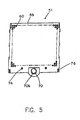
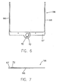
- the base housing 51 shown in Figs. 3-5 is a rectangularly shaped planar plate of insulating plastic or resin material 59 having a U-shaped metal frame (see Figs. 6 and 7) embedded therein as its reinforcement.
- the U-shaped metal frame 58 is a single piece stamped and formed from sheet metal so that it has opposite legs 66 and a cam plate 67 integrally connecting these opposite legs 66.
- the molded plate of insulating resin material 59 covering the U-shaped frame has terminal receiving cavities 60 arranged in the same lattice pattern or array, as shown in Fig. 5, as the array of pins 118 of PGA package 117.
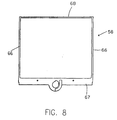
- Fig. 8 shows a second embodiment of a metal frame in which opposite legs 66 are connected to each other by lower cam plate 67 and an inter-connection beam 68 at the opposite ends of legs 66.
- the lower cam plate 67 has an axle bearing hole 70 therein for rotatably accommodating the rotary axle 69 (Figs. 30-33) of the eccentric cam member 53.
- the axle bearing hole 70 is elliptical rather than being perfectly circular, and has a notch 71 (Figs. 9 and 10) on its circumference. It also has a J-shaped reinforcement 72 formed along part of its circumference, starting from the point diametrically opposite to the notch and extending around hole 70 almost to the notch 71.
- the metal frame 58 is embedded in a generally planar sheet of insulating resin material or plastic 59, but the annular area 70a surrounding the axle bearing hole 70 of the lower cam plate 67 is exposed from the molded plastic. More specifically, referring to Figs. 9 and 10, the upper surface of the lower cam plate 67 is exposed at the surrounding area 70a of the axle bearing hole 70 except for J-shaped reinforcement 72, which is embedded in the insulating plastic material 59. As a result, there is a stepwise discontinuity or riser formed between the exposed and unexposed portion of surrounding area 70a that acts as a retainer surface 73.
- the lower surface of the lower cam plate 67 has an annular circumferential area 70b exposed around the axle bearing aperture 70 (see Figs. 5 and 10).
- the lower surface of the base housing 51 has positioning bosses or standoffs 74 molded thereon, and catch holes 76 formed at the corners thereof for receiving metal fitting or solder nails 75 therein.
- the molded plate of insulating plastic material 59 extending between the opposite legs 66 of the metal frame 58 has terminal-receiving holes or cavities 60 arranged in a grid as seen from Figs. 2, 3 and 5.
- the terminal-receiving cavities 60 are generally rectangular in shape, with a rectangular portion 60a extending through the total thickness of the molded plate 59.
- the terminal receiving cavities 60 have semicircular portions 77 and 78 on opposite sides thereof and extending down from the top surface of molded plate 59 about one half of the thickness thereof, while communicating with rectangular portion 60a of the terminal cavity 60.
- Semicircular portion 77 is an insertion section that allows a selected lead pin 118 of a pin grid-array package 117 to be inserted without contacting a terminal 57 located in terminal-receiving cavity 60. Thus, substantially no insertion force is required.
- Terminal retention slots 79 extend down from the bottom of insertion section 77 to the bottom of the base housing 51.
- the base housing 51 has projections 80 extending from the bottom surface thereof as will be described in further detail below.
- each terminal 57 is stamped and formed of sheet metal material and includes a generally U-shaped section formed of a base 82 and a pair of contact arms 85 integrally connected to and extending up from the base 82.
- the contact arms 85 are angled toward each other so that they are spaced further apart adjacent base 82 than at their distal free end.
- At the distal end of each contact arm is an inwardly bulged contact area or section 87 which is formed to create a high pressure contact area which engages a pin 117 of a PGA package 118.
- the contact area 87 tapers away from the terminal retention section 84 as indicated at 88 in Fig. 16 in order to create a lead-in to receive the pin 117 of a PGA package 118.
- Each terminal also includes a solder tail 81 that extends from one lateral side of base 82.
- the solder tail extends initially away from base 82 and then curves downward until it angles downward relative to the lower surface of the base housing 51 in a generally linear manner to provide an appropriate tail for surface mount soldering on the surface of a printed circuit board.
- An end portion of the solder tail may extend upwards a short distance in order to form a generally circular surface mount contact section 86.
- the contact section 86 may be surface mount soldered to conductive pads on the printed circuit board in a known manner.
- the terminals also include a terminal retention section for engaging a respective terminal retention slot 79 in the base housing 51 in order to secure the terminal within the housing.
- the terminal retention section 84 extends generally upward from the base 82 generally in parallel with the contact arms 85 of the terminal.
- An arcuate stress-dispersion arm 83 is located between the base 82 and the terminal retention section 84.
- Each of the contact arms 85 is approximately as tall as the thickness of the base housing assembly and the terminal retention section 84 is as tall as approximately one-half the thickness of the base housing. As a result, the terminal retention section 84 does not enter the pin-receiving cavity within the base mold.
- the terminals are secured to a carrier strip 89 by a pair of joints 90 so that the terminals are consistently positioned in a parallel arrangement.
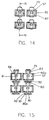
- the terminals can be separated from the carrier strip 89 by cutting the joints 90 at weakened portions 91 (see Figs. 19 and 22).
- a divergent projection 92 remains projecting from each terminal after the joints 90 are cut at their weakened portions 91.
- These divergent projections 92 are located adjacent to projections 80 on the bottom of the base housing 51 (Fig. 15). In fact, the pair of divergent projections 92 extend around the projections 80 of the base housing so that there is a small gap 93 between the side walls 80 of the divergent projections 92 and the projection 80.
- Figs. 23 to 27 illustrate the structure of the molded cover while Fig. 28 shows a metal stiffener 61 and Fig. 29 shows an upper cam plate 62 which are both components of the cover.
- metal stiffener 61 is formed from sheet metal and has a plurality of apertures arranged in a lattice pattern.
- a longitudinally elongated hole 99 is formed at the center of one lateral side of stiffener 61.
- the longitudinally elongated hole 99 has an L-shaped slit 100 extending therefrom, which defines a deflectable leg 101 with a locking-finger 101a projecting into the aperture.
- the upper cam plate 62 has a laterally (relative to the socket 50) elongated hole 102 formed adjacent its center and generally aligned with elongated hole 99 of stiffener 61.
- the length of the longer axis of the longitudinally elongated hole 99 of stiffener 61 is substantially equal to the length of the shorter axis of the laterally elongated hole 102, as best seen from Fig. 23.
- the sides of laterally elongated hole 102 accommodate snugly the eccentric cam 104 of the eccentric cam member 53 to function as a cam follower whereas the sides of longitudinally elongated hole 99 accommodate snugly the rotary axle 69 of the eccentric cam member 53 to function as a second cam follower.
- the stiffener 61 and upper cam plate 62 may be secured together in a spaced apart relationship by inserting metal pins 63 into holes 94 and 95 of the stiffener 61 and cam plate 62, respectively.
- slots 97 are upwardly divergent or tapered so that they are wider at their upper surface than their lower surface.
- insulating plastic or resin material is injected into the mold, resulting in the cover shown in Figs. 23-27.
- Portions of the metal stiffener 61 and upper cam plate 62 are embedded in insulating resin material 64 to form cover 52 with the upper surface of the metal stiffener 61 exposed, as best seen in Figs.26 and 27.
- the exposed upper surface of the metal stiffener 61 is preferably coated beforehand with an insulating material.
- the insulating resin material flows into the elongated holes 96 of the metal stiffener 61 and the elongated holes 97 of the overlying upper cam plate 62 to positively fasten these plates together as indicated at 103 in Fig. 27.
- the molded portion 64 of cover 52 is also upwardly divergent at 103 which acts to secure the stiffener 61 and the molded portion 64 together to create cover 52.
- the cover 52 also includes a plurality of through holes 56 formed in the insulating resin material 64 in registration with the apertures 65 of the metal stiffener 61. As seen in Fig. 26, each through hole 56 includes a first section with straight sidewalls and a second section 56a which is upwardly divergent in shape. The divergent opening 56a facilitates the guiding of the lead pin 118 of a PGA package 117 into socket 50.
- Figs. 30 to 33 show an eccentric cam member 53 for moving slidably the cover 52 on the underlying base housing 51.
- the center 0' of the eccentric cam 104 is spaced apart from the center 0 of the rotary axle 69 as best seen in Fig. 32.
- the eccentric cam member 53 has a vertical stop slot 106 at which the circumference of the eccentric cam 104 (or cam surface 105) and the circumference of the rotary axle 69 meet together.
- the eccentric cam 104 has a slot 107 on the top surface thereof for receiving a blade-like tool (not shown) such as a screwdriver.
- the rotary axle 69 has relatively long and short spaced apart ridge projections 108 and 109 formed thereon, respectively, projecting outward on the side diametrically opposite to the vertical engagement slot 106.
- the eccentric cam member 53 has a vertical insertion slot 110 adjacent to these ridge projections 108 and 109.
- the eccentric cam member 53 is positioned in the space defined by the laterally elongated hole 102 in cam plate 62 and longitudinally elongated hole 99 of the cover 52 as well as the axle bearing aperture 70 of the base housing 51.
- the height of the eccentric cam member 53 is generally equal to the combined thickness of base housing 51 and cover 52 at the location of cam member 53.
- Figs. 1, 2, 24 and 34 to 36 show L-shaped engagement pieces 54 depending from the opposite longitudinal sides of the cover 52.
- Three L-shaped engagement pieces 54 and generally evenly spaced along each longitudinal side of cover 52.
- Each L-shaped engagement piece 54 has a horizontal extension 111 (Figs. 34-36) that extends generally parallel to the overlying cover and terminates with a projection 112, which has a forwardly descending slope 113 formed thereon.
- the base housing 51 has complementary engagement projections 114 formed on the opposite longitudinal sides of the base housing and spaced apart so as to be engaged by engagement pieces 54 of cover 52.
- Each engagement projection 114 includes a cantilever-like extension extending generally parallel to the base housing 51, and terminates with a lower projection 115, which engages the upper projection 112 of the horizontal extension 111 of the L-shaped engagement piece 54 to retain the cover on base housing 51.
- the eccentric cam member 53 is fitted in the socket assembly by inserting the rotary axle 69 of the cam member 53 in the axle bearing hole 70 of the base housing 51 after passing through holes 99 and 102 of the cover 52.
- the eccentric cam member 53 is oriented so that the long and short ridge projections 108 and 109 (Figs. 31-33) are aligned with the notched portion 71 (Fig. 37) of the axle bearing hole 70 thereby avoiding the interference between the rotary axle 69 and the circumference of the axle bearing hole 70.
- the vertical insertion slot 110 of the rotary axle 70 is aligned with finger 101a of deflectable leg 101 which projects into the longitudinally elongated hole 99 of the metal stiffener 61.
- the slot 110 is dimensioned so as to be large enough to avoid interference with finger 101a during this assembly step.
- Figs. 39 and 40 show that the eccentric cam member 53 having been inserted into the socket assembly, passing through the openings in cover 52 and the underlying base housing 51.
- the long ridge projection 108 rides on the upper surface 70a adjacent axle bearing hole 70, thereby permitting rotation of the long ridge projection 108 therealong whereas short ridge projection 109 rides on the lower surface 70b adjacent axle bearing hole 70, thereby permitting rotation of the short ridge projection 109 there along (see Fig. 40).
- annular area 70a is sandwiched between long and short ridge projections 108 and 109.
- the eccentric cam 104 of the eccentric cam member 53 is located in laterally elongated hole or aperture 102 of upper cam plate 62 of cover 52 with its cam surface 105 confronting the inner circumference of aperture 102.
- the upper surface of the eccentric cam is generally flush with upper surface of the upper cam plate 62, and the lower surface of the rotary axle 69 is generally flush with the lower surface of the base housing 51. Counterclockwise rotation of the eccentric cam member 53 over 90 degrees completes the assembling of cam member 53 into socket 50.
- Rotation of the eccentric cam member 53 may be effected by fitting a screwdriver in slot 107 and by rotating the tool.
- the eccentric cam member 104 engages the cam surface of aperture 102, which causes cover 52 to slide linearly relative to base housing 51 in the direction indicated by arrow 116 in Fig. 39.
- Rotating the cam member 53 over 90 degrees aligns finger 101a with vertical engagement slot 106 to stop the rotation of the eccentric cam member 53, and hence the cover 52, at a predetermined position.
- Figs. 35, 41, 42 and 45 show that the eccentric cam member 53 in its locked/pin insertion position in which finger 101a engages vertical engagement slot 106.
- the horizontal extension 111 of each engagement piece 54 of the cover 52 had slid under cantilever-like engagement piece 114 of the base housing 51 until the forward projection 115 of the cantilever-like engagement piece 114 rides on the slope 113 of the upward projection 112 of the horizontal extension 111.
- the engagement piece 54 is yieldingly bent downward, and the cover 52 is pushed tightly against the base housing 51.
- the short ridge projection 109 rotates the lower surface 70b adjacent axle bearing hole 70 to reach the notch-free circumference of the axle bearing hole 70, thus permitting the short ridge projection 109 to engage the lower cam plate 67 of metal frame 58.
- the eccentric cam member 53 is prevented from rising by the short ridge projection 109, which engages the lower cam plate 67. This also contributes to the positive fastening of the cover 52 to the base housing 51.
- each through hole 56 of the cover 52 is aligned with a selected pin insertion cavity 77, which is adjacent to the opposed contact arms 85 of the terminals 57 in the terminal-receiving cavities 60.
- each lead pin 118 of a pin grid-array package 117 can be inserted into socket 50 with essentially no insertion force being applied to the lead pins 118.
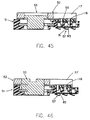
- Fig. 45 shows a pin grid-array package 117 located on the cover 52 with the lead pins 118 inserted in the pin insertion cavities 77 without any insertion force having been applied.
- the eccentric cam member 53 is rotated counterclockwise another 90 degrees. This additional 90 degrees of rotation causes the cover 52 and the PGA package 117 mounted thereon to slide (to the left in Fig. 46) to the contact engaging position shown in Figs. 36, 43, 44 and 46 so that the pins 118 of the PGA package 117 engage respective ones of terminals 57.
- the rotation is stopped when the long ridge projection 108 of the rotary axle 69 abuts the retainer surface 73 adjacent the circumference of axle bearing aperture 70 which thus stops the linear motion of cover 52 relative to base housing 51.
- the eccentric cam member 53 can rotate from the forceless-insertion position (Figs. 35, 41, 42 and 45) in which finger 101a of metal stiffener 61 of cover 52 engages vertical engagement slot 106 of the eccentric cam member 53 to the operational/contact engaging position (Figs. 36, 43, 44 and 46) in which the long ridge projection 108 of the rotary axle 69 abuts retainer surface 73 formed on the circumference of the axle bearing aperture 70 and the pins 118 of the PGA package 117 engage terminals 57.
- the angular range between these positions is 90 degrees.
- each and every through hole 56 of cover 52 is positioned immediately above the contact arms 85 of terminals 57 in the terminal-receiving cavities of the base housing 51.
- the sliding of the cover 52 bearing the pin grid-array package 117 from the insertion position shown in Fig. 45 to the contact engaging position shown in Fig. 46 brings the lead pins 118, which are inserted in the through holes 56 of the cover 52, between the contact arms 85 of a selected terminal 57, thus completing connection of the pin grid-array package 117 to the socket 50.
- each lead pin engages the opposed contact arms 85 of a selected terminal, it is forcedly driven into the space defined by the raised contact surfaces 87 of the opposite contact arms 85 while being guided smoothly into position by lead-in 88 which is divergent toward the pin insertion cavity 77.
- the space between raised contact surfaces 87 is dimensioned so that a lead pin therebetween is engaged with a contact pressure strong enough to assure that stable and reliable electric contact is established.
- terminals 57 permit the stress to be released by adding additional flexibility through stress-dispersion arm 83 positioned between base 82 and retention section 84.
- the remaining divergent projections 92 of the terminal 57 are positioned on opposite sides of projections 80 close to the opposite sloped ends 80a. These remaining divergent projections 92 of the terminal 57 abut the opposite slopes 80a of the projection 80 in order to further distribute stresses.
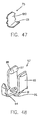
- Fig. 47 shows a metal fitting or solder nail 75 which may be positioned on the bottom of base housing 51 (Fig. 1).
- the upright leg 120 of the nail 75 is pushed into a slot 76 (Fig. 5) located at each corner of the base housing 51.
- the horizontal foot 121 of the nail 75 is soldered to a printed circuit board on which the socket 50 is mounted.
Landscapes
- Engineering & Computer Science (AREA)
- Microelectronics & Electronic Packaging (AREA)
- Coupling Device And Connection With Printed Circuit (AREA)
- Connecting Device With Holders (AREA)
- Structures For Mounting Electric Components On Printed Circuit Boards (AREA)
Applications Claiming Priority (2)
| Application Number | Priority Date | Filing Date | Title |
|---|---|---|---|
| JP36186798A JP3256898B2 (ja) | 1998-12-05 | 1998-12-05 | ピングリッドアレイパッケージ用ソケット |
| JP36186798 | 1998-12-05 |
Publications (2)
| Publication Number | Publication Date |
|---|---|
| EP1014506A2 true EP1014506A2 (fr) | 2000-06-28 |
| EP1014506A3 EP1014506A3 (fr) | 2001-04-04 |
Family
ID=18475123
Family Applications (1)
| Application Number | Title | Priority Date | Filing Date |
|---|---|---|---|
| EP99124290A Withdrawn EP1014506A3 (fr) | 1998-12-05 | 1999-12-06 | Connecteur enfichable zero force d'insertion destine a module à broches en grille |
Country Status (8)
| Country | Link |
|---|---|
| US (2) | US6254415B1 (fr) |
| EP (1) | EP1014506A3 (fr) |
| JP (1) | JP3256898B2 (fr) |
| KR (1) | KR100351086B1 (fr) |
| CN (1) | CN1129991C (fr) |
| MY (1) | MY122209A (fr) |
| SG (1) | SG102558A1 (fr) |
| TW (1) | TW430203U (fr) |
Cited By (4)
| Publication number | Priority date | Publication date | Assignee | Title |
|---|---|---|---|---|
| WO2003012929A1 (fr) * | 2001-07-30 | 2003-02-13 | Molex Incorporated | Support a matrice douilles-broches |
| WO2002065591A3 (fr) * | 2001-02-14 | 2003-03-06 | Molex Inc | Connecteur de boitier matriciel |
| EP1649550A1 (fr) * | 2003-07-25 | 2006-04-26 | Advanced Micro Devices, Inc. | Montage de compression et raccord a force d'insertion nulle pour dispositifs a circuits integres |
| CN104134902A (zh) * | 2013-05-03 | 2014-11-05 | 富士康(昆山)电脑接插件有限公司 | 电连接器 |
Families Citing this family (34)
| Publication number | Priority date | Publication date | Assignee | Title |
|---|---|---|---|---|
| US6851963B2 (en) * | 2001-02-22 | 2005-02-08 | Molex Incorporated | Pin grid array socket with reinforcement plate |
| JP3715545B2 (ja) * | 2001-04-19 | 2005-11-09 | タイコエレクトロニクスアンプ株式会社 | 電気コネクタ |
| US6960095B2 (en) * | 2001-04-25 | 2005-11-01 | Molex Incorporated | Pin grid array socket with kickback force resisting slide plate |
| US6431900B1 (en) * | 2001-06-08 | 2002-08-13 | Hon Hai Precision Ind. Co., Ltd. | Zero insertion force connector |
| US6338640B1 (en) * | 2001-09-12 | 2002-01-15 | Hon Hai Precision Ind. Co., Ltd. | ZIF mobile socket |
| US6616471B2 (en) * | 2001-09-21 | 2003-09-09 | Intel Corporation | Integrated horizontal cam lever for zero-insertion force (ZIF) socket actuation |
| US6527577B1 (en) * | 2001-12-07 | 2003-03-04 | Hon Hai Precision Ind. Co., Ltd. | CPU socket having separate retention member |
| US6475012B1 (en) * | 2001-12-18 | 2002-11-05 | Hon Hai Precision Ind. Co., Ltd. | Device for CPU socket actuation |
| US6579112B1 (en) * | 2002-03-27 | 2003-06-17 | Hon Hai Precision Ind. Co., Ltd. | ZIF socket with improved cam mechanism |
| TW584326U (en) * | 2002-04-30 | 2004-04-11 | Hon Hai Prec Ind Co Ltd | Electrical connector for CPU socket |
| TW549637U (en) * | 2002-06-06 | 2003-08-21 | Hon Hai Prec Ind Co Ltd | Connector |
| TW532634U (en) * | 2002-06-28 | 2003-05-11 | Hon Hai Prec Ind Co Ltd | Electrical connector for CPU socket |
| TW581330U (en) * | 2002-10-18 | 2004-03-21 | Hon Hai Prec Ind Co Ltd | Electrical connector |
| US6910908B2 (en) * | 2002-10-31 | 2005-06-28 | Tyco Electronics Corporation | Reinforced socket cover assembly |
| TW549656U (en) * | 2002-11-05 | 2003-08-21 | Hon Hai Prec Ind Co Ltd | Electrical connector |
| US6712634B1 (en) * | 2003-01-17 | 2004-03-30 | Tyco Electronics Corporation | Moment/bow reducing wear plate |
| US6692283B1 (en) * | 2003-02-11 | 2004-02-17 | Kuang-Chih Lai | Zero insertion/extraction force integrated circuit socket |
| TW568456U (en) * | 2003-05-16 | 2003-12-21 | Hon Hai Prec Ind Co Ltd | Electrical connector |
| TWM250387U (en) * | 2003-09-05 | 2004-11-11 | Hon Hai Prec Ind Co Ltd | Electrical connector |
| TWI275211B (en) * | 2004-02-20 | 2007-03-01 | Hon Hai Prec Ind Co Ltd | Electrical connector |
| TWI264151B (en) * | 2004-02-20 | 2006-10-11 | Hon Hai Prec Ind Co Ltd | Electrical connector |
| US7470147B2 (en) * | 2004-02-24 | 2008-12-30 | Intel Corporation | Spring biased socket system |
| US7018219B2 (en) * | 2004-02-25 | 2006-03-28 | Rosenau Steven A | Interconnect structure and method for connecting buried signal lines to electrical devices |
| CN2697853Y (zh) * | 2004-03-05 | 2005-05-04 | 富士康(昆山)电脑接插件有限公司 | 电连接器 |
| TWI245468B (en) * | 2004-03-26 | 2005-12-11 | Hon Hai Prec Ind Co Ltd | Electrical connector |
| CN200959466Y (zh) * | 2006-08-22 | 2007-10-10 | 富士康(昆山)电脑接插件有限公司 | 电连接器 |
| CN101369707B (zh) * | 2007-08-15 | 2012-10-31 | 富士康(昆山)电脑接插件有限公司 | 一种用于电连接器凸轮的制造方法 |
| TWM351468U (en) * | 2008-07-29 | 2009-02-21 | Hon Hai Prec Ind Co Ltd | Electrical connector |
| US7753707B1 (en) * | 2009-04-24 | 2010-07-13 | Lotes Co., Ltd. | Electrical connecting assembly |
| TWM382607U (en) * | 2009-09-30 | 2010-06-11 | Hon Hai Prec Ind Co Ltd | Electrical connector |
| CN201639075U (zh) * | 2009-11-02 | 2010-11-17 | 富士康(昆山)电脑接插件有限公司 | 电连接器的驱动构件 |
| CN201845926U (zh) * | 2010-07-13 | 2011-05-25 | 番禺得意精密电子工业有限公司 | 零插入力电连接器 |
| US8419460B2 (en) * | 2011-09-17 | 2013-04-16 | Suyin Electronics (Dongguan) Co., Ltd. | Electric connector |
| CN113690650A (zh) * | 2021-07-21 | 2021-11-23 | 番禺得意精密电子工业有限公司 | 电连接器 |
Family Cites Families (17)
| Publication number | Priority date | Publication date | Assignee | Title |
|---|---|---|---|---|
| US4343524A (en) * | 1980-06-30 | 1982-08-10 | Amp Incorporated | Zero insertion force connector |
| US4420205A (en) | 1981-09-14 | 1983-12-13 | Augat Inc. | Low insertion force electronic component socket |
| US4496205A (en) * | 1982-07-23 | 1985-01-29 | Thomas & Betts Corporation | Low or zero insertion force connector for multi-pin arrays |
| US4468072A (en) * | 1981-12-17 | 1984-08-28 | Thomas & Betts Corporation | Multi-pin zero insertion force connector |
| US5057031A (en) * | 1990-08-15 | 1991-10-15 | Aries Electronics, Inc. | Zero insertion force pin grid array test socket |
| JPH0567485A (ja) * | 1991-09-06 | 1993-03-19 | Nec Corp | ソケツトコンタクト及びピン・グリツド・アレイ型lsi用ソケツト |
| US5380212A (en) * | 1992-08-14 | 1995-01-10 | Hewlett Packard Company | Conductive elastomeric interface for a pin grid array |
| US5387121A (en) * | 1993-09-13 | 1995-02-07 | Kurz; Edward A. | Zero insertion force socket |
| CA2115403C (fr) * | 1994-02-10 | 1998-08-04 | Fu-Yu Hsu | Connecteur electrique avec element femelle a force d'insertion nulle |
| US5569045A (en) * | 1994-02-10 | 1996-10-29 | Hsu; Fu-Yu | Electrical connector |
| US5762511A (en) * | 1994-10-11 | 1998-06-09 | Methode Eletronics, Inc. | Zero insertion force pin grid array socket |
| US5489217A (en) * | 1994-10-11 | 1996-02-06 | Methode Electronics, Inc. | Zero insertion force pin grid array socket |
| US5597319A (en) * | 1994-11-29 | 1997-01-28 | Methode Electronics, Inc. | Zero insertion force pin grid array socket |
| US5707247A (en) | 1995-10-12 | 1998-01-13 | Intel Corporation | Low-profile zero-insertion force socket |
| JP2995391B2 (ja) * | 1996-01-26 | 1999-12-27 | 日本航空電子工業株式会社 | Pga用ソケットコンタクトおよびその製造方法 |
| JP2772788B2 (ja) * | 1996-10-17 | 1998-07-09 | 株式会社エンプラス | Icソケット |
| US6164999A (en) * | 1997-07-30 | 2000-12-26 | Intel Corporation | Zero insertion force socket and method for employing same to mount a processor |
-
1998
- 1998-12-05 JP JP36186798A patent/JP3256898B2/ja not_active Expired - Fee Related
-
1999
- 1999-11-25 SG SG9905911A patent/SG102558A1/en unknown
- 1999-12-02 MY MYPI99005265A patent/MY122209A/en unknown
- 1999-12-03 US US09/454,145 patent/US6254415B1/en not_active Expired - Fee Related
- 1999-12-03 US US09/454,144 patent/US6296506B1/en not_active Expired - Fee Related
- 1999-12-04 TW TW088220714U patent/TW430203U/zh not_active IP Right Cessation
- 1999-12-04 KR KR1019990054966A patent/KR100351086B1/ko not_active Expired - Fee Related
- 1999-12-06 EP EP99124290A patent/EP1014506A3/fr not_active Withdrawn
- 1999-12-06 CN CN99124787A patent/CN1129991C/zh not_active Expired - Fee Related
Cited By (5)
| Publication number | Priority date | Publication date | Assignee | Title |
|---|---|---|---|---|
| WO2002065591A3 (fr) * | 2001-02-14 | 2003-03-06 | Molex Inc | Connecteur de boitier matriciel |
| WO2003012929A1 (fr) * | 2001-07-30 | 2003-02-13 | Molex Incorporated | Support a matrice douilles-broches |
| EP1649550A1 (fr) * | 2003-07-25 | 2006-04-26 | Advanced Micro Devices, Inc. | Montage de compression et raccord a force d'insertion nulle pour dispositifs a circuits integres |
| CN104134902A (zh) * | 2013-05-03 | 2014-11-05 | 富士康(昆山)电脑接插件有限公司 | 电连接器 |
| US9343836B2 (en) | 2013-05-03 | 2016-05-17 | Hon Hai Precision Industry Co., Ltd. | Electrical socket having improved cam |
Also Published As
| Publication number | Publication date |
|---|---|
| SG102558A1 (en) | 2004-03-26 |
| CN1129991C (zh) | 2003-12-03 |
| US6296506B1 (en) | 2001-10-02 |
| EP1014506A3 (fr) | 2001-04-04 |
| TW430203U (en) | 2001-04-11 |
| US6254415B1 (en) | 2001-07-03 |
| JP3256898B2 (ja) | 2002-02-18 |
| JP2000173736A (ja) | 2000-06-23 |
| MY122209A (en) | 2006-03-31 |
| KR100351086B1 (ko) | 2002-09-09 |
| CN1256532A (zh) | 2000-06-14 |
| KR20000047917A (ko) | 2000-07-25 |
Similar Documents
| Publication | Publication Date | Title |
|---|---|---|
| US6254415B1 (en) | Zero insertion force electrical connector | |
| JP3360178B2 (ja) | 一体的支持構造を有する電気コネクタ | |
| KR100343081B1 (ko) | 핀 격자 어레이 패키지용 소켓 조립체 및 이를 위한 단자 | |
| US6464525B2 (en) | Overtravel protection for ZIF electrical connector | |
| US6599140B1 (en) | Electrical connector assembly having a placement member | |
| US6325655B1 (en) | Electrical connector for a PGA package | |
| US20050191873A1 (en) | Metal contact LGA socket | |
| US6827586B2 (en) | Low-profile connector for circuit boards | |
| CA1294338C (fr) | Connecteur de carte de circuits pour coupe-circuit | |
| US6908328B2 (en) | Electrical connector with accurately secured contacts | |
| EP1006618A2 (fr) | Socle a force d'insertion zero (zif) pour des boitiers de reseau de grille a broche | |
| JP2004055464A (ja) | 低背型コネクタ | |
| US20010018286A1 (en) | Engagement means for ZIF electrical connector | |
| US6554634B1 (en) | Electrical contact for ZIF socket connector | |
| JPH08222335A (ja) | 電気コンタクト及びこれを使用したicソケット | |
| US6716060B2 (en) | Electrical connector with solder plate and pegs for PC board mounting | |
| US6929498B2 (en) | Electrical connector with mounting member and method of making same | |
| JP3131832B2 (ja) | ピングリッドアレイパッケージ用ソケット及び端子 | |
| US6846190B2 (en) | IC socket and gripping sheet used in the same | |
| JP3902119B2 (ja) | 電子部品用ソケット | |
| JP3148860B2 (ja) | ピングリッドアレイパッケージ用ソケット | |
| US6109932A (en) | Three-dimensional electrical interconnection system | |
| CN1416606A (zh) | 具有触点保持元件的连接器 | |
| JP2000058166A (ja) | コネクタ及びその製造方法 |
Legal Events
| Date | Code | Title | Description |
|---|---|---|---|
| PUAI | Public reference made under article 153(3) epc to a published international application that has entered the european phase |
Free format text: ORIGINAL CODE: 0009012 |
|
| AK | Designated contracting states |
Kind code of ref document: A2 Designated state(s): AT BE CH CY DE DK ES FI FR GB GR IE IT LI LU MC NL PT SE |
|
| AX | Request for extension of the european patent |
Free format text: AL;LT;LV;MK;RO;SI |
|
| PUAL | Search report despatched |
Free format text: ORIGINAL CODE: 0009013 |
|
| AK | Designated contracting states |
Kind code of ref document: A3 Designated state(s): AT BE CH CY DE DK ES FI FR GB GR IE IT LI LU MC NL PT SE |
|
| AX | Request for extension of the european patent |
Free format text: AL;LT;LV;MK;RO;SI |
|
| RIC1 | Information provided on ipc code assigned before grant |
Free format text: 7H 01R 13/193 A, 7H 01R 13/115 B, 7H 01R 12/16 B, 7H 05K 7/10 B |
|
| STAA | Information on the status of an ep patent application or granted ep patent |
Free format text: STATUS: THE APPLICATION HAS BEEN WITHDRAWN |
|
| 18W | Application withdrawn |
Withdrawal date: 20010831 |