EP1014526A2 - Procédé associé au relais de protection et relais de protection - Google Patents
Procédé associé au relais de protection et relais de protection Download PDFInfo
- Publication number
- EP1014526A2 EP1014526A2 EP99660191A EP99660191A EP1014526A2 EP 1014526 A2 EP1014526 A2 EP 1014526A2 EP 99660191 A EP99660191 A EP 99660191A EP 99660191 A EP99660191 A EP 99660191A EP 1014526 A2 EP1014526 A2 EP 1014526A2
- Authority
- EP
- European Patent Office
- Prior art keywords
- line
- fault
- busbar
- disappearance
- line section
- Prior art date
- Legal status (The legal status is an assumption and is not a legal conclusion. Google has not performed a legal analysis and makes no representation as to the accuracy of the status listed.)
- Granted
Links
Images

Classifications
-
- H—ELECTRICITY
- H02—GENERATION; CONVERSION OR DISTRIBUTION OF ELECTRIC POWER
- H02H—EMERGENCY PROTECTIVE CIRCUIT ARRANGEMENTS
- H02H3/00—Emergency protective circuit arrangements for automatic disconnection directly responsive to an undesired change from normal electric working condition with or without subsequent reconnection ; integrated protection
- H02H3/02—Details
- H02H3/06—Details with automatic reconnection
- H02H3/066—Reconnection being a consequence of eliminating the fault which caused disconnection
-
- H—ELECTRICITY
- H02—GENERATION; CONVERSION OR DISTRIBUTION OF ELECTRIC POWER
- H02H—EMERGENCY PROTECTIVE CIRCUIT ARRANGEMENTS
- H02H3/00—Emergency protective circuit arrangements for automatic disconnection directly responsive to an undesired change from normal electric working condition with or without subsequent reconnection ; integrated protection
- H02H3/40—Emergency protective circuit arrangements for automatic disconnection directly responsive to an undesired change from normal electric working condition with or without subsequent reconnection ; integrated protection responsive to ratio of voltage and current
-
- H—ELECTRICITY
- H02—GENERATION; CONVERSION OR DISTRIBUTION OF ELECTRIC POWER
- H02H—EMERGENCY PROTECTIVE CIRCUIT ARRANGEMENTS
- H02H7/00—Emergency protective circuit arrangements specially adapted for specific types of electric machines or apparatus or for sectionalised protection of cable or line systems, and effecting automatic switching in the event of an undesired change from normal working conditions
- H02H7/26—Sectionalised protection of cable or line systems, e.g. for disconnecting a section on which a short-circuit, earth fault, or arc discharge has occured
-
- G—PHYSICS
- G01—MEASURING; TESTING
- G01R—MEASURING ELECTRIC VARIABLES; MEASURING MAGNETIC VARIABLES
- G01R31/00—Arrangements for testing electric properties; Arrangements for locating electric faults; Arrangements for electrical testing characterised by what is being tested not provided for elsewhere
- G01R31/50—Testing of electric apparatus, lines, cables or components for short-circuits, continuity, leakage current or incorrect line connections
- G01R31/52—Testing for short-circuits, leakage current or ground faults
-
- G—PHYSICS
- G01—MEASURING; TESTING
- G01R—MEASURING ELECTRIC VARIABLES; MEASURING MAGNETIC VARIABLES
- G01R31/00—Arrangements for testing electric properties; Arrangements for locating electric faults; Arrangements for electrical testing characterised by what is being tested not provided for elsewhere
- G01R31/50—Testing of electric apparatus, lines, cables or components for short-circuits, continuity, leakage current or incorrect line connections
- G01R31/58—Testing of lines, cables or conductors
Definitions
- the present invention relates to a method and protective relay according to the preambles of the independent claims 1, 4, 11, 16 and 17.
- the known solutions often include a so-called auto-reclosing relaying which recloses a switch a while after it has opened. Since most of the faults in an open-wire network are electric arc faults, which disappear when the faulty line is disconnected for a short time, the distribution of electricity can often be continued by means of auto-reclosing.
- One disadvantage is that sometimes the fault does not disappear when the switch is open. Then the switch is closed against the fault and new relay operation and the opening of the switch are required immediately. In such a case, it is useful to know when the disconnecting of the line has led into the elimination of the fault, so that unnecessary auto-reclosings can be avoided.
- the line comprises a small-scale power station for decentralized power feed. Then, voltages behind the switch do not essentially change when the switch opens. The small-scale power station can then continue to feed the fault also when the switch of the line is open. Since the small-scale power station cannot feed fault current as much as the whole network, there are better chances for the fault to disappear by itself when the line switch has opened. This is the case particularly in the earth fault. In many cases it is thus convenient to keep the small-scale power station behind the open switch in operation for some time, whereby the probability of the disappearance of the fault by itself grows. In the best case the fault disappears and the consumers on the line are not left without electricity for one moment. The problem is then to recognise when the fault disappears from the line.
- a busbar, line or line arm at substations, switching substations and disconnector satellite substations can often get feed from two or more directions to their. If an earth fault occurs in the network, and none of the protective relays or fault indicators of the line or line arm indicates that the fault is on a specific line or line arm, it can be concluded that the fault is on the feed side. Then, the feed switch is usually opened and the switch of another feed is closed. There is a danger, however, that the fault is between the feed switch and the line switch, i.e. on the busbar of a substation or switching station or inside a disconnector satellite substation. Therefore, when the feed is changed, it is important to be able to detect on which side of the opened feed switch the fault is and not to close the switch of another feed, if the fault is on the busbar or inside the disconnector satellite substation.
- the opening of the line switch may cause resonance to the line.
- the resonance frequency depends on the values of the total capacitance and total inductance of the line. Resonance may cause overvoltages to the line and damage the components on the line. It is important that such a resonance is recognised so that the network topology can be selected such that resonances do not occur when the lines and line sections are disconnected. Traditionally there have been no methods to achieve this purpose, since voltages have not usually been measured from the disconnected lines in the distribution network.
- the switch can at first be held open for a short time, e.g. 150 ms, and then the auto-reclosing can be made. It the fault is eliminated by this so-called high speed automatic reclosing, the switch can be held closed and the power distribution can be continued as usual. If the line still has the fault, the switch is reopened for a longer time, e.g. for 1 minute. Then the switch is closed again. If the fault is eliminated by this so-called delayed auto-reclosing, the switch can be held closed and the power distribution can be continued as usual. Otherwise the relay trips the line definitively out of the network and it is set out to find the fault.
- the simple auto-reclosing sequence described above however, they all have a common feature that the lengths of the dead times are set in advance.
- the length of dead time in high speed automatic reclosing usually equals about few hundreds of milliseconds and the length of dead time in delayed auto-reclosing few minutes.
- the voltage on the line behind the open switch which voltage is caused by motor loads on the line, has not traditionally been taken into account in any other ways but with sufficiently long dead times of auto-reclosing.
- the problem is to detect when the fault has been eliminated.
- the location of the fault is traditionally concluded by means of an over-current criterion: if it is detected that fault current flows through the opening switch, the fault is concluded to be located behind the switch. Then the closing of another feed switch is prevented as it would lead to a connection against the fault.
- the method of the publications also has the disadvantage that the detection of the quenching of an electric arc is not based on unambiguous and exact criteria.
- the use of neural network technology is thus suggested in the publications.
- This has the disadvantage that according to the operational principle of neural networks the operation is partly unanticipated.
- the instructing of the neural network is a demanding task as well, and the neural network instructed by the voltage recordings of one electrical power network does not necessarily operate optimally in another network.
- the voltage of the faulty phase of a medium-voltage distribution line may also rise, but only when the line has enough motor load or generators that are connected to a decentralized power feed and that induce a three-phase alternating voltage to the line, while the switch is open. Even when the line has motor load, the voltage of the faulty phase does not necessarily rise. This is because the amplitude of the three-phase voltage induced by the motors often decreases rapidly, whereby the voltage increase of the faulty phase that is otherwise caused by the elimination of the fault is cancelled as a result of a general decrease of voltages.
- Another method described in the publication is based on the switch opened in three phases being closed in such a manner that one phase is closed at first. Thus, voltages are induced also to the open phases. If it is detected that the voltages of the two phases follow each other, it can be concluded that there is a short circuit and a three-phase auto-reclosing is not made. Thus, the purpose of this method is not to detect the disappearance time of the fault during the dead time of the auto-reclosing but to ensure the disappearance of the fault only when making the auto-reclosing.
- Patent SU 607305 A 19780424 introduces a method, in which the length of the dead time of the auto-reclosing is determined by the amount of power transferred through the line before the fault. The higher the transferred power, the shorter a dead time is set for the auto-reclosing. This does not naturally make the fault to disappear more easily but aims at improving the stability of the network.
- Patent US 5,805,400 determines the length of the dead time of an auto-reclosing in such a manner that the margin between the operational point and the point where the stability is losed is taken into account, so that the danger of losing stability can be minimised when making the auto-reclosing.
- Patent US 5,543,995 introduces a method, by which the breaking of a conductor of a transmission line can be detected by estimating the voltage of the faulty section by means of voltage and current measurements taken from both ends of the line and the auto-reclosing can be prevented, if a break in the conductor is detected.
- this method the disappearance of short circuit and earth faults cannot be detected when the line is disconnected from the net-work.
- a variety of known methods are used to disconnect a faulty section from a distribution line.
- One method is to calculate the location of the fault in the network by means of the measurements taken from the beginning of the line and to disconnect the faulty line section with remote-controlled disconnectors. As there is not usually sufficiently fast communication available, the faulty line section cannot be disconnected from the network during the dead time of the high speed automatic reclosing.
- Another known method of disconnecting a faulty line section is to apply switches along the line, which utilize local logic.
- the switches open when the voltage exits during the dead time of the high speed automatic reclosing and close again as the voltage returns. First the switch nearest to the fault closes and after that the switches behind it close one by one. As the switch located immediately before the fault section closes, fault current starts to flow again, and this causes the relay at the beginning of the line to trip and the switch which closed the last to lock open. In the next auto-reclosing other switches close, and the distribution of electricity is returned to that section of the line which is not faulty.
- a drawback of the known solutions is that before the switch is closed, usually nothing is known about the elimination of the fault.
- dead time cannot be determined to be very short, so that the voltages generated by loading motors would have enough time to damp on the line and the ionisation caused by the electric arc would have enough time to exit from the faulty section.
- longer dead times usually cause more harm to consumers of electricity.
- compromises have to be made between different opinions when selecting the length of dead time, which leads to unsuccessful auto-reclosings, on one hand, and also unnecessary switch controls, as the fault has not have time to disappear before the switch is closed.
- the distribution interruption may also be far too long for the disappearance of the fault, if the fault disappears soon after the switch has been opened.
- a drawback of the traditional solutions is also that the disappearance of the fault depends on the load of the line. If there are several motors as load, the voltage on the line may remain the same a long time after the switch has opened, which weakens the chances of the fault to disappear. Sometimes loads may be mainly heating or lighting loads, which do not maintain the voltage behind the switch. In the latter case, the switch could thus be reclosed faster, but in the traditional solutions, the features of the loading cannot be taken into account this way.
- a line may also comprise generators connected to a decentralized power feed, which may maintain voltage and thus prevent the fault from disappearing.
- a wind power station can be mentioned, whose operation depends naturally on wind conditions, and the chances of the fault to disappear by itself may vary considerably according to the situation. The traditional solutions cannot take this kind of situation into account.
- the closing of another feed switch is prevented, if it is detected that fault current has passed through the opened switch.
- This method is not comprehensive, since it is possible that the fault is located between the opening switch and the measuring point of current. Then the fault current is not detected but the fault, however, is not eliminated by opening the switch.
- Another feed switch is then closed against the fault, which is naturally harmful.
- the reliability of the solution based on the use of the overcurrent criterion depends also on whether the locking message sent by the device measuring overcurrent arrives at the feed changing device. If the locking message does not arrive there, the switch of another feed is closed against the fault with harmful effects.
- Said method of auto-reclosing based on measuring voltage includes the following weaknesses.
- the method is based on measuring the frequency content of the voltage of a faulty phase and instructing a neural network to recognise the disappearance of a so-called secondary electric arc that is lit at the phase disconnected from the network.
- a secondary electric arc is caused by the fact that through the capacitance between the phases, an alternating voltage is connected to the phase disconnected from the network.
- the method is only applicable to a phase-to-earth fault and cannot be employed in three-phase auto-reclosings.
- a drawback of the traditionally used methods of disconnecting a faulty section of a transmission line is the slowness.
- the solution based on fault location and remote-controlled disconnectors requires a communication connection from the disconnectors to a substation or a control room.
- the building of a signalling system to all disconnector satellite substations is, however, expensive.
- the accuracy of the fault distance calculation depends on many factors, e.g. on the measurement accuracy of currents and voltages and the accuracy of the line parameters used in the calculation. It is thus in practice possible that a faulty section between disconnectors cannot be located properly.
- the solutions based on local logic for disconnecting a faulty line section do not require a fast communication, but as the locating of the faulty section is based on phased test connections of disconnectors and on another relay opeartion resulting thereof, a fairly long interruption in the distribution of electricity cannot be avoided.
- the solutions based on local logic have traditionally only been applied in delayed auto-reclosing, if the fault has not disappeared by means of a high speed automatic reclosing.
- the object of the present invention is to provide a method by which the above drawbacks can be avoided and to enable the implementation of auto-reclosings and feed changes in a more reliable way.
- This object is achieved by the method of the invention, which method is characterized by further comprising the steps of: measuring voltages from the disconnected line, line section or busbar, forming parameters describing the state of the disconnected line, line section or busbar from the measured voltages, and concluding, on the basis of the parameters, the disappearance or possibility of disappearance of the fault of the disconnected line, line section or busbar.
- the invention is based on the idea that when the feed is switched off from the line or line section, the line or line section does not immediately become dead, but the motors loading the line function as generators inducing alternating voltages to the line.
- the invention enables the detection of the disappearance or existence of the fault, while the switch is open in three phases. Then if the fault disappears and the switch is opened, the length of dead time can be rapidly minimised. If it deals with a permanent fault or a fault which disappears slowly, the switch can be held open longer.
- the drawback of the traditional solution of having to compromise when the length of dead time is set is avoided since the length of dead time is set according to the fault in question and not on the basis of statistical observations or experience.
- the disappearance of the fault by itself can also be utilized in a situation in which the line comprises a small-scale power station.
- the small-scale power station need not be immediately switched off when the line switch opens, but it can be waited until the fault has disappeared. If the fault disappears by itself, interruptions in the power distribution can be avoided.
- the invention In connection with a feed change, the invention enables the detection of the location of the fault on a busbar or inside a disconnector satellite substation also in cases in which it is located between the switch and the measuring point of current.
- the solution of the invention also improves the reliability of the feed change automatics, as the operation no longer depends on the locking message, indispensable in the traditional solution, coming from the over-current relay of the feed.
- the solution of the invention is implemented by means of the measurements of signals which have either a fundamental frequency or a lower frequency, whereby the used technology is reliable and preferable.
- the method of the invention can be applied to detect the elimination of two- and three-phase faults during the dead time of auto-reclosing also in connection with a three-phase switch operation.
- the solution of the invention also takes the effect of motor loads into account by permitting the auto-reclosing to take place only after the fault has disappeared or voltages generated by the motors have decreased so much that the disappearance of electric arc faults becomes possible.
- the solution of the invention enables the rapid disconnection of the faulty line section by means of local automatics without a need for fast signalling systems.
- the solution of the invention does not, unlike the method based on the calculation of the fault section, require the knowledge of line parameters nor accurate current and voltage measurements. Only the measurements of voltages are needed, but they do not have to be accurate in order to be able to detect whether the fault has disappeared from the line section concerned.
- the invention also relates to a method according to the independent claim 4.
- the inventive idea of determining the state of an electrical power network can be used in connection with all connections in the network, whereby the tendency of the infallible network to resonant overvoltages can be detected.
- the invention further relates to a method according to the independent claim 11. According to the method, parameters based on voltages are formed from the voltages affecting on both sides of a switching device.
- the invention further relates to a protective relay comprising a switching element to disconnect and connect a faulty line, line section or busbar in three phases, whereby the protective relay is characterized in that the protective relay further comprises a voltage determination element adapted to determine the magnitude of voltage in an electrical power network in connection with the protective relay, and a processing element adapted to form parameters describing the state of the disconnected line, line section or busbar and to conclude the disappearance or possibility of disappearance of the fault of the disconnected line, line section or busbar.
- the invention further relates to a protective relay according to the independent claim 17, by which protective relay the advantages provided by the method of the independent claim 11 are achieved by means of a simple structure.
- a fault is detected on a line or line section of an electrical power network.
- the fault can be e.g. a short circuit or an earth fault which affects the normal operation of the electrical power network.
- the faulty section is disconnected from the other network, i.e. the faulty section is separated.
- the disconnection takes place in a protective relay or in a switching device in connection with it, which may be a mechanical switching element or a semiconductor switch, for example.
- voltage is measured from the disconnected line or line section.
- Voltage is measured by means of a voltage determination element adapted to the protective relay or to its connection.
- voltage is thus measured from a disconnected line or line section. From the measured voltages, parameters describing the state of the disconnected section are formed. The parameters are formed in a processing element of the protective relay, which processing element is in connection with the voltage determination element.
- the processing element concludes, on the basis of the parameters, the disappearance or possibility of disappearance of the fault of the disconnected line or line section.
- the parameters are formed according to the preferred embodiment of the invention in such a manner that the amplitude magnitude of a fundamental-frequency component of one or more phase or main voltages of the disconnected line or line section is determined.
- the forming of parameters may further comprise the step of comparing predetermined amplitude magnitudes with each other.
- the line or line section disconnected according to the preferred embodiment of the invention is reconnected to the network after a predetermined time has passed.
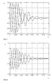
- Figures 1 and 2 show examples of the voltage behaviour of a line or line section disconnected from the network in a situation in which the fault does not disappear while the switch is open.
- Figure 1 shows phase voltages measured from the line after the line has been disconnected as a result of a two-phase short circuit. The switch opens approximately at the instant 0.03 s, but the short circuit between the two phases does not disappear immediately. The voltages of the faulty phases follow each other, which indicates that the fault is still affecting.
- Figure 2 shows main voltages measured from the line after the line has been disconnected as a result of a two-phase short circuit.
- the switch opens approximately at the instant 0.03 s, but the short circuit between the two phases does not disappear immediately. Since one main voltage remains low, this means that two phases are still in a short circuit.
- the main voltages of the figure relate to the phase voltages of Figure 1.
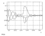
- Figure 5 relates to the disappearance of a three-phase short circuit after the opening of the switch. All main voltages increase rapidly, when the short circuit disappears.
- Figure 5 shows main voltages measured from the line after the line has been disconnected as a result of a three-phase short circuit.
- the switch opens approximately at the instant 0.68 s, but the short circuit disappears only at the instant 0.75 s, which can be seen as a sudden increase in the main voltages.
- a parameter according to the method of the invention is, for example, a relation of the amplitude of a fundamental frequency component of the main voltage between the phases in a two-phase short circuit to the amplitude of a fundamental-frequency component of the highest main or phase voltage.
- the disappearance of the two-phase short circuit can be concluded from the fact that the voltages of the faulty phases are no longer the same.
- the disappearance of the two-phase fault can be detected without any switching measures and by utilizing the measurements of the voltages induced by a motor load.
- Another possible parameter is formed by the amplitudes of all fundamental frequency components of the phase or main voltages or the amplitude and frequency of the component having the greatest amplitude in the frequency spectrum of all phase or main voltages.
- the disappearance of the three-phase short circuit is manifested in the sudden rise in all phase or main voltages.
- a parameter may also be the biggest instantaneous value of all phase and main voltages, the frequency of the component having the greatest amplitude in the frequency spectrum of the zero voltage or the time between two successive sign reversal points of the zero voltage.
- the disappearance of a phase-to-earth fault can be detected by the method of the invention on the basis of the following criteria.
- the earth fault has disappeared, if the frequency of the component having the greatest amplitude in the frequency spectrum of the zero voltage goes below a predetermined limit, or if the time between two successive sign reversal points of the zero voltage exceeds a predetermined limit.
- the criteria for detecting the disappearance of a phase-to-earth fault can also be applied to detect the absence or disappearance of a ground contact in connection with two-phase and three-phase faults.
- the resonant overvoltage of a line or line section is determined and the personnel of the electrical power network is informed of either the appearance of the resonant overvoltage or its magnitude and/or frequency.
- Resonant overvoltages can be identified in such a manner that the highest instantaneous value of one or all main or phase voltages or the amplitude of the wave component having the greatest amplitude exceeds a predetermined limit.
- a possibility of the appearance of resonant overvoltages in connection with switching measures of the network is already known.
- the appearance of resonant overvoltages on a disconnected line or busbar of a distribution network is detected by directly measuring the voltages of said line sections whenever the switch or other switching device opens. This determination of the resonant overvoltage can also be applied when it does not deal with a fault situation nor an auto-reclosing.
- the same or a different feed can be switched on according to a preferred embodiment of the invention at the substation or disconnector satellite substation of the distribution network. If the fault disappeared immediately when the switch opened, the fault was on the feed side, when it is better to change the feed. And if the fault disappeared only some time after the switch opened, the fault was not on the feed side, and the same feed can safely be switched on again. If it cannot be detected that the fault has disappeared, the switch is not connected at all for safety reasons or one of the supplies can be switched on after a predetermined time has passed since the conditions for the disappearance of the fault were created.
- a faulty line section can be disconnected from the network by means of disconnectors controlled by local automatics.
- the voltage measurements and the conclusions based on them are made separately for the line sections located on different sides of the disconnector.
- the disconnector is opened, when the parameters calculated from the voltages indicate that the fault was produced in the electrical power network. Then the disconnector is rapidly reclosed, if the voltages on both sides of the disconnector indicate that there is not a fault on said line sections.
- the disconnector can be closed already during the dead time of the high speed automatic reclosing, whereby another auto-reclosing and phased closings of the disconnectors need not be performed at all, and there will be no other relay operation nor an interruption in the feed resulting thereof As a result there is a considerably shorter interruption in the distribution than in the traditional method based on local logic.
- the method of the invention can basically be also employed in auto-reclosings that are made in connection with earth faults of an underground system, if it is detected that by employing the method of the invention the earth fault has disappeared.
- the method also enables a rapid return of the feed at the substation, switching substation or disconnector satellite substation also when the fault is located behind the opened switch, but it disappears when the switch opens. The information on the disappearance of the fault is not available in the traditional solutions, and the rapid feed return would require risk-taking.
- the solution of the invention may create an additional criterion for detecting the disappearance of the fault.
- the solution of the invention can thus be employed to support the known method for improving reliability.
- the method of the invention requires the measurement of voltage from the line behind the switch connected to the protective relay, and not from the busbar system, as usual. Then an additional voltage measuring device is needed to implement the auto-reclosing relaying according to the invention, the voltage measuring device measuring the voltage behind the switch. On the other hand, more and more voltage detectors or sensors behind the switch are also used in other purposes, whereby the solution of the invention does not cause extra costs. In many new switchgear the voltage measurement from each line behind the switch is already a standard solution. Further, it is to be noted that the solution of the invention applied to feed change relaying of sub-stations and switching stations operates specifically by means of the measurements of busbar voltages, whereby no additional voltage measuring devices are required.
- the protective relay do not perform an auto-reclosing at all, unless it can be detected that the fault has disappeared during the time when the voltages behind the switch still exceed a predetermined level, whereby the fault is interpreted to be permanent.
- the method of the invention can be applied for example in such a manner that the auto-reclosing is not made after the predetermined time has passed since the fault has disappeared, but it is waited until the voltages on both sides of the switch are in the same phase.
- This variation requires that at least one main voltage or phase voltage is measured before the switch, if the length of the dead time of the auto-reclosing is longer than a few seconds. If the dead time of the auto-reclosing is short, the voltages on the network side of the switch can be supposed to remain approximately in the same phases until the auto-reclosing is made.
- the disappearance of an earth fault can be detected by measuring one phase voltage, since the low-frequency zero voltage generated when the fault disappears is high in comparison with the fundamental-frequency phase voltages generated by the motors functioning as loads.
- the low-frequency zero voltage is summed to the fundamental-frequency voltage causing the time between the successive zero points to often become longer.
- the disappearance of the earth fault can thus also be detected by measuring the time between the successive zero points of one phase voltage. If it exceeds the determined limit, the earth fault is interpreted to have disappeared.
- the most preferable alternative in case of short circuits is to permit an auto-reclosing, when it is detected that the fault has disappeared, or the voltage has decreased so low that it is likely that the electric arc fault disappears.
- the electric arc may be lit between the faulty phases so long that the voltages are high enough to be measured. It is not thus always possible to detect the disappearance of the short circuit fault during the time that the voltages behind the open switch decrease. If the auto-reclosing were not made, unless it can be detected that the fault has disappeared, the auto-reclosing would not be made at all in many such cases in which the fault only disappears after the voltage has decreased considerably.
- the most preferable alternative depends on what kind of impedances between phase conductors and the earth there are on the line behind the open switch and how harmful an unsuccessful auto-reclosing against the earth fault is regarded to be. If the impedances between the phase conductors on the line and the earth enable a sufficiently great earth fault current on a disconnected line, the electric arc of the earth fault may be lit so long that the voltages behind the switch are sufficiently high to be measured. It is thus not always possible to detect the disappearance of the earth fault during the time the voltages behind the open switch decrease.
- the impedances between the phases of the line and the earth do not allow a considerable earth fault current on the disconnected line, the electric arc of the earth fault quenches and it is most likely that the fault disappears rapidly after the switch opens.
- the earth fault current usually decreases after the switch has opened so much that the electric arc quenches immediately. In such a case, it is preferable not to make auto-reclosings, unless it can be detected that the fault has disappeared. If the ground contact is maintained with a very low current, then it most likely deals with a permanent fault.
Landscapes
- Emergency Protection Circuit Devices (AREA)
Priority Applications (1)
| Application Number | Priority Date | Filing Date | Title |
|---|---|---|---|
| EP08159973.0A EP1981141B1 (fr) | 1998-12-17 | 1999-12-16 | Procédé en connexion avec un relais de protection et relais de protection |
Applications Claiming Priority (2)
| Application Number | Priority Date | Filing Date | Title |
|---|---|---|---|
| FI982741A FI109945B (fi) | 1998-12-17 | 1998-12-17 | Menetelmä suojareleen yhteydessä ja suojarele |
| FI982741 | 1998-12-17 |
Related Child Applications (2)
| Application Number | Title | Priority Date | Filing Date |
|---|---|---|---|
| EP08159973.0A Division EP1981141B1 (fr) | 1998-12-17 | 1999-12-16 | Procédé en connexion avec un relais de protection et relais de protection |
| EP08159973.0 Division-Into | 2008-07-09 |
Publications (3)
| Publication Number | Publication Date |
|---|---|
| EP1014526A2 true EP1014526A2 (fr) | 2000-06-28 |
| EP1014526A3 EP1014526A3 (fr) | 2002-02-27 |
| EP1014526B1 EP1014526B1 (fr) | 2010-05-26 |
Family
ID=8553145
Family Applications (2)
| Application Number | Title | Priority Date | Filing Date |
|---|---|---|---|
| EP08159973.0A Expired - Lifetime EP1981141B1 (fr) | 1998-12-17 | 1999-12-16 | Procédé en connexion avec un relais de protection et relais de protection |
| EP99660191A Expired - Lifetime EP1014526B1 (fr) | 1998-12-17 | 1999-12-16 | Procédé associé au relais de protection et relais de protection |
Family Applications Before (1)
| Application Number | Title | Priority Date | Filing Date |
|---|---|---|---|
| EP08159973.0A Expired - Lifetime EP1981141B1 (fr) | 1998-12-17 | 1999-12-16 | Procédé en connexion avec un relais de protection et relais de protection |
Country Status (3)
| Country | Link |
|---|---|
| EP (2) | EP1981141B1 (fr) |
| DE (1) | DE69942410D1 (fr) |
| FI (1) | FI109945B (fr) |
Cited By (8)
| Publication number | Priority date | Publication date | Assignee | Title |
|---|---|---|---|---|
| GB2355606A (en) * | 1999-07-14 | 2001-04-25 | Equipmake Ltd | Control of power transmission line |
| RU2279171C2 (ru) * | 2004-09-03 | 2006-06-27 | Московский государственный университет путей сообщения (МИИТ) | Устройство защиты контактной сети от токов короткого замыкания |
| RU2383982C1 (ru) * | 2008-12-24 | 2010-03-10 | Борис Алексеевич Аржанников | Контактная сеть |
| WO2012136274A3 (fr) * | 2011-04-08 | 2012-12-13 | Abb Research Ltd | Procédé de fonctionnement d'un réenclencheur |
| WO2015082632A1 (fr) * | 2013-12-04 | 2015-06-11 | Eaton Industries (Netherlands) B.V. | Refermeture automatique d'un disjoncteur pour courant alternatif |
| CN106786521A (zh) * | 2016-12-13 | 2017-05-31 | 国网江苏省电力公司淮安供电公司 | 一种计及单相断线谐振过电压的配电网薄弱支路判断方法 |
| EP3044843A4 (fr) * | 2013-09-12 | 2018-03-21 | Maragal, Deepak | Procédés et appareils pour détecter l'élimination de défaillances dans des lignes de transport compensées par réacteur en dérivation |
| RU2727706C1 (ru) * | 2019-07-19 | 2020-07-23 | Юрий Леонидович Беньяш | Способ координации действия защит питающих линий, смежных изолирующему сопряжению постоянного тока |
Families Citing this family (5)
| Publication number | Priority date | Publication date | Assignee | Title |
|---|---|---|---|---|
| RU2207688C2 (ru) * | 2000-11-13 | 2003-06-27 | Московский государственный университет путей сообщения | Схема защиты смежных фидеров тяговой сети постоянного тока (варианты) |
| RU2565053C1 (ru) * | 2014-09-25 | 2015-10-20 | Открытое Акционерное Общество "Системный Оператор Единой Энергетической Системы" | Способ включения линии электропередачи переменного тока |
| JP6715740B2 (ja) * | 2016-10-13 | 2020-07-01 | 株式会社日立製作所 | 電力系統の潮流監視装置、電力系統安定化装置および電力系統の潮流監視方法 |
| RU2710152C1 (ru) * | 2019-06-17 | 2019-12-25 | Федеральное государственное бюджетное образовательное учреждение высшего образования "Тюменский индустриальный университет" (ТИУ) | Способ передачи электроэнергии |
| US12176701B2 (en) * | 2022-11-18 | 2024-12-24 | Abb Schweiz Ag | Ground fault protection in a high resistance grounding system |
Family Cites Families (2)
| Publication number | Priority date | Publication date | Assignee | Title |
|---|---|---|---|---|
| US4710841A (en) * | 1985-10-23 | 1987-12-01 | Bottrell Gerald W | System for production of induction machines against damage from residual voltage effects |
| JP3284589B2 (ja) * | 1992-06-01 | 2002-05-20 | 株式会社日立製作所 | 送電線の保護方法及び保護継電装置 |
-
1998
- 1998-12-17 FI FI982741A patent/FI109945B/fi not_active IP Right Cessation
-
1999
- 1999-12-16 EP EP08159973.0A patent/EP1981141B1/fr not_active Expired - Lifetime
- 1999-12-16 DE DE69942410T patent/DE69942410D1/de not_active Expired - Lifetime
- 1999-12-16 EP EP99660191A patent/EP1014526B1/fr not_active Expired - Lifetime
Cited By (13)
| Publication number | Priority date | Publication date | Assignee | Title |
|---|---|---|---|---|
| GB2355606A (en) * | 1999-07-14 | 2001-04-25 | Equipmake Ltd | Control of power transmission line |
| GB2355606B (en) * | 1999-07-14 | 2003-08-06 | Equipmake Ltd | Power transmission line and method of control |
| RU2279171C2 (ru) * | 2004-09-03 | 2006-06-27 | Московский государственный университет путей сообщения (МИИТ) | Устройство защиты контактной сети от токов короткого замыкания |
| RU2383982C1 (ru) * | 2008-12-24 | 2010-03-10 | Борис Алексеевич Аржанников | Контактная сеть |
| WO2012136274A3 (fr) * | 2011-04-08 | 2012-12-13 | Abb Research Ltd | Procédé de fonctionnement d'un réenclencheur |
| EP3044843A4 (fr) * | 2013-09-12 | 2018-03-21 | Maragal, Deepak | Procédés et appareils pour détecter l'élimination de défaillances dans des lignes de transport compensées par réacteur en dérivation |
| CN105934858A (zh) * | 2013-12-04 | 2016-09-07 | 伊顿工业(荷兰)有限公司 | 自动重合闸交流断路器 |
| WO2015082632A1 (fr) * | 2013-12-04 | 2015-06-11 | Eaton Industries (Netherlands) B.V. | Refermeture automatique d'un disjoncteur pour courant alternatif |
| CN105934858B (zh) * | 2013-12-04 | 2019-03-29 | 伊顿工业(荷兰)有限公司 | 自动重合闸交流断路器 |
| US10374410B2 (en) | 2013-12-04 | 2019-08-06 | Eaton Intelligent Power Limited | Automatic reclosing alternating current circuit breaker |
| CN106786521A (zh) * | 2016-12-13 | 2017-05-31 | 国网江苏省电力公司淮安供电公司 | 一种计及单相断线谐振过电压的配电网薄弱支路判断方法 |
| CN106786521B (zh) * | 2016-12-13 | 2019-03-26 | 国网江苏省电力公司淮安供电公司 | 一种计及单相断线谐振过电压的配电网薄弱支路判断方法 |
| RU2727706C1 (ru) * | 2019-07-19 | 2020-07-23 | Юрий Леонидович Беньяш | Способ координации действия защит питающих линий, смежных изолирующему сопряжению постоянного тока |
Also Published As
| Publication number | Publication date |
|---|---|
| FI982741A0 (fi) | 1998-12-17 |
| FI109945B (fi) | 2002-10-31 |
| EP1981141A3 (fr) | 2014-04-09 |
| DE69942410D1 (de) | 2010-07-08 |
| FI982741L (fi) | 2000-06-18 |
| EP1014526B1 (fr) | 2010-05-26 |
| EP1981141B1 (fr) | 2014-11-26 |
| EP1014526A3 (fr) | 2002-02-27 |
| EP1981141A2 (fr) | 2008-10-15 |
Similar Documents
| Publication | Publication Date | Title |
|---|---|---|
| Novosel et al. | IEEE PSRC report on performance of relaying during wide-area stressed conditions | |
| US6667866B1 (en) | Virtual ground following single-phase trip | |
| US8180481B2 (en) | Autoloop system and method of operation | |
| CN104779594B (zh) | 小电流接地电力系统相间短路与单相接地综合保护方法 | |
| EP1014526B1 (fr) | Procédé associé au relais de protection et relais de protection | |
| US8817438B2 (en) | Recloser device and method of operation | |
| US9379534B2 (en) | Recloser device and method of operation | |
| Kaur et al. | Effects of distributed generation (DG) interconnections on protection of distribution feeders | |
| US8861154B2 (en) | Recloser device and method of operation | |
| US12113348B2 (en) | End of line protection | |
| Perez-Molina et al. | A comparison of non-unit and unit protection algorithms for HVDC grids | |
| CN100563075C (zh) | 同杆/平行双回线高阻接地保护方法及装置 | |
| CN111130071A (zh) | 适用于小电流接地系统的接地故障自愈系统 | |
| Mohanty et al. | Current restrained undervoltage protection scheme of converter dominated microgrids | |
| US11728638B2 (en) | Normally open tie pulse testing | |
| CN115333064A (zh) | 一种小电流接地故障多级保护方法 | |
| CN108134365A (zh) | 一种配电线路智能重合闸装置 | |
| Friend et al. | Effect of distribution automation on protective relaying | |
| JP2003209925A (ja) | 零点推移電流遮断事故防止システムとその方法 | |
| Gorozhankin et al. | Detection of Open-Phase Conditions on 110 kV Overhead Lines Using Antraks Short-Circuit Indicators | |
| Zhalefar | Adaptive single-phase reclosing in transmission lines | |
| Kobet et al. | Justifying pilot protection on transmission lines | |
| Toledo et al. | On evaluating single-phase tripping on distribution networks | |
| Mumtahina et al. | Evolving Protection Frameworks for Smaller Microgrids | |
| Dehghan Dehnavi | A Practical Method for Calculating the Reclosing Time in Long Lines with Reactors Case Study: Transmission Lines of Yazd Province |
Legal Events
| Date | Code | Title | Description |
|---|---|---|---|
| PUAI | Public reference made under article 153(3) epc to a published international application that has entered the european phase |
Free format text: ORIGINAL CODE: 0009012 |
|
| AK | Designated contracting states |
Kind code of ref document: A2 Designated state(s): AT BE CH CY DE DK ES FI FR GB GR IE IT LI LU MC NL PT SE Kind code of ref document: A2 Designated state(s): DE FR GB |
|
| AX | Request for extension of the european patent |
Free format text: AL;LT;LV;MK;RO;SI |
|
| PUAL | Search report despatched |
Free format text: ORIGINAL CODE: 0009013 |
|
| AK | Designated contracting states |
Kind code of ref document: A3 Designated state(s): AT BE CH CY DE DK ES FI FR GB GR IE IT LI LU MC NL PT SE |
|
| AX | Request for extension of the european patent |
Free format text: AL;LT;LV;MK;RO;SI |
|
| 17P | Request for examination filed |
Effective date: 20020524 |
|
| AKX | Designation fees paid |
Free format text: DE FR GB |
|
| 17Q | First examination report despatched |
Effective date: 20080130 |
|
| GRAP | Despatch of communication of intention to grant a patent |
Free format text: ORIGINAL CODE: EPIDOSNIGR1 |
|
| GRAS | Grant fee paid |
Free format text: ORIGINAL CODE: EPIDOSNIGR3 |
|
| GRAA | (expected) grant |
Free format text: ORIGINAL CODE: 0009210 |
|
| RAP1 | Party data changed (applicant data changed or rights of an application transferred) |
Owner name: ABB OY |
|
| AK | Designated contracting states |
Kind code of ref document: B1 Designated state(s): DE FR GB |
|
| REG | Reference to a national code |
Ref country code: GB Ref legal event code: FG4D |
|
| REF | Corresponds to: |
Ref document number: 69942410 Country of ref document: DE Date of ref document: 20100708 Kind code of ref document: P |
|
| PLBE | No opposition filed within time limit |
Free format text: ORIGINAL CODE: 0009261 |
|
| STAA | Information on the status of an ep patent application or granted ep patent |
Free format text: STATUS: NO OPPOSITION FILED WITHIN TIME LIMIT |
|
| 26N | No opposition filed |
Effective date: 20110301 |
|
| REG | Reference to a national code |
Ref country code: DE Ref legal event code: R097 Ref document number: 69942410 Country of ref document: DE Effective date: 20110228 |
|
| REG | Reference to a national code |
Ref country code: FR Ref legal event code: PLFP Year of fee payment: 17 |
|
| PGFP | Annual fee paid to national office [announced via postgrant information from national office to epo] |
Ref country code: DE Payment date: 20151211 Year of fee payment: 17 Ref country code: GB Payment date: 20151221 Year of fee payment: 17 |
|
| PGFP | Annual fee paid to national office [announced via postgrant information from national office to epo] |
Ref country code: FR Payment date: 20151221 Year of fee payment: 17 |
|
| REG | Reference to a national code |
Ref country code: DE Ref legal event code: R119 Ref document number: 69942410 Country of ref document: DE |
|
| GBPC | Gb: european patent ceased through non-payment of renewal fee |
Effective date: 20161216 |
|
| REG | Reference to a national code |
Ref country code: FR Ref legal event code: ST Effective date: 20170831 |
|
| PG25 | Lapsed in a contracting state [announced via postgrant information from national office to epo] |
Ref country code: FR Free format text: LAPSE BECAUSE OF NON-PAYMENT OF DUE FEES Effective date: 20170102 |
|
| PG25 | Lapsed in a contracting state [announced via postgrant information from national office to epo] |
Ref country code: DE Free format text: LAPSE BECAUSE OF NON-PAYMENT OF DUE FEES Effective date: 20170701 Ref country code: GB Free format text: LAPSE BECAUSE OF NON-PAYMENT OF DUE FEES Effective date: 20161216 |