EP1014604B1 - Procédé et appareil pour la production d'un signal d'erreur en cas de réception hétérodyne cohérente des ondes lumineuses - Google Patents
Procédé et appareil pour la production d'un signal d'erreur en cas de réception hétérodyne cohérente des ondes lumineuses Download PDFInfo
- Publication number
- EP1014604B1 EP1014604B1 EP99116491A EP99116491A EP1014604B1 EP 1014604 B1 EP1014604 B1 EP 1014604B1 EP 99116491 A EP99116491 A EP 99116491A EP 99116491 A EP99116491 A EP 99116491A EP 1014604 B1 EP1014604 B1 EP 1014604B1
- Authority
- EP
- European Patent Office
- Prior art keywords
- lightwave
- fibre
- light wave
- reception
- information light
- Prior art date
- Legal status (The legal status is an assumption and is not a legal conclusion. Google has not performed a legal analysis and makes no representation as to the accuracy of the status listed.)
- Expired - Lifetime
Links
Images

Classifications
-
- H—ELECTRICITY
- H04—ELECTRIC COMMUNICATION TECHNIQUE
- H04B—TRANSMISSION
- H04B10/00—Transmission systems employing electromagnetic waves other than radio-waves, e.g. infrared, visible or ultraviolet light, or employing corpuscular radiation, e.g. quantum communication
- H04B10/11—Arrangements specific to free-space transmission, i.e. transmission through air or vacuum
- H04B10/112—Line-of-sight transmission over an extended range
- H04B10/1121—One-way transmission
-
- H—ELECTRICITY
- H04—ELECTRIC COMMUNICATION TECHNIQUE
- H04B—TRANSMISSION
- H04B10/00—Transmission systems employing electromagnetic waves other than radio-waves, e.g. infrared, visible or ultraviolet light, or employing corpuscular radiation, e.g. quantum communication
- H04B10/11—Arrangements specific to free-space transmission, i.e. transmission through air or vacuum
- H04B10/118—Arrangements specific to free-space transmission, i.e. transmission through air or vacuum specially adapted for satellite communication
Definitions
- the invention relates to a method and a device for generating an error signal with coherent heterodyne reception of light waves according to the preamble of patent claims 1 and 3, respectively.
- a device with a local laser and with two detectors is known from European published patent application EP-0 831 604 A1 , each comprising two identical detector halves, each characterized by a strip-shaped interruption or gaps in the Photodiode electrode surface between the adjacent halves are separated, wherein the gaps of the two detectors are arranged orthogonal to each other.
- This device is used as a directionally selective single-mode optical receiver. In this case, a shading is present both in a receiving telescope of this device and in the beam path of the local laser. This allows to generate an error signal for spatial beam control of an optical heterodyne receiver while largely avoiding the systematic losses while minimizing the degradation of the data signal to be transmitted with a good signal-to-noise ratio.
- European Patent Application EP-A-0 844 473 discloses an optical bench whose bank structure is designed in such a way that, in the case of heat dilation of arms which are provided for connection of receiving parts for different optical units, the receiving parts can be displaced transversely to axes without tilting are that occupy certain angular positions below and relative to the bank structure.
- Such an optical bench can be combined with the device mentioned above.
- the new reception principle which dispenses with the so-called free jet overlay not only brings a simplification of the method for optimizing the adjustment, but also a simplification of the optomechanical structure with it.
- the beam splitter according to the present invention, a fiber 5 and an optical waveguide coupler 6 on.
- An end of a polarization-maintaining single-mode fiber 7 is connected to the fiber mutator 5 in order to guide the radiation received via the optical receiving unit as far as the optical fiber coupler 6 and via further single-mode fibers 8 and 9 to a respective detector 10 or 11 .
- Such a fiber nutator is essentially a deflection unit with a fiber which is driven by a piezo mechanism for nutation.
- a further preferably polarization-maintaining single-mode fiber 13 is connected to the radiation generated by the local laser 12 to the optical fiber coupler 6 and then via the single-mode fibers 8 and 9 to the two detectors 10 and 11 to to lead.
- the detectors 10 and 11 are not split as in the known device.
- the deflection unit 5 can receive control signals Sp from a modulation 14 via a bus or lines.
- the optical fiber coupler 6 is preferably a 50% to 50% coupler. A simple and inherently long-term stable construction can be achieved with a polarization-maintaining fiber coupler.
- deflection unit can also be used instead of the mechanical Fibernutators an electro-optical Deflector are used, in which an electrical voltage is a linear electric Field gradients generated across the aperture of an electro-optic crystal.
- an electro-optical Deflector is also an aperture of about 1 mm easily accessible.
- the detectors 10 and 11 deliver via an amplifier 15 and 16 signals Sa and Sb, respectively , which are used as useful signals. However, these signals Sa and Sb are also supplied to the differential inputs of a differential amplifier 17 .
- the device also includes a controller or computer / controller 18 , which is connected on the input side to the output of the differential amplifier 17 and the output side at least one control signal Sd for the control unit 14, which is also called deflector control, and / or further control signals Sf and / or So for the fine control of the fine alignment mechanism 3 and for the movement of the lens 4 supplies.
- the controller 18 can additionally output control signals Sg for coarse regulation of the receiving telescope 2 and optionally receive feedback signals Se from the control unit 14 .
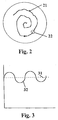
- FIG. 2 shows how a light spot 22 guided by this controlled movement 21 projects onto a diametrical surface at the end of the optical fiber of the deflection unit 5 .
- regulating the light spot 22 is at least approximately brought to the center of the optical fiber.
- Fig. 3 shows how the average intensity signal 31 on the detectors 10 and 11 has a superimposed modulation signal 32 when the fiber axis does not scan concentrically around the optical axis of the opto-mechanical system.
- the function of the controller 18 is to move the fine alignment mechanism 3, the end of the fiber 7, and / or the lens 4 such that this modulation signal 32 reaches a minimum value or the value zero.
- the device according to the invention works as follows:
- the light wave received by the optical receiving unit 2, 3 is focused via the fine alignment unit 3 and with the aid of the lens 4 approximately onto the center of the single-mode fiber 7 in the fiber mutator 5 when the control unit is at rest.
- a movement ( FIG. 2 ) of the light spot 22 about the center of the single-mode fiber 7 is effected by the fiber mutator 5 .
- the light spot 22 describes a high-frequency circular movement about the optical axis of the receiving optics.
- the end of the fiber 7 is moved by the nutator, one has at the end of the fiber, in the detectors 10 and 11 no spatial movement of the exiting light more.
- the rotational movement by means of the nutator 5 causes an intensity modulation ( FIG. 3 ) if the scanning movement does not take place exactly concentrically around the light spot.
- the high-frequency mechanical scanning movement of the fiber end caused by the deflection unit 5 can be controlled, for example, by means of a lateral displacement mechanism or by means of a bending element.
- Fast lateral shift units with small movements are known, for example, from optoelectronic readers such as CD players.
- bending elements can be easily realized from piezoceramic tubes with segmented electrodes. These tubes are firmly fixed only in one area, so that they can bend in the longitudinal direction by the piezoelectric effect. All mechanisms have in common that they are controlled via so-called IQ signals. After the IQ demodulation of the intensity signal is finally obtained the spatial error between the light spot 22 and the fiber axis.
- the error signal Sr causes via the controller 18 that the storage error is minimized.
- the relative offset between the intensity distribution of the Rx light in the focal plane of the lens 4 and the end of the fiber 7 generated by the rotational movement thus causes a temporally asymmetric intensity signal on the detectors 10 and 11, if the fiber axis is not concentric about the optical axis of the optomechanical Systems scans.
- the scanning point detector is thus, with very good approximation, replaced by the mode field of a monomode fiber.
- the scan radius should not exceed 1/10 of the mode field radius.
- the light wave is divided by the beam splitter into two nearly identical sub-beams, which are each supplied to one of the detectors 10 and 11 after the light of the local laser 12 has been coupled into the luminous flux via the optical fiber coupler 6 .
- two error component signals are generated, which are each implemented via a corresponding front-end transimpedance amplifier 15 and 16 in voltages Sa and Sb .
- the spatial error signal Sr is obtained by subtraction, and by sign-equitable addition of the error component signals Sa and Sb results in an output signal corresponding to the original data signal.
- the superposition of the local laser wave with the Rx-wave takes place only in the glass fiber, so that the spatial correlation degree between local laser and Rx field will be 1, that is, it is guaranteed streak-free overlay.
- the spatial correlation degree between local laser and Rx field will be 1, that is, it is guaranteed streak-free overlay.
- For optimization in the Adjustment or for a later optimization in the operation can then be guaranteed by one streak-free overlay and adjust to the absolute amplitude maximum.
- the optimal, that is streak-free adjustment state can then no longer the maximum intensity can be found alone.
- the level difference between the main maximum and one of the secondary maxima relatively small. It then exists always the latent danger that the tracking controller gets out of step and on one Secondary maximum of the intensity distribution controls what the linear control range then considerably restricts.
- the receiving fiber 7 which may be relatively long, it is possible to accommodate the receiver front-end (RFE), i.e. the detectors 10 , 11 and the amplifiers 15 , 16, at a relatively long distance from the optics.
- the optical fibers may be housed in a flexible protective cable or have a flexible sheath. The resulting heat in the RFE is thus optimally decoupled from the optics, and it no longer has to be reckoned with by the RFE induced thermal misalignments in the optical subsystem.
- the optical parts 2, 3, 4 and 5 can thus also be arranged at a relatively large distance from the data electronics and the RFE, which are located in the remote electronics unit.
- the device according to the present invention can advantageously replace the elements 16 and 26 of the optical bench according to the cited Offenlegungsschrift EP-0 844 473 A1 .
- the controller or computer controller 18 may be configured to cause movement of the movable end of the optical fiber 7 about the center of the focused point 22 of the information shaft 1 while the lens 4 is stationary.
- the controller 18 may cause movement of the lens 4 to move the focused light spot 22 of the information wave 1 about the center of the optical fiber 7 while the optical fiber is at rest.
- the device according to the present invention can be used for the same or similar purposes as in the mentioned patent application EP 0 831 604 A1 .
Landscapes
- Physics & Mathematics (AREA)
- Electromagnetism (AREA)
- Engineering & Computer Science (AREA)
- Computer Networks & Wireless Communication (AREA)
- Signal Processing (AREA)
- Astronomy & Astrophysics (AREA)
- General Physics & Mathematics (AREA)
- Optical Communication System (AREA)
- Optical Couplings Of Light Guides (AREA)
Claims (9)
- Procédé de génération d'un signal d'erreur avec un récepteur hétérodyne cohérent d'ondes lumineuses, de façon telle quecaractérisé en ce queune onde lumineuse d'informations (1) est amenée à un dispositif récepteur (2, 3, 4, 5) comportant un télescope récepteur,à l'onde lumineuse d'informations (1) est superposée de la lumière d'un laser local (12),l'onde lumineuse d'informations (1), après mélange de la lumière du laser local (12), est divisée par un séparateur de faisceau (6) en deux parties de faisceau,ces parties de faisceau sont respectivement amenées dans un détecteur (10, 11) pour générer le signal d'erreur,l'onde lumineuse d'informations (1) et la lumière du laser local (12) sont guidées par une fibre optique (7 ou 13) vers le séparateur de faisceau,les parties de faisceau sont guidées par respectivement une autre fibre optique (8, 9) vers les détecteurs (10, 11), etdans la zone de focalisation du dispositif de réception (2, 3, 4, 5), une unité de déflexion (5) agit, avec une face avant de la fibre optique (7),une extrémité de la fibre optique (7) est déplacée par l'unité de déflexion (5), oùpar ce déplacement de l'extrémité de la fibre optique (7), on entraíne le fait qu'un spot de focalisation (22) de l'onde lumineuse d'informations (1) est focalisé sur le centre de cette fibre optique (7), et oùle signal d'erreur (Sr) est couplé en retour à l'unité de réception (2, 3, 4, 5) et entraíne, via un régulateur, le fait que l'erreur d'écart est minimisée.
- Procédé selon la revendication 1, caractérisé en ce que l'onde lumineuse d'informations (1) est focalisée via une lentille (4) sur une surface avant au niveau de l'extrémité d'une fibre optique (7).
- Dispositif de génération d'un signal d'erreur lors de la réception hétérodyne cohérente d'ondes lumineuses, le dispositif se composant de :où le dispositif est exécuté de façon telle queune unité de réception opto-mécanique (2, 3, 4) comportant un télescope récepteur (2),un laser local (12),un séparateur de faisceau (6), etdeux détecteurs (10, 11),où l'unité de réception opto-mécanique (2, 3, 4) est disposée à l'opposé d'une face avant, au niveau de l'extrémité de la fibre optique (7), pour permettre une transmission de l'onde lumineuse d'informations (1) reçue via la fibre optique (7) vers le séparateur de faisceau (6), qui est relié par une autre fibre optique (13) au laser local (12) et par deux autres fibres optiques (8, 9) à un détecteur (10, 11) respectivement, pour générer un signal d'erreur (Sr),une onde lumineuse d'informations (1) est reçue avec le télescope récepteur (2),l'onde lumineuse d'informations (1) est superposée à la lumière d'un laser local (12),l'onde lumineuse d'informations (1), après le mélange de la lumière du laser local (12), est séparée via le séparateur de faisceau (6) en deux parties de faisceau qui sont respectivement amenées vers un détecteur (10, 11) pour générer le signal d'erreur (Sr),
caractérisé en ce que le dispositif est de plus exécuté de façon telle quel'onde lumineuse d'informations (1) et l'onde du laser local (12) sont amenées par les fibres optiques (7 ou 13) vers le séparateur de faisceau pour une répartition en deux parties de faisceau, qui sont ensuite amenées séparées respectivement par une des deux autres fibres optiques (8, 9), et quele signal d'erreur (Sr) est couplé en retour au niveau du dispositif récepteur pour que l'onde lumineuse reçue soit focalisée sur le centre de la fibre optique (7). - Dispositif selon la revendication 3, caractérisé en ce qu'il existe une unité de commande (14) qui agit sur cette face avant de la fibre optique (7) se trouvant dans la zone de focalisation du système optique de réception.
- Dispositif selon la revendication 3 ou 4, caractérisé en ce qu'il existe un régulateur (18) permettant de provoquer un déplacement de la fibre optique (7) autour du centre du point focalisé (22) de l'onde d'informations (1) et/ou un déplacement d'une lentille (4) de l'unité de réception opto-mécanique (2, 3, 4) de façon à ce que le point focalisé (22) de l'onde d'informations (1) soit projeté sur une zone de section centrale de la fibre optique (7).
- Dispositif selon l'une des revendications 3 à 5, caractérisé en ce qu'au moins une des fibres optiques (7, 8, 9, 13) est une fibre monomode à maintien de polarisation.
- Dispositif selon l'une des revendications 3 à 6, caractérisé en ce que le télescope récepteur (2) peut être focalisé sans occultation centrale.
- Dispositif selon l'une des revendications 3 à 7, caractérisé en ce que les fibres optiques (7, 8, 9, 13) sont dimensionnées et disposées de façon telle que l'on peut de ce fait éviter des lignes haute fréquence.
- Dispositif selon les revendications 4 et 5, caractérisé en ce que l'unité de commande (14) et le régulateur (18) sont disposés pour déplacer un dispositif de nutation de fibre (5) ou un déflecteur opto-électrique et/ou une lentille de focalisation à déplacement latéral (4).
Applications Claiming Priority (2)
| Application Number | Priority Date | Filing Date | Title |
|---|---|---|---|
| CH253298 | 1998-12-22 | ||
| CH253298 | 1998-12-22 |
Publications (2)
| Publication Number | Publication Date |
|---|---|
| EP1014604A1 EP1014604A1 (fr) | 2000-06-28 |
| EP1014604B1 true EP1014604B1 (fr) | 2005-06-22 |
Family
ID=4235925
Family Applications (1)
| Application Number | Title | Priority Date | Filing Date |
|---|---|---|---|
| EP99116491A Expired - Lifetime EP1014604B1 (fr) | 1998-12-22 | 1999-08-23 | Procédé et appareil pour la production d'un signal d'erreur en cas de réception hétérodyne cohérente des ondes lumineuses |
Country Status (6)
| Country | Link |
|---|---|
| US (1) | US6570695B1 (fr) |
| EP (1) | EP1014604B1 (fr) |
| JP (1) | JP2000196531A (fr) |
| AT (1) | ATE298478T1 (fr) |
| CA (1) | CA2282157A1 (fr) |
| DE (1) | DE59912199D1 (fr) |
Families Citing this family (7)
| Publication number | Priority date | Publication date | Assignee | Title |
|---|---|---|---|---|
| US20030035178A1 (en) * | 2001-08-17 | 2003-02-20 | George Seaver | Solid-state system for tracking and regulating optical beams |
| US8301032B2 (en) * | 2008-02-12 | 2012-10-30 | Arun Kumar Majumdar | Wide field-of-view amplified fiber-retro for secure high data rate communications and remote data transfer |
| DE102011113148B4 (de) * | 2011-09-14 | 2017-03-09 | Tesat-Spacecom Gmbh & Co.Kg | System zur Kommunikation zwischen zwei Kommunikationsplattformen nebst zugehöriger Gegenstände |
| US9813151B2 (en) | 2014-08-05 | 2017-11-07 | Massachusetts Institute Of Technology | Free-space optical communication module for small satellites |
| US10003402B2 (en) * | 2015-01-09 | 2018-06-19 | Massachusetts Institute Technology | Ground terminal design for high rate direct to earth optical communications |
| US10128949B2 (en) | 2015-02-27 | 2018-11-13 | Massachusetts Institute Of Technology | Methods, systems, and apparatus for global multiple-access optical communications |
| US11119218B2 (en) * | 2018-04-03 | 2021-09-14 | GM Global Technology Operations LLC | Coherent lidar system with extended field of view |
Family Cites Families (8)
| Publication number | Priority date | Publication date | Assignee | Title |
|---|---|---|---|---|
| FR2632075A1 (fr) * | 1988-05-31 | 1989-12-01 | Technomed Int Sa | Dispositif de transfert d'un rayon ou faisceau optique emis par un laser sur une fibre optique, et appareil de generation d'ondes de choc pour la destruction de cibles, notamment des tissus, des lithiases ou concretions, pourvu d'un tel dispositif |
| JPH0734080B2 (ja) * | 1988-10-20 | 1995-04-12 | 富士通株式会社 | コヒーレント光通信用ヘテロダイン検波受信装置 |
| US5062150A (en) * | 1989-01-23 | 1991-10-29 | Massachusetts Institute Of Technology | Fiber-based free-space optical system |
| US5252852A (en) * | 1989-03-14 | 1993-10-12 | Fujitsu Limited | Semiconductor device having flip chip bonding pads matched with pin photodiodes in a symmetrical layout configuration |
| US5808472A (en) * | 1996-09-17 | 1998-09-15 | Hughes Electronics Corporation | Apparatus and methods for positioning optical fibers and other resilient members |
| EP0831604B1 (fr) * | 1996-09-22 | 1999-07-21 | Oerlikon Contraves AG | Procédé et dispositif de contrÔle de position de deux ondes lumineuses en cas de réception hétérodyne cohérente |
| DE59700214D1 (de) * | 1996-11-25 | 1999-07-22 | Contraves Ag | Verfahren und Vorrichtung zur optischen Uebertragung von Daten über Freiraumstrecken |
| DE59801613D1 (de) * | 1997-12-21 | 2001-11-08 | Contraves Space Ag Zuerich | Vorrichtung zur gerichteten Abstrahlung und zum gerichteten Empfang modulierter Lichtwellen |
-
1999
- 1999-08-23 AT AT99116491T patent/ATE298478T1/de not_active IP Right Cessation
- 1999-08-23 EP EP99116491A patent/EP1014604B1/fr not_active Expired - Lifetime
- 1999-08-23 DE DE59912199T patent/DE59912199D1/de not_active Expired - Lifetime
- 1999-09-13 CA CA002282157A patent/CA2282157A1/fr not_active Abandoned
- 1999-10-05 US US09/410,961 patent/US6570695B1/en not_active Expired - Lifetime
- 1999-10-08 JP JP11287873A patent/JP2000196531A/ja active Pending
Also Published As
| Publication number | Publication date |
|---|---|
| EP1014604A1 (fr) | 2000-06-28 |
| CA2282157A1 (fr) | 2000-06-22 |
| DE59912199D1 (de) | 2005-07-28 |
| US6570695B1 (en) | 2003-05-27 |
| ATE298478T1 (de) | 2005-07-15 |
| JP2000196531A (ja) | 2000-07-14 |
Similar Documents
| Publication | Publication Date | Title |
|---|---|---|
| EP0154865B1 (fr) | Dispositif pour la correction d'alignement d'un faisceau laser passant un guide de lumière articulé | |
| EP3156838B1 (fr) | Tète de scanner et dispositif doté de tète de scanner | |
| EP3837779B1 (fr) | Structure de réception d'un signal de données optique | |
| DE3904752A1 (de) | Vorrichtung fuer den optischen direktempfang mehrerer wellenlaengen | |
| DE202018101626U1 (de) | MEMS-Lenkspiegel für Anwendungen in integrierten Photonikschaltungen | |
| DE3831839A1 (de) | Optischer sende- und/oder empfangsbaustein | |
| DE102019124598A1 (de) | Lidarsystem mit integriertem zirkulator | |
| EP0863628A1 (fr) | Méthode et dispositif pour l'opération d'un système d'émission à laser pour la communication optique dans l'espace libre | |
| DE69029600T2 (de) | Optische atmosphärische Übertragungsverbindung | |
| EP1014604B1 (fr) | Procédé et appareil pour la production d'un signal d'erreur en cas de réception hétérodyne cohérente des ondes lumineuses | |
| EP0992823A2 (fr) | Procédé de réglage d'un élément électrooptique et un tel élément | |
| WO1994017575A1 (fr) | Systeme laser fractal pilote en phase | |
| EP0831604B1 (fr) | Procédé et dispositif de contrÔle de position de deux ondes lumineuses en cas de réception hétérodyne cohérente | |
| EP1111816B1 (fr) | Méthode et dispositif d'établissement de connexion entre satellites | |
| WO1996006377A1 (fr) | Dispositif servant a injecter le faisceau lumineux d'un laser u.v. dans un microscope a balayage laser | |
| EP1378074B1 (fr) | Dispositif et systeme de transmission optique de donnees entre des satellites | |
| EP0400161A1 (fr) | Dispositif de couplage optique d'un module convertisseur électrooptique avec une fibre optique au moyen de deux lentilles | |
| DE19701155C1 (de) | Vorrichtung zum unterbrechungsfreien Auslenken eines Lichtstrahls | |
| DE102019124599B4 (de) | Verfahren zum erfassen eines objekts und lidarsystem | |
| DE102019213521A1 (de) | Aufbau zum Empfangen eines optischen Datensignals | |
| EP3379197B1 (fr) | Dispositif et procédé d'irradiation d'un objet | |
| DE102019124553A1 (de) | Chip-skaliertes lidar mit verbesserter reichweite | |
| WO2003081308A1 (fr) | Procede et dispositif d'epissurage de fibres optiques | |
| DE102019126476A1 (de) | Mehrfach photonen chip lidar systemarchitektur | |
| DE102019124601A1 (de) | Kohärente erkennung unter verwendung von backplane-emissionen |
Legal Events
| Date | Code | Title | Description |
|---|---|---|---|
| PUAI | Public reference made under article 153(3) epc to a published international application that has entered the european phase |
Free format text: ORIGINAL CODE: 0009012 |
|
| AK | Designated contracting states |
Kind code of ref document: A1 Designated state(s): AT BE CH CY DE DK ES FI FR GB GR IE IT LI LU MC NL PT SE |
|
| AX | Request for extension of the european patent |
Free format text: AL;LT;LV;MK;RO;SI |
|
| 17P | Request for examination filed |
Effective date: 20000731 |
|
| AKX | Designation fees paid |
Free format text: AT BE CH CY DE DK ES FI FR GB GR IE IT LI LU MC NL PT SE |
|
| 17Q | First examination report despatched |
Effective date: 20030812 |
|
| GRAP | Despatch of communication of intention to grant a patent |
Free format text: ORIGINAL CODE: EPIDOSNIGR1 |
|
| GRAS | Grant fee paid |
Free format text: ORIGINAL CODE: EPIDOSNIGR3 |
|
| GRAA | (expected) grant |
Free format text: ORIGINAL CODE: 0009210 |
|
| AK | Designated contracting states |
Kind code of ref document: B1 Designated state(s): AT BE CH CY DE DK ES FI FR GB GR IE IT LI LU MC NL PT SE |
|
| PG25 | Lapsed in a contracting state [announced via postgrant information from national office to epo] |
Ref country code: NL Free format text: LAPSE BECAUSE OF FAILURE TO SUBMIT A TRANSLATION OF THE DESCRIPTION OR TO PAY THE FEE WITHIN THE PRESCRIBED TIME-LIMIT Effective date: 20050622 Ref country code: IT Free format text: LAPSE BECAUSE OF FAILURE TO SUBMIT A TRANSLATION OF THE DESCRIPTION OR TO PAY THE FEE WITHIN THE PRESCRIBED TIME-LIMIT;WARNING: LAPSES OF ITALIAN PATENTS WITH EFFECTIVE DATE BEFORE 2007 MAY HAVE OCCURRED AT ANY TIME BEFORE 2007. THE CORRECT EFFECTIVE DATE MAY BE DIFFERENT FROM THE ONE RECORDED. Effective date: 20050622 Ref country code: IE Free format text: LAPSE BECAUSE OF FAILURE TO SUBMIT A TRANSLATION OF THE DESCRIPTION OR TO PAY THE FEE WITHIN THE PRESCRIBED TIME-LIMIT Effective date: 20050622 Ref country code: GB Free format text: LAPSE BECAUSE OF FAILURE TO SUBMIT A TRANSLATION OF THE DESCRIPTION OR TO PAY THE FEE WITHIN THE PRESCRIBED TIME-LIMIT Effective date: 20050622 Ref country code: FI Free format text: LAPSE BECAUSE OF FAILURE TO SUBMIT A TRANSLATION OF THE DESCRIPTION OR TO PAY THE FEE WITHIN THE PRESCRIBED TIME-LIMIT Effective date: 20050622 |
|
| REG | Reference to a national code |
Ref country code: GB Ref legal event code: FG4D Free format text: NOT ENGLISH |
|
| REG | Reference to a national code |
Ref country code: CH Ref legal event code: EP |
|
| REG | Reference to a national code |
Ref country code: IE Ref legal event code: FG4D Free format text: LANGUAGE OF EP DOCUMENT: GERMAN |
|
| REF | Corresponds to: |
Ref document number: 59912199 Country of ref document: DE Date of ref document: 20050728 Kind code of ref document: P |
|
| REG | Reference to a national code |
Ref country code: CH Ref legal event code: NV Representative=s name: OK PAT AG PATENTE MARKEN LIZENZEN |
|
| PG25 | Lapsed in a contracting state [announced via postgrant information from national office to epo] |
Ref country code: LU Free format text: LAPSE BECAUSE OF NON-PAYMENT OF DUE FEES Effective date: 20050823 Ref country code: CY Free format text: LAPSE BECAUSE OF FAILURE TO SUBMIT A TRANSLATION OF THE DESCRIPTION OR TO PAY THE FEE WITHIN THE PRESCRIBED TIME-LIMIT Effective date: 20050823 Ref country code: AT Free format text: LAPSE BECAUSE OF NON-PAYMENT OF DUE FEES Effective date: 20050823 |
|
| PG25 | Lapsed in a contracting state [announced via postgrant information from national office to epo] |
Ref country code: MC Free format text: LAPSE BECAUSE OF NON-PAYMENT OF DUE FEES Effective date: 20050831 Ref country code: BE Free format text: LAPSE BECAUSE OF NON-PAYMENT OF DUE FEES Effective date: 20050831 |
|
| PG25 | Lapsed in a contracting state [announced via postgrant information from national office to epo] |
Ref country code: SE Free format text: LAPSE BECAUSE OF FAILURE TO SUBMIT A TRANSLATION OF THE DESCRIPTION OR TO PAY THE FEE WITHIN THE PRESCRIBED TIME-LIMIT Effective date: 20050922 Ref country code: GR Free format text: LAPSE BECAUSE OF FAILURE TO SUBMIT A TRANSLATION OF THE DESCRIPTION OR TO PAY THE FEE WITHIN THE PRESCRIBED TIME-LIMIT Effective date: 20050922 Ref country code: DK Free format text: LAPSE BECAUSE OF FAILURE TO SUBMIT A TRANSLATION OF THE DESCRIPTION OR TO PAY THE FEE WITHIN THE PRESCRIBED TIME-LIMIT Effective date: 20050922 |
|
| PG25 | Lapsed in a contracting state [announced via postgrant information from national office to epo] |
Ref country code: ES Free format text: LAPSE BECAUSE OF FAILURE TO SUBMIT A TRANSLATION OF THE DESCRIPTION OR TO PAY THE FEE WITHIN THE PRESCRIBED TIME-LIMIT Effective date: 20051003 |
|
| PG25 | Lapsed in a contracting state [announced via postgrant information from national office to epo] |
Ref country code: PT Free format text: LAPSE BECAUSE OF FAILURE TO SUBMIT A TRANSLATION OF THE DESCRIPTION OR TO PAY THE FEE WITHIN THE PRESCRIBED TIME-LIMIT Effective date: 20051129 |
|
| NLV1 | Nl: lapsed or annulled due to failure to fulfill the requirements of art. 29p and 29m of the patents act | ||
| GBV | Gb: ep patent (uk) treated as always having been void in accordance with gb section 77(7)/1977 [no translation filed] |
Effective date: 20050622 |
|
| REG | Reference to a national code |
Ref country code: IE Ref legal event code: FD4D |
|
| ET | Fr: translation filed | ||
| PLBE | No opposition filed within time limit |
Free format text: ORIGINAL CODE: 0009261 |
|
| STAA | Information on the status of an ep patent application or granted ep patent |
Free format text: STATUS: NO OPPOSITION FILED WITHIN TIME LIMIT |
|
| 26N | No opposition filed |
Effective date: 20060323 |
|
| REG | Reference to a national code |
Ref country code: CH Ref legal event code: PFA Owner name: OERLIKON SPACE AG Free format text: CONTRAVES SPACE AG#SCHAFFHAUSERSTRASSE 580#8052 ZUERICH (CH) -TRANSFER TO- OERLIKON SPACE AG#SCHAFFHAUSERSTRASSE 580#8052 ZUERICH (CH) |
|
| REG | Reference to a national code |
Ref country code: FR Ref legal event code: CD |
|
| BERE | Be: lapsed |
Owner name: CONTRAVES SPACE A.G. Effective date: 20050831 |
|
| REG | Reference to a national code |
Ref country code: FR Ref legal event code: PLFP Year of fee payment: 18 |
|
| REG | Reference to a national code |
Ref country code: DE Ref legal event code: R082 Ref document number: 59912199 Country of ref document: DE Representative=s name: RACH, WERNER, DIPL.-CHEM. DR.RER.NAT., DE Ref country code: DE Ref legal event code: R081 Ref document number: 59912199 Country of ref document: DE Owner name: OEI OPTO AG, CH Free format text: FORMER OWNER: OERLIKON SPACE AG, ZUERICH, CH |
|
| REG | Reference to a national code |
Ref country code: CH Ref legal event code: PUE Owner name: OEI OPTO AG, CH Free format text: FORMER OWNER: OERLIKON SPACE AG, CH |
|
| PGFP | Annual fee paid to national office [announced via postgrant information from national office to epo] |
Ref country code: DE Payment date: 20160816 Year of fee payment: 18 Ref country code: CH Payment date: 20160812 Year of fee payment: 18 |
|
| PGFP | Annual fee paid to national office [announced via postgrant information from national office to epo] |
Ref country code: FR Payment date: 20160712 Year of fee payment: 18 |
|
| REG | Reference to a national code |
Ref country code: FR Ref legal event code: TP Owner name: OEI OPTO AG, CH Effective date: 20161104 Ref country code: FR Ref legal event code: CD Owner name: OEI OPTO AG, CH Effective date: 20161104 |
|
| REG | Reference to a national code |
Ref country code: CH Ref legal event code: NV Representative=s name: TROESCH SCHEIDEGGER WERNER AG, CH |
|
| REG | Reference to a national code |
Ref country code: DE Ref legal event code: R119 Ref document number: 59912199 Country of ref document: DE |
|
| REG | Reference to a national code |
Ref country code: CH Ref legal event code: PL |
|
| PG25 | Lapsed in a contracting state [announced via postgrant information from national office to epo] |
Ref country code: CH Free format text: LAPSE BECAUSE OF NON-PAYMENT OF DUE FEES Effective date: 20170831 Ref country code: LI Free format text: LAPSE BECAUSE OF NON-PAYMENT OF DUE FEES Effective date: 20170831 |
|
| REG | Reference to a national code |
Ref country code: FR Ref legal event code: ST Effective date: 20180430 |
|
| PG25 | Lapsed in a contracting state [announced via postgrant information from national office to epo] |
Ref country code: DE Free format text: LAPSE BECAUSE OF NON-PAYMENT OF DUE FEES Effective date: 20180301 |
|
| PG25 | Lapsed in a contracting state [announced via postgrant information from national office to epo] |
Ref country code: FR Free format text: LAPSE BECAUSE OF NON-PAYMENT OF DUE FEES Effective date: 20170831 |