EP1014655A2 - Anordnung zur Unterdrückung von akustischen Reflexionen bei Handapparaten der Fernsprechtechnik - Google Patents
Anordnung zur Unterdrückung von akustischen Reflexionen bei Handapparaten der Fernsprechtechnik Download PDFInfo
- Publication number
- EP1014655A2 EP1014655A2 EP99117660A EP99117660A EP1014655A2 EP 1014655 A2 EP1014655 A2 EP 1014655A2 EP 99117660 A EP99117660 A EP 99117660A EP 99117660 A EP99117660 A EP 99117660A EP 1014655 A2 EP1014655 A2 EP 1014655A2
- Authority
- EP
- European Patent Office
- Prior art keywords
- handset
- earpiece
- housing
- channel
- arrangement
- Prior art date
- Legal status (The legal status is an assumption and is not a legal conclusion. Google has not performed a legal analysis and makes no representation as to the accuracy of the status listed.)
- Granted
Links
Images


Classifications
-
- H—ELECTRICITY
- H04—ELECTRIC COMMUNICATION TECHNIQUE
- H04M—TELEPHONIC COMMUNICATION
- H04M1/00—Substation equipment, e.g. for use by subscribers
- H04M1/02—Constructional features of telephone sets
- H04M1/03—Constructional features of telephone transmitters or receivers, e.g. telephone hand-sets
- H04M1/035—Improving the acoustic characteristics by means of constructional features of the housing, e.g. ribs, walls, resonating chambers or cavities
-
- H—ELECTRICITY
- H04—ELECTRIC COMMUNICATION TECHNIQUE
- H04R—LOUDSPEAKERS, MICROPHONES, GRAMOPHONE PICK-UPS OR LIKE ACOUSTIC ELECTROMECHANICAL TRANSDUCERS; ELECTRIC HEARING AIDS; PUBLIC ADDRESS SYSTEMS
- H04R1/00—Details of transducers, loudspeakers or microphones
- H04R1/20—Arrangements for obtaining desired frequency or directional characteristics
- H04R1/22—Arrangements for obtaining desired frequency or directional characteristics for obtaining desired frequency characteristic only
- H04R1/28—Transducer mountings or enclosures modified by provision of mechanical or acoustic impedances, e.g. resonator, damping means
- H04R1/2869—Reduction of undesired resonances, i.e. standing waves within enclosure, or of undesired vibrations, i.e. of the enclosure itself
- H04R1/2884—Reduction of undesired resonances, i.e. standing waves within enclosure, or of undesired vibrations, i.e. of the enclosure itself by means of the enclosure structure, i.e. strengthening or shape of the enclosure
- H04R1/2888—Reduction of undesired resonances, i.e. standing waves within enclosure, or of undesired vibrations, i.e. of the enclosure itself by means of the enclosure structure, i.e. strengthening or shape of the enclosure for loudspeaker transducers
Definitions
- the invention relates to an arrangement for suppressing acoustic reflections in handsets of telephone technology.
- Figure 5 shows a first known solution in which in a handset 1 with an existing housing leak 7 a microphone 4 and a sealed earpiece 5 is installed.
- the soundproof earpiece 5 is sealed with the Handset housing connected, and due to a tight The back does not emit any direct sound into the handset housing emitted.
- FIG. 6 A second possible solution is shown in which an open earpiece by means of an earpiece with a certain volume soundproof from the inside the handset is shielded, so that no or less Sound can escape into the handset housing.
- FIG. 1 A third possible solution is shown in FIG the in the handset 1 an open backward earphone 8 is installed, but at the same time the microphone 4 with a Microphone capsule 10 opposite the interior of the handset is shielded and in addition the housing leakage 7 is sealed by means of a housing seal 11.
- the sealing of the microphone and the handset housing there can be no or less sound on the inside of the receiver to the microphone arrive and no or less sound through opening radiated from the phone housing towards the microphone become.
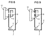
- Figures 8 and 9 show possible solutions with regard to better radiation of low frequencies through the use of acoustics low-impedance earpiece principles. Need this a defined back volume and certain leak elements.
- Transducers with increased depth radiation are used. By the integration of an artificial leak gap between the earpiece and ear this cant is reduced so that again gives an even frequency response. In practice leaks between the phone housing and the ear then change the acoustic radiation of the telephone handset only marginally, the emission of the low frequencies preserved.
- the prerequisite for the reinforced Deep radiation from the transducer is an opening in the back of the earpiece, d. H. an opening of the volume on the back of the membrane. This applies particularly to the downsizing of the Earpiece dimensions.
- Figures 8 and 9 show the leak gap 13, which in Figure 8 is generated in that the earpiece is not directly inside is attached to the handset housing wall, and in Figure 9 is achieved in that below the earphone 8 in the Housing wall an opening within the contact surface of the ear 12, which is a circle with a diameter of 25 mm which contains the sound outlet of the earpiece becomes.
- the opening on the back of the earpiece is contrary the above-mentioned problem regarding the low acoustic Attenuation because it leads to sound radiation from the back of the membrane into the interior of the handset.
- the sound pressure within the handset housing reaches free therefore partly higher values than on the outside of the earpiece.
- the object of the present invention is an arrangement of the Specify the type mentioned, in which the low impedance Earpiece principles can be applied, but which at the same time there is a large acoustic attenuation between the earpiece and microphone reached.
- the acoustically low-impedance integration is possible without sound being emitted into the inside of the handset.
- the channel according to the invention is neither within the Earpiece still a special one within the handset Back volume necessary for increased depth radiation.
- the earpiece has one infinitely large back volume and can therefore emphasize depth Radiate even with smaller earbuds.
- An expedient development of the invention is characterized in that that the channel emerges from the top of the handset. This is particularly favorable for good acoustic Attenuation between earpiece and microphone.
- Another expedient embodiment of the present invention is characterized in that an acoustically low impedance Structure is provided, being within the bearing surface of the ear, which is a circle with a diameter of 25 mm, which forms the sound outlet of the earpiece contains a leak opening in the housing wall of the handset is provided, the space behind the leak opening connected to the canal interior while facing it the rest of the interior of the handset is sealed.
- Figures 1 to 4 show exemplary embodiments of the invention Handsets.
- Figure 1 shows a handset 3 according to the invention, in which the rear volume of the earpiece 16 over a sealed channel 17 with the external volume of the handset 3 is connected. It is particularly advantageous if the Channel 17 exits on the top of the handset.
- FIG 2 shows an embodiment according to the present Invention in which the acoustic low impedance structure is applied. That means the front of the earpiece must be acoustically connected to the back, the ear and the front of the earphone does not form a complete seal allowed to.
- the handset 14 of Figure 2 in turn has one Earpiece 16 with a channel 17, the earpiece being spaced apart arranged to the inside of the housing with the sound outlet 18 is.
- the handset in Figure 2 via a leak opening 19 which defines the external volume of the handset 14 connects to the interior of the handset 14.
- FIG 3 shows another embodiment in which a handset 15 with a leak opening 20 within the Contact surface of the ear 12, which is a circle with a Diameter of 25 mm, which forms the sound outlet 18 the earpiece 16 contains.
- This leak opening 20 is with a Housing volume part connected, which with the channel interior connected while it is opposite the rest of the case interior the handset 15 is shielded.
- Figure 4 shows a further embodiment of the invention Handset at which flow 21, which as Protective covers on the earpiece serve specifically as acoustic Impedances for tuning the acoustic frequency response and the leakage behavior can be used.
- the diaphragm back volume as well as the channel volume can resonators for tuning the acoustic radiation and the leakage behavior will be realized.
Landscapes
- Physics & Mathematics (AREA)
- Engineering & Computer Science (AREA)
- Acoustics & Sound (AREA)
- Signal Processing (AREA)
- Health & Medical Sciences (AREA)
- Otolaryngology (AREA)
- Telephone Set Structure (AREA)
Abstract
Zur Verbesserung des akustischen Verhaltens ist ein gegenüber dem Gehäuseinneren abgedichteter Kanal vorgesehen, der das rückwärtige Raumvolumen der Hörkapsel mit dem Außenvolumen des Handapparates verbindet, wobei der Kanal außerhalb der eigentlichen Hörmuschel austritt.
Description
Claims (4)
- Anordnung zur Unterdrückung von akustischen Reflexionen bei Handapparaten der Fernsprechtechnik,
dadurch gekennzeichnet,
daß ein gegenüber dem Gehäuseinneren abgedichteter Kanal (17) das rückwärtige Raumvolumen der Hörkapsel (16) mit dem Außenvolumen des Handapparates (3) verbindet, wobei der Kanal (17) außerhalb der eigentlichen Hörmuschel austritt. - Anordnung nach Anspruch 1,
dadurch gekennzeichnet,
daß der Kanal (17) an der Handapparateoberseite austritt. - Anordnung nach Anspruch 1 oder 2,
dadurch gekennzeichnet,
daß ein akustisch niederimpedanter Aufbau vorgesehen ist, bei dem innerhalb der Auflagefläche des Ohres (12), welche einen Kreis mit einem Durchmesser von 25 mm bildet, welcher den Schallaustritt der Hörkapsel (16) enthält, in der Gehäusewand des Handapparates eine mit dem Gehäuseinneren verbundene Lecköffnung (19) vorgesehen ist. - Anordnung nach Anspruch 1 oder 2,
dadurch gekennzeichnet,
daß ein akustisch niederimpedanter Aufbau vorgesehen ist, bei dem innerhalb der Auflagefläche des Ohres (12), welche einen Kreis mit einem Durchmesser von 25 mm bildet, welcher den Schallaustritt der Hörkapsel (16) enthält, in der Gehäusewand des Handapparates (15) eine Lecköffnung (20) vorgesehen ist, wobei der Raum hinter der Lecköffnung (20) mit dem Kanalinnenraum (17) verbunden ist, während er gegenüber dem übrigen Gehäuseinneren des Handapparates (15) abgedichtet ist.
Applications Claiming Priority (2)
| Application Number | Priority Date | Filing Date | Title |
|---|---|---|---|
| DE19840827 | 1998-09-07 | ||
| DE19840827 | 1998-09-07 |
Publications (3)
| Publication Number | Publication Date |
|---|---|
| EP1014655A2 true EP1014655A2 (de) | 2000-06-28 |
| EP1014655A3 EP1014655A3 (de) | 2003-04-16 |
| EP1014655B1 EP1014655B1 (de) | 2005-06-08 |
Family
ID=7880116
Family Applications (1)
| Application Number | Title | Priority Date | Filing Date |
|---|---|---|---|
| EP99117660A Expired - Lifetime EP1014655B1 (de) | 1998-09-07 | 1999-09-07 | Anordnung zur Unterdrückung von akustischen Reflexionen bei Handapparaten der Fernsprechtechnik |
Country Status (5)
| Country | Link |
|---|---|
| EP (1) | EP1014655B1 (de) |
| CN (1) | CN1156129C (de) |
| AT (1) | ATE297630T1 (de) |
| DE (1) | DE59912150D1 (de) |
| ES (1) | ES2239820T3 (de) |
Cited By (1)
| Publication number | Priority date | Publication date | Assignee | Title |
|---|---|---|---|---|
| CN112615950A (zh) * | 2020-12-18 | 2021-04-06 | 维沃移动通信有限公司 | 电子设备 |
Families Citing this family (1)
| Publication number | Priority date | Publication date | Assignee | Title |
|---|---|---|---|---|
| CN111464680B (zh) * | 2020-04-09 | 2021-07-16 | Oppo广东移动通信有限公司 | 电子设备 |
Family Cites Families (3)
| Publication number | Priority date | Publication date | Assignee | Title |
|---|---|---|---|---|
| CA2169641C (en) * | 1993-08-18 | 2004-01-20 | Telefonaktiebolaget Lm Ericsson | Telephone handset |
| US5729605A (en) * | 1995-06-19 | 1998-03-17 | Plantronics, Inc. | Headset with user adjustable frequency response |
| DE19526810A1 (de) * | 1995-07-12 | 1997-01-16 | Deutsche Telephonwerk Kabel | Anordnung für Höreinrichtungen in Kommunikations-Endgeräten |
-
1999
- 1999-09-07 DE DE59912150T patent/DE59912150D1/de not_active Expired - Fee Related
- 1999-09-07 AT AT99117660T patent/ATE297630T1/de active
- 1999-09-07 ES ES99117660T patent/ES2239820T3/es not_active Expired - Lifetime
- 1999-09-07 EP EP99117660A patent/EP1014655B1/de not_active Expired - Lifetime
- 1999-09-07 CN CNB991197879A patent/CN1156129C/zh not_active Expired - Fee Related
Cited By (1)
| Publication number | Priority date | Publication date | Assignee | Title |
|---|---|---|---|---|
| CN112615950A (zh) * | 2020-12-18 | 2021-04-06 | 维沃移动通信有限公司 | 电子设备 |
Also Published As
| Publication number | Publication date |
|---|---|
| EP1014655A3 (de) | 2003-04-16 |
| DE59912150D1 (de) | 2005-07-14 |
| EP1014655B1 (de) | 2005-06-08 |
| CN1247429A (zh) | 2000-03-15 |
| ES2239820T3 (es) | 2005-10-01 |
| ATE297630T1 (de) | 2005-06-15 |
| CN1156129C (zh) | 2004-06-30 |
Similar Documents
| Publication | Publication Date | Title |
|---|---|---|
| DE102012224406B4 (de) | Ohrhörer mit einer Umhausung des offenen/geschlossenen Typs | |
| DE60026562T2 (de) | Elektroakustische kommunikationseinheit | |
| DE60226003T2 (de) | Steuerung der rückhörunterdrückung in einem telekommunikationsinstrument | |
| DE102018221726A1 (de) | Audiovorrichtung mit akustischem Ventil | |
| DE2261122A1 (de) | Hoerteil eines fernsprechhandapparates | |
| EP3772860A1 (de) | Mobiltelefon mit einem eine rückseitige sekundäröffnung aufweisenden audiosystem | |
| EP1349425B1 (de) | Platzierung eines elektroakustischen Miniaturwandlers in einem Hörgerät | |
| DE102010004667A1 (de) | Gehäuse und Lautsprechermodul | |
| EP0493361B1 (de) | Als Richtmikrophon ausgebildeter Telephonhandapparat | |
| DE69737204T2 (de) | Telefonhandapparat, schnurloses telefon oder mobiltelefon | |
| EP1014655B1 (de) | Anordnung zur Unterdrückung von akustischen Reflexionen bei Handapparaten der Fernsprechtechnik | |
| DE19640412C1 (de) | Kommunikationsendgerät | |
| DE4010372A1 (de) | Hoergeraet mit ohrpassstueck | |
| WO2018234132A1 (de) | In-ohr hörer | |
| WO2000049789A1 (de) | Handapparat für die fernsprechtechnik | |
| WO2000060830A2 (de) | Mobiltelefon | |
| DE930268C (de) | Vorrichtung an der Einsprache von Fernsprechapparaten zur Verhinderung des Mithoerens | |
| DE29919581U1 (de) | Freisprecheinrichtung für Handys in Autos | |
| EP0496235B1 (de) | Handapparat für Telefone | |
| DE10028690C2 (de) | Mikrofoneinsprache, insbesondere für einen Telefonhörer | |
| EP0499674A1 (de) | Anordnung zur Unterdrückung von akustischen Reflexionen bei Handapparaten der Fernsprechtechnik | |
| DE822251C (de) | Abgeschirmtes Mikrofon | |
| DE9419476U1 (de) | Mittels eines Meßkopplers abgestimmter elektroakustischer Wandler | |
| EP0490215A2 (de) | Fernsprechgerät mit Freisprecheinrichtung | |
| EP4106347A1 (de) | Hörvorrichtung |
Legal Events
| Date | Code | Title | Description |
|---|---|---|---|
| PUAI | Public reference made under article 153(3) epc to a published international application that has entered the european phase |
Free format text: ORIGINAL CODE: 0009012 |
|
| AK | Designated contracting states |
Kind code of ref document: A2 Designated state(s): AT BE CH CY DE DK ES FI FR GB GR IE IT LI LU MC NL PT SE |
|
| AX | Request for extension of the european patent |
Free format text: AL;LT;LV;MK;RO;SI |
|
| PUAL | Search report despatched |
Free format text: ORIGINAL CODE: 0009013 |
|
| AK | Designated contracting states |
Designated state(s): AT BE CH CY DE DK ES FI FR GB GR IE IT LI LU MC NL PT SE |
|
| AX | Request for extension of the european patent |
Extension state: AL LT LV MK RO SI |
|
| RIC1 | Information provided on ipc code assigned before grant |
Ipc: 7H 04R 1/38 B Ipc: 7H 04M 1/20 A |
|
| 17P | Request for examination filed |
Effective date: 20031015 |
|
| 17Q | First examination report despatched |
Effective date: 20031118 |
|
| AKX | Designation fees paid |
Designated state(s): AT BE CH CY DE DK ES FI FR GB GR IE IT LI LU MC NL PT SE |
|
| GRAP | Despatch of communication of intention to grant a patent |
Free format text: ORIGINAL CODE: EPIDOSNIGR1 |
|
| GRAS | Grant fee paid |
Free format text: ORIGINAL CODE: EPIDOSNIGR3 |
|
| GRAA | (expected) grant |
Free format text: ORIGINAL CODE: 0009210 |
|
| AK | Designated contracting states |
Kind code of ref document: B1 Designated state(s): AT BE CH CY DE DK ES FI FR GB GR IE IT LI LU MC NL PT SE |
|
| PG25 | Lapsed in a contracting state [announced via postgrant information from national office to epo] |
Ref country code: IE Free format text: LAPSE BECAUSE OF FAILURE TO SUBMIT A TRANSLATION OF THE DESCRIPTION OR TO PAY THE FEE WITHIN THE PRESCRIBED TIME-LIMIT Effective date: 20050608 |
|
| REG | Reference to a national code |
Ref country code: GB Ref legal event code: FG4D Free format text: NOT ENGLISH |
|
| REG | Reference to a national code |
Ref country code: CH Ref legal event code: NV Representative=s name: SIEMENS SCHWEIZ AG Ref country code: CH Ref legal event code: EP |
|
| GBT | Gb: translation of ep patent filed (gb section 77(6)(a)/1977) |
Effective date: 20050608 |
|
| REF | Corresponds to: |
Ref document number: 59912150 Country of ref document: DE Date of ref document: 20050714 Kind code of ref document: P |
|
| REG | Reference to a national code |
Ref country code: SE Ref legal event code: TRGR |
|
| REG | Reference to a national code |
Ref country code: IE Ref legal event code: FG4D Free format text: LANGUAGE OF EP DOCUMENT: GERMAN |
|
| PG25 | Lapsed in a contracting state [announced via postgrant information from national office to epo] |
Ref country code: CY Free format text: LAPSE BECAUSE OF FAILURE TO SUBMIT A TRANSLATION OF THE DESCRIPTION OR TO PAY THE FEE WITHIN THE PRESCRIBED TIME-LIMIT Effective date: 20050907 |
|
| PG25 | Lapsed in a contracting state [announced via postgrant information from national office to epo] |
Ref country code: GR Free format text: LAPSE BECAUSE OF FAILURE TO SUBMIT A TRANSLATION OF THE DESCRIPTION OR TO PAY THE FEE WITHIN THE PRESCRIBED TIME-LIMIT Effective date: 20050908 Ref country code: DK Free format text: LAPSE BECAUSE OF FAILURE TO SUBMIT A TRANSLATION OF THE DESCRIPTION OR TO PAY THE FEE WITHIN THE PRESCRIBED TIME-LIMIT Effective date: 20050908 |
|
| PG25 | Lapsed in a contracting state [announced via postgrant information from national office to epo] |
Ref country code: MC Free format text: LAPSE BECAUSE OF NON-PAYMENT OF DUE FEES Effective date: 20050930 Ref country code: LU Free format text: LAPSE BECAUSE OF NON-PAYMENT OF DUE FEES Effective date: 20050930 |
|
| REG | Reference to a national code |
Ref country code: ES Ref legal event code: FG2A Ref document number: 2239820 Country of ref document: ES Kind code of ref document: T3 |
|
| PG25 | Lapsed in a contracting state [announced via postgrant information from national office to epo] |
Ref country code: PT Free format text: LAPSE BECAUSE OF FAILURE TO SUBMIT A TRANSLATION OF THE DESCRIPTION OR TO PAY THE FEE WITHIN THE PRESCRIBED TIME-LIMIT Effective date: 20051114 |
|
| REG | Reference to a national code |
Ref country code: IE Ref legal event code: FD4D |
|
| ET | Fr: translation filed | ||
| PLBE | No opposition filed within time limit |
Free format text: ORIGINAL CODE: 0009261 |
|
| STAA | Information on the status of an ep patent application or granted ep patent |
Free format text: STATUS: NO OPPOSITION FILED WITHIN TIME LIMIT |
|
| 26N | No opposition filed |
Effective date: 20060309 |
|
| REG | Reference to a national code |
Ref country code: CH Ref legal event code: PUE Owner name: BENQ MOBILE GMBH & CO.KG Free format text: SIEMENS AKTIENGESELLSCHAFT#WITTELSBACHERPLATZ 2#80333 MUENCHEN (DE) -TRANSFER TO- BENQ MOBILE GMBH & CO.KG#HAIDENAUPLATZ 1#81667 MUENCHEN (DE) |
|
| REG | Reference to a national code |
Ref country code: GB Ref legal event code: 732E |
|
| NLS | Nl: assignments of ep-patents |
Owner name: BENQ MOBILE GMBH & CO. OHG Effective date: 20060914 |
|
| REG | Reference to a national code |
Ref country code: FR Ref legal event code: TP |
|
| REG | Reference to a national code |
Ref country code: GB Ref legal event code: 732E |
|
| PGFP | Annual fee paid to national office [announced via postgrant information from national office to epo] |
Ref country code: FI Payment date: 20070808 Year of fee payment: 9 |
|
| BECA | Be: change of holder's address |
Owner name: *BENQ MOBILE G.M.B.H. & CO. OHGHAIDENAUPLATZ 1, D- Effective date: 20050608 |
|
| BECH | Be: change of holder |
Owner name: *BENQ MOBILE G.M.B.H. & CO. OHG Effective date: 20050608 |
|
| PGFP | Annual fee paid to national office [announced via postgrant information from national office to epo] |
Ref country code: GB Payment date: 20070910 Year of fee payment: 9 |
|
| PGFP | Annual fee paid to national office [announced via postgrant information from national office to epo] |
Ref country code: SE Payment date: 20070906 Year of fee payment: 9 Ref country code: NL Payment date: 20070913 Year of fee payment: 9 Ref country code: IT Payment date: 20070926 Year of fee payment: 9 Ref country code: BE Payment date: 20070918 Year of fee payment: 9 |
|
| PGFP | Annual fee paid to national office [announced via postgrant information from national office to epo] |
Ref country code: FR Payment date: 20070918 Year of fee payment: 9 Ref country code: CH Payment date: 20080331 Year of fee payment: 9 |
|
| BERE | Be: lapsed |
Owner name: *BENQ MOBILE G.M.B.H. & CO. OHG Effective date: 20080930 |
|
| REG | Reference to a national code |
Ref country code: CH Ref legal event code: PCAR Free format text: SIEMENS SCHWEIZ AG;INTELLECTUAL PROPERTY FREILAGERSTRASSE 40;8047 ZUERICH (CH) |
|
| PG25 | Lapsed in a contracting state [announced via postgrant information from national office to epo] |
Ref country code: DE Free format text: LAPSE BECAUSE OF NON-PAYMENT OF DUE FEES Effective date: 20080401 |
|
| REG | Reference to a national code |
Ref country code: CH Ref legal event code: PL |
|
| GBPC | Gb: european patent ceased through non-payment of renewal fee |
Effective date: 20080907 |
|
| PG25 | Lapsed in a contracting state [announced via postgrant information from national office to epo] |
Ref country code: NL Free format text: LAPSE BECAUSE OF NON-PAYMENT OF DUE FEES Effective date: 20090401 Ref country code: FI Free format text: LAPSE BECAUSE OF NON-PAYMENT OF DUE FEES Effective date: 20080907 |
|
| NLV4 | Nl: lapsed or anulled due to non-payment of the annual fee |
Effective date: 20090401 |
|
| REG | Reference to a national code |
Ref country code: FR Ref legal event code: ST Effective date: 20090529 |
|
| PG25 | Lapsed in a contracting state [announced via postgrant information from national office to epo] |
Ref country code: BE Free format text: LAPSE BECAUSE OF NON-PAYMENT OF DUE FEES Effective date: 20080930 |
|
| PG25 | Lapsed in a contracting state [announced via postgrant information from national office to epo] |
Ref country code: IT Free format text: LAPSE BECAUSE OF NON-PAYMENT OF DUE FEES Effective date: 20080907 |
|
| PG25 | Lapsed in a contracting state [announced via postgrant information from national office to epo] |
Ref country code: LI Free format text: LAPSE BECAUSE OF NON-PAYMENT OF DUE FEES Effective date: 20080930 Ref country code: FR Free format text: LAPSE BECAUSE OF NON-PAYMENT OF DUE FEES Effective date: 20080930 Ref country code: CH Free format text: LAPSE BECAUSE OF NON-PAYMENT OF DUE FEES Effective date: 20080930 |
|
| PGRI | Patent reinstated in contracting state [announced from national office to epo] |
Ref country code: DE Effective date: 20090720 |
|
| PG25 | Lapsed in a contracting state [announced via postgrant information from national office to epo] |
Ref country code: GB Free format text: LAPSE BECAUSE OF NON-PAYMENT OF DUE FEES Effective date: 20080907 |
|
| PGFP | Annual fee paid to national office [announced via postgrant information from national office to epo] |
Ref country code: DE Payment date: 20090527 Year of fee payment: 10 |
|
| PG25 | Lapsed in a contracting state [announced via postgrant information from national office to epo] |
Ref country code: SE Free format text: LAPSE BECAUSE OF NON-PAYMENT OF DUE FEES Effective date: 20080908 Ref country code: DE Free format text: LAPSE BECAUSE OF NON-PAYMENT OF DUE FEES Effective date: 20100401 |
|
| PGFP | Annual fee paid to national office [announced via postgrant information from national office to epo] |
Ref country code: AT Payment date: 20120829 Year of fee payment: 14 |
|
| PGFP | Annual fee paid to national office [announced via postgrant information from national office to epo] |
Ref country code: ES Payment date: 20130813 Year of fee payment: 15 |
|
| REG | Reference to a national code |
Ref country code: AT Ref legal event code: MM01 Ref document number: 297630 Country of ref document: AT Kind code of ref document: T Effective date: 20130907 |
|
| PG25 | Lapsed in a contracting state [announced via postgrant information from national office to epo] |
Ref country code: AT Free format text: LAPSE BECAUSE OF NON-PAYMENT OF DUE FEES Effective date: 20130907 |
|
| REG | Reference to a national code |
Ref country code: ES Ref legal event code: FD2A Effective date: 20160303 |
|
| PG25 | Lapsed in a contracting state [announced via postgrant information from national office to epo] |
Ref country code: ES Free format text: LAPSE BECAUSE OF NON-PAYMENT OF DUE FEES Effective date: 20140908 |