EP1014754A2 - Matrice de commutation pour applications de télécommunications - Google Patents
Matrice de commutation pour applications de télécommunications Download PDFInfo
- Publication number
- EP1014754A2 EP1014754A2 EP19990440363 EP99440363A EP1014754A2 EP 1014754 A2 EP1014754 A2 EP 1014754A2 EP 19990440363 EP19990440363 EP 19990440363 EP 99440363 A EP99440363 A EP 99440363A EP 1014754 A2 EP1014754 A2 EP 1014754A2
- Authority
- EP
- European Patent Office
- Prior art keywords
- path
- matrix
- reached
- switching
- column
- Prior art date
- Legal status (The legal status is an assumption and is not a legal conclusion. Google has not performed a legal analysis and makes no representation as to the accuracy of the status listed.)
- Withdrawn
Links
- 239000011159 matrix material Substances 0.000 title claims description 169
- 238000000034 method Methods 0.000 claims description 24
- 230000005540 biological transmission Effects 0.000 description 4
- 241001212149 Cathetus Species 0.000 description 1
- 208000008589 Obesity Diseases 0.000 description 1
- 230000002457 bidirectional effect Effects 0.000 description 1
- 230000000903 blocking effect Effects 0.000 description 1
- 238000004519 manufacturing process Methods 0.000 description 1
- 235000020824 obesity Nutrition 0.000 description 1
- 238000010187 selection method Methods 0.000 description 1
Images

Classifications
-
- H—ELECTRICITY
- H04—ELECTRIC COMMUNICATION TECHNIQUE
- H04Q—SELECTING
- H04Q11/00—Selecting arrangements for multiplex systems
- H04Q11/04—Selecting arrangements for multiplex systems for time-division multiplexing
-
- H—ELECTRICITY
- H04—ELECTRIC COMMUNICATION TECHNIQUE
- H04Q—SELECTING
- H04Q2213/00—Indexing scheme relating to selecting arrangements in general and for multiplex systems
- H04Q2213/1302—Relay switches
-
- H—ELECTRICITY
- H04—ELECTRIC COMMUNICATION TECHNIQUE
- H04Q—SELECTING
- H04Q2213/00—Indexing scheme relating to selecting arrangements in general and for multiplex systems
- H04Q2213/1304—Coordinate switches, crossbar, 4/2 with relays, coupling field
-
- H—ELECTRICITY
- H04—ELECTRIC COMMUNICATION TECHNIQUE
- H04Q—SELECTING
- H04Q2213/00—Indexing scheme relating to selecting arrangements in general and for multiplex systems
- H04Q2213/13076—Distributing frame, MDF, cross-connect switch
-
- H—ELECTRICITY
- H04—ELECTRIC COMMUNICATION TECHNIQUE
- H04Q—SELECTING
- H04Q2213/00—Indexing scheme relating to selecting arrangements in general and for multiplex systems
- H04Q2213/13166—Fault prevention
-
- H—ELECTRICITY
- H04—ELECTRIC COMMUNICATION TECHNIQUE
- H04Q—SELECTING
- H04Q2213/00—Indexing scheme relating to selecting arrangements in general and for multiplex systems
- H04Q2213/13167—Redundant apparatus
-
- H—ELECTRICITY
- H04—ELECTRIC COMMUNICATION TECHNIQUE
- H04Q—SELECTING
- H04Q2213/00—Indexing scheme relating to selecting arrangements in general and for multiplex systems
- H04Q2213/13242—Broadcast, diffusion, multicast, point-to-multipoint (1 : N)
Definitions
- the present invention relates to a switching matrix for Applications in telecommunications, with multiple switching units arranged side by side, with Connection lines through which neighboring switching units are connected to each other, with multiple input channels and with as many output channels, with each input channel by selecting a path through the switching matrix selected connecting lines and selected Switching units can be connected to each output channel.
- Such switching matrices for telecommunications applications are used, in which the to transmitted data are divided into transmission frames.
- the frame structure of the data corresponds, for example, to the so-called synchronous-digital hierarchy (SDH) standard.
- SDH synchronous-digital hierarchy
- the transmission framework according to the SDH standard are divided into a header part and a User data section divided.
- the header part contains u. a. on Frame word through which the beginning of the transmission frame is marked.
- In the user data section they are closed transferring data included.
- the transmission frames point 270 columns and 9 rows.
- the first 9 columns form over the header part every 9 lines.
- the remaining 261 lines form User data part.
- the SDH telecommunications networks work preferably using a so-called digital cross-connect (DXC) technology.
- DXC technology allows non-blocking of any input channel of the switching matrix to one any output channel of the switching matrix can be switched can.
- DXC digital cross-connect
- the switching matrices are in different embodiments known from the prior art.
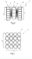
- a switching matrix (11, see. Fig. 3) known, in which the switching units (12) in several layers (16), namely an input layer, one Middle layer and an output layer are arranged.
- a such a switching matrix (11) is also referred to as a clos matrix.
- On the switching units (12) of the input layer are the Input channels (13) and on the switching units (12) Output layer arranged the output channels (14).
- the Switching units (12) of the different layers (16) linked together so that from each input channel (13) each output channel (14) has a path via the switching units (12) of the switching matrix (11) can be found.
- the well-known Switching matrix (11) has the disadvantage that it is only limited Broadcast and protection capabilities. From one Broadcast connection is called when of an input channel (13) a connection to several output channels (14) to be manufactured. the reverse case, a connection from several input channels (13) to one output channel (14) Establishing is called a protection connection. In addition, due to the large number of Links a very confusing structure. Thereby is the selection of a path from one Input channel (13) to any output channel (14) very much complex and difficult.
- switching matrix Switching matrices As another embodiment are a switching matrix Switching matrices (21, see. Fig. 4) known Switching units (22) in the form of a square matrix are arranged. Along a first side of the square Matrix (21), the input channels (23) are formed. The Output channels (24) are along a second side of the Matrix (21) formed.
- Such switching matrices (21) have full broadcast and protection capabilities. Besides, is with such switching matrices (21) the selection of a Paths from an input channel (23) to any one Output channel (24) much easier than in the above described Clos matrices (11).
- a quadratic switching matrix (21) has a very large number of switching units (22). Around full broadcast and protection capabilities enable, it has significantly more switching units (22) as, for example, the Clos matrices (11) from FIG. 3.
- the object of the present invention is a switching matrix of the type mentioned at the outset and to further develop that on the one hand a path from any Input channel to any output channel quickly and can be easily selected and that the switching matrix is full Broadcast and protection capabilities and that the Switching matrix on the other hand, the smallest possible number of switching units required.
- the invention proposes starting from the switching matrix of the type mentioned above that the Switching units arranged in a triangular matrix structure are.
- the triangular matrix structure is not one physical structure, but a purely logical structure. This means that the individual switching units are not are actually arranged in a triangular matrix structure, Rather, they can be arranged in obesity and only interconnected in a triangular matrix structure are.
- Simplification assumed that the switching matrix Structure of a lower triangular matrix, the columns of which left to right and their rows from bottom to top are numbered consecutively.
- the entrance channels are along one side of the triangle matrix and the output channels arranged along the other side of the triangular matrix.
- the switching matrix according to the invention can be easily and quickly a path from any input channel to one any output channel can be selected. Choosing one suitable path through the switching matrix bidirectional, d. H. the paths can also be from one any output channel to any input channel to be selected.
- the number is Switching units compared to the quadratic switching matrix reduced by almost half. More specifically, reduced the number of switching units compared to the quadratic switching matrix by the factor (n + 1) / 2n, where n is the Number of switching units along one side of the catheter Triangle matrix is. Due to the small number of required Switching units can reduce the manufacturing cost of one with the equipped switching matrix according to the invention Telecommunications system can be significantly reduced. So For example, in the case of a 40 x 40 switching matrix, the number of Switching units of 1,600 with the square switching matrix (see Fig. 4) to 820 ((40 + 1) / 80 * 1,600) at the switching matrix according to the invention can be reduced.
- the switching matrix according to the invention also has full Broadcast and protection capabilities. That is, it can be a Path for a connection from any input channel the switching matrix to any number of output channels or for the connection of any number of input channels the switching matrix selected for any output channel become. This is a decisive advantage over, for example the Clos matrix (see FIG. 3).
- the Switching units arranged in a triangular matrix structure.
- a triangular matrix structure is formed, through which the Input channels leading into the switching unit, and the output channels leading out of the switching unit, are interconnected. This way the number the links within the switching unit are reduced become.
- several Switching matrices also in a triangular matrix structure are arranged. This allows the number of switching matrices in a switching station in a telecommunications network be significantly reduced.
- the invention also relates to a selection method a path through a switching matrix in which the Switching units arranged in a triangular matrix structure are from one input channel of the switching matrix to one Output channel of the switching matrix.
- the invention proposes a selection process in which the shortest and the closest to the matrix diagonal Path is selected.
- connection line for one another path was selected, but this connecting line is already occupied by a previously selected path the path on the switching unit in front of this connecting line exceptionally down to the next switching unit branches. From there, an attempt is made again to next path to the matrix diagnostic to select.
- an input channel is to be connected to a plurality of output channels Q k (broadcast connection)
- a connecting line can be used for several connections from the input channel to the output channels at the same time, since the same data signal is passed from the input channel to the output channels.
- connection line can also be used for several connections from the input channels to the output channel at the same time, since the same data signal is routed from the input channels to the output channel.
- the Invention proposed that if for a connection of no path through an input channel with an output channel the switching matrix via selected connecting lines and selected switching units can be selected because already a path of a broadcast connection and / or one Protection connection has been selected by the switching matrix is to first select all paths where a Input channel is to be connected to an output channel, and only then the path of the broadcast connection and / or the Protection connection is selected.
- the paths in the Switch matrix can be selected again.
- the Advanced training that all paths are selected first, where an input channel is connected to an output channel and then the path of the broadcast connection and / or the protection connection is selected.
- Both Connections between an input channel and one As already explained above, the output channel must be on it be made sure that a connecting line is not for several Connections, d. H. for different paths, at the same time is used. So it is for such connections more difficult to choose a path through the switching matrix.
- a connecting line can be used for several connections within a broadcast or protection connection can be used because all paths of a broadcast connection or a protection connection the same Data signal is transmitted and therefore it does not become one Conflict on the paths of a broadcast connection or data signals transmitted to a protection connection can. So for such connections it is easier to get one Select path through the switching matrix.
- FIG. 1 shows a switching matrix for Applications in telecommunications in their entirety marked with the reference number 1.
- the switching matrix 1 points ten switching units 2 on, in a lower one Triangular matrix structure are arranged. On the left side the triangular matrix are input channels 3 and on the lower one Side of the triangular matrix output channels 4 are formed.
- the triangular matrix structure of the switching matrix 1 is concerned not a physical structure, but a pure one logical structure. That means the individual Switching units 2 are not actually in a triangular matrix structure are arranged, but rather arranged obese can be and only in a triangular matrix structure are interconnected.
- FIG. 2 shows the structure of a switching matrix 1 according to one shown second embodiment.
- the input channels 3 of the Switching matrix 1 are also over with the output channels 4 Switching units 2 connected in a triangular matrix structure are arranged.
- the Input channels 3 and the output channels 4 of the switching matrix 1 from Figure 2 are shown only symbolically. In reality stands each of the input channels 3 and each of the output channels 4 for multiple input channels 3 or for multiple output channels 4th
- n is the number of switching units 2 per catheter side of the triangular matrix.
- Each switching unit 2 is defined by the row s and the column t, ie by a point (t, s), within the structure of the switching matrix 1.
- a path is to be selected between an input channel P and a plurality of output channels Q k (broadcast connection)
- the method according to the invention is carried out for each of the output channels Q k .
- a path is to be selected between a plurality of input channels P k and an output channel Q (protection connection)
- the method is carried out for each of the input channels P k .
- k is a counter for a list of the output channels Q k or the input channels P k .
- the previously selected path 5 can be a path of a broadcast or a protection connection or else a path between an input channel 3 and an output channel 4.
Landscapes
- Engineering & Computer Science (AREA)
- Computer Networks & Wireless Communication (AREA)
- Use Of Switch Circuits For Exchanges And Methods Of Control Of Multiplex Exchanges (AREA)
Applications Claiming Priority (2)
| Application Number | Priority Date | Filing Date | Title |
|---|---|---|---|
| DE1998159832 DE19859832A1 (de) | 1998-12-23 | 1998-12-23 | Schaltmatrix für Telekommunikationsanwendungen |
| DE19859832 | 1998-12-23 |
Publications (1)
| Publication Number | Publication Date |
|---|---|
| EP1014754A2 true EP1014754A2 (fr) | 2000-06-28 |
Family
ID=7892513
Family Applications (1)
| Application Number | Title | Priority Date | Filing Date |
|---|---|---|---|
| EP19990440363 Withdrawn EP1014754A2 (fr) | 1998-12-23 | 1999-12-20 | Matrice de commutation pour applications de télécommunications |
Country Status (2)
| Country | Link |
|---|---|
| EP (1) | EP1014754A2 (fr) |
| DE (1) | DE19859832A1 (fr) |
Cited By (1)
| Publication number | Priority date | Publication date | Assignee | Title |
|---|---|---|---|---|
| EP1433254A4 (fr) * | 2001-09-19 | 2005-09-14 | Immersion Corp | Circuit et procede pour matrice de commutation et detection de commutateur |
-
1998
- 1998-12-23 DE DE1998159832 patent/DE19859832A1/de not_active Withdrawn
-
1999
- 1999-12-20 EP EP19990440363 patent/EP1014754A2/fr not_active Withdrawn
Cited By (3)
| Publication number | Priority date | Publication date | Assignee | Title |
|---|---|---|---|---|
| EP1433254A4 (fr) * | 2001-09-19 | 2005-09-14 | Immersion Corp | Circuit et procede pour matrice de commutation et detection de commutateur |
| US7151432B2 (en) | 2001-09-19 | 2006-12-19 | Immersion Corporation | Circuit and method for a switch matrix and switch sensing |
| EP2012431A1 (fr) | 2001-09-19 | 2009-01-07 | Immersion Corporation | Circuit et procédé pour une matrice de commutation et détection de commutation |
Also Published As
| Publication number | Publication date |
|---|---|
| DE19859832A1 (de) | 2000-06-29 |
Similar Documents
| Publication | Publication Date | Title |
|---|---|---|
| DE69226075T2 (de) | Kommunikationskoppelfeld | |
| EP0399139B1 (fr) | Méthode d'extension d'un champ de couplage régulier à trois étages | |
| DE69633053T2 (de) | Verfahren zur zuordnung von wellenlängenkanälen in einem optischen busnetz | |
| EP0058750A1 (fr) | Circuit pour centraux de télécommunications à division temporel, particulièrement centraux téléphoniques MIC ayant des canaux de données entre un organe de commande central et des dispositifs de commande décentralisés | |
| DE2713610A1 (de) | Pcm-zeitmultiplexkoppelfeld | |
| DE1107726B (de) | Verfahren und Schaltungsanordnung zum Suchen und Auswaehlen von freien Verbindungswegen in einem mehrstufigen Feld von Koppelpunkten | |
| DE2803065C2 (de) | Unbegrenzt erweiterbares Umkehrkoppelfeld für Fernmelde- insbesondere Fernsprechanlagen | |
| DE1487623C3 (de) | Koppeleinrichtung, insbesondere für eine Fernsprechvermittlungsanlage | |
| DE2262235C2 (de) | Mehrstufiges Koppelfeld zur Vermittlung von Zeitmultiplexnachrichten | |
| EP1014754A2 (fr) | Matrice de commutation pour applications de télécommunications | |
| DE1512947C3 (de) | Schaltungsanordnung für Fernmeldevermittlungsanlagen mit mehrstufigen Koppelfeldern, insbesondere für Fernsprechanlagen Siemens AG, 1000 Berlin und 8000 München | |
| DE3318544C1 (de) | Fernmeldenetz, insbesondere Fernsprechnetz, mit Netzknoten miteinander verbindenden und Netzausläufer bildenden Verbindungsleitungsbündeln | |
| DE2214202C2 (de) | Zeitfliultiplexkoppelanordnung | |
| DE2250516B2 (de) | Fernmeldenetzwerk mit sternfoermiger struktur | |
| DE3640849C2 (fr) | ||
| DE3634863C2 (de) | Schaltungsanordnung für eine zentralgesteuerte Fernmeldevermittlungsanlage, insbesondere PCM-Fernsprechvermittlungsanlage, mit einem Zentralteil und mit diesem verbundenen Anschlußgruppen | |
| DE2602129C3 (de) | Schaltungsanordnung fur Fernmelde· vermlttlungsanlagen, insbesondere Fernsprechvermittlungsanlagen mit mehrstufigen Koppelfeldern | |
| DE2659178C2 (de) | Koppelanordnung, insbesondere für den Anschluß von Zeitmultiplexleitungen | |
| DE2446391A1 (de) | Zeitmultiplexkoppelfeld | |
| DE2602561B2 (de) | Zeitmultiplexkoppelfeld | |
| DE4010146A1 (de) | Multiplexer fuer paketvermittlungsanlagen | |
| DE2553407C3 (de) | Schaltungsanordnung für Fernmeldevermittlungsanlagen, insbesondere Fernsprechvermittlungsanlagen, mit Koppelfeldern mit Umkehrgruppierung | |
| DE1512933C3 (de) | Verfahren zur Erweiterung teilausgebauter Koppelanordnungen der Fernmeldetechnik | |
| DE19905708C1 (de) | Verfahren zur Administration von zusammengehörenden PCM-Kanälen für Mehrkanalverbindungen | |
| DE3613051C2 (de) | Koppelnetzbaustein für optische Signale |
Legal Events
| Date | Code | Title | Description |
|---|---|---|---|
| PUAI | Public reference made under article 153(3) epc to a published international application that has entered the european phase |
Free format text: ORIGINAL CODE: 0009012 |
|
| AK | Designated contracting states |
Kind code of ref document: A2 Designated state(s): AT BE CH CY DE DK ES FI FR GB GR IE IT LI LU MC NL PT SE |
|
| AX | Request for extension of the european patent |
Free format text: AL;LT;LV;MK;RO;SI |
|
| STAA | Information on the status of an ep patent application or granted ep patent |
Free format text: STATUS: THE APPLICATION IS DEEMED TO BE WITHDRAWN |
|
| 18D | Application deemed to be withdrawn |
Effective date: 20030701 |