EP1014760A2 - Commande d'un faisceau de rayons-X pour un système d'imagérie - Google Patents
Commande d'un faisceau de rayons-X pour un système d'imagérie Download PDFInfo
- Publication number
- EP1014760A2 EP1014760A2 EP99310426A EP99310426A EP1014760A2 EP 1014760 A2 EP1014760 A2 EP 1014760A2 EP 99310426 A EP99310426 A EP 99310426A EP 99310426 A EP99310426 A EP 99310426A EP 1014760 A2 EP1014760 A2 EP 1014760A2
- Authority
- EP
- European Patent Office
- Prior art keywords
- voltage
- accordance
- ray tube
- ray
- switch element
- Prior art date
- Legal status (The legal status is an assumption and is not a legal conclusion. Google has not performed a legal analysis and makes no representation as to the accuracy of the status listed.)
- Granted
Links
Images


Classifications
-
- H—ELECTRICITY
- H05—ELECTRIC TECHNIQUES NOT OTHERWISE PROVIDED FOR
- H05G—X-RAY TECHNIQUE
- H05G1/00—X-ray apparatus involving X-ray tubes; Circuits therefor
- H05G1/08—Electrical details
- H05G1/26—Measuring, controlling or protecting
- H05G1/30—Controlling
- H05G1/32—Supply voltage of the X-ray apparatus or tube
Definitions
- a switching unit or circuit, which adjusts the signals applied to the x-ray source so that the magnitude and duration of the x-ray beams emitted from the x-ray tube are altered. It would also be desirable to provide a switching unit which includes any number of modular switching elements which may be combined to provide incremental control of the tube signals as required by the application while minimizing cost of the switching unit. Additionally, it would also be desirable to provide such a unit which utilizes a beam or beams of light to control the switching elements to provide isolation from the high voltage tube signals.
- the switching unit includes any number of switch elements for altering a grid bias voltage supplied to the x-ray tube, an insulating support structure for securing the modular switch elements together, and an electrostatic shield for eliminating corona discharge from the switch elements.
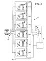
- Each switch element utilizes a beam of light excitation signal to alternate between two different modes, or states, of operation. These states of operation are sometimes referred to herein as the conduction state and the steady state.
- the conduction state if an excitation signal is received by the switch element, a switch element voltage drop across the element becomes approximately zero and a maximum signal is applied to the x-ray tube so that a maximum number of x-rays are emitted from the x-ray source.
- the steady state refers to the condition when an excitation signal is not received by a switch element. In the steady state, a voltage drop is generated by the switch element so that the signal applied to the x-ray tube is decreased by an amount determined by a voltage drop element.
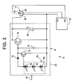
- the voltage signal supplied to control grid 28 from unit 32 is the voltage signal supplied from power supply 30 to unit 32 less the voltage drop across element 80, i.e, 1,000 volts.
- the output of power supply 30 is - 20,000 volts
- approximately -19,000 volts is supplied to control grid 28 and a voltage drop of approximately 1,000 volts exists across drop element 80.
- the voltage drop across element 80 is approximately zero and the current flows through FET 78 so that approximately -20,000 volts is supplied to control grid 28.
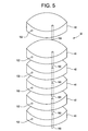
- switching unit 32 utilizes a plurality of switch elements 40 and excitation signals 34 so that the total voltage drop across switch unit 32 is altered to change the duration and magnitude of the x-ray beams emitted from tube 14.
- each switch element may be placed in the steady state or conduction mode so that the total voltage drop varies the according to the combined value of drop elements 80.
- elements 40 are configured to interconnect with each other so that additional elements may be quickly and easily added or removed to achieve the desired total voltage drop and voltage drop increment size of unit 32.
- modular switch elements 40 are coupled together utilizing intermodule connectors 100.
- the voltage and current signals are transmitted from unit 32 to tube 14 utilizing an external high voltage cable (not shown in Figure 5) coupled to switch elements 40.
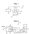
- excitations signals 34 are timed so that the x-ray beams are emitted from tube 14 only when image data, or information, is being collected by system 10. After the data has been collected, excitation signals 34 are transitioned so that the excitation signals 34 are not transmitted to unit 32. Consequently, the x-ray beams are not emitted from tube 14. Utilizing unit 32, the x-ray beams are emitted only when needed and turned off when the x-ray beams are not being used to generate image data. As a result, the x-ray dosage received by patient 24 is reduced. Additionally, the magnitude of the x-ray beams emitted from tube 14 may be altered by selectively transmitting individual excitation signals 34 to unit 32 as described above.
- unit 200 alters the duration and magnitude of the x-ray beams by altering the voltage and current signals applied to cathode 66 of tube 14.
- Unit 200 is identical to unit 32 as described above, except the duration and magnitude of x-ray beams emitted from tube 14 are altered by modifying the voltage and current applied to cathode 26. Specifically, by applying different excitation signals 34 to unit 200, the voltage drop across unit 200 is altered so that the voltage and current signal applied to cathode 26 is altered.
Landscapes
- Health & Medical Sciences (AREA)
- General Health & Medical Sciences (AREA)
- Toxicology (AREA)
- X-Ray Techniques (AREA)
- Apparatus For Radiation Diagnosis (AREA)
Applications Claiming Priority (2)
| Application Number | Priority Date | Filing Date | Title |
|---|---|---|---|
| US218347 | 1994-03-28 | ||
| US09/218,347 US6215850B1 (en) | 1998-12-22 | 1998-12-22 | X-ray beam control for an imaging system |
Publications (3)
| Publication Number | Publication Date |
|---|---|
| EP1014760A2 true EP1014760A2 (fr) | 2000-06-28 |
| EP1014760A3 EP1014760A3 (fr) | 2001-09-05 |
| EP1014760B1 EP1014760B1 (fr) | 2009-03-18 |
Family
ID=22814745
Family Applications (1)
| Application Number | Title | Priority Date | Filing Date |
|---|---|---|---|
| EP99310426A Expired - Lifetime EP1014760B1 (fr) | 1998-12-22 | 1999-12-22 | Commande d'un faisceau de rayons-X pour un système d'imagérie |
Country Status (5)
| Country | Link |
|---|---|
| US (1) | US6215850B1 (fr) |
| EP (1) | EP1014760B1 (fr) |
| JP (1) | JP4460696B2 (fr) |
| DE (1) | DE69940589D1 (fr) |
| IL (1) | IL133324A (fr) |
Families Citing this family (17)
| Publication number | Priority date | Publication date | Assignee | Title |
|---|---|---|---|---|
| JP4497640B2 (ja) * | 2000-03-29 | 2010-07-07 | 株式会社日立メディコ | 高電圧スイッチ回路及びこれを用いたx線装置 |
| CN1846621A (zh) * | 2005-04-15 | 2006-10-18 | 株式会社东芝 | Ct扫描机 |
| DE102005020898B4 (de) * | 2005-05-04 | 2016-02-18 | Siemens Aktiengesellschaft | Verfahren und Röntgeneinrichtung zur Durchleuchtung eines in variablem Abstand zu einer Röntgenquelle platzierbaren Patienten |
| JP5335185B2 (ja) * | 2006-10-16 | 2013-11-06 | 株式会社日立メディコ | 高電圧発生装置 |
| US7844030B2 (en) * | 2008-03-26 | 2010-11-30 | General Electric Company | System and method of fast switching for spectral imaging |
| CN102119000B (zh) * | 2008-08-08 | 2013-08-07 | 皇家飞利浦电子股份有限公司 | 电压调制的x射线管 |
| US7742573B2 (en) * | 2008-10-17 | 2010-06-22 | General Electric Company | Fast switching circuit for x-ray imaging applications |
| US8027433B2 (en) * | 2009-07-29 | 2011-09-27 | General Electric Company | Method of fast current modulation in an X-ray tube and apparatus for implementing same |
| US8396185B2 (en) | 2010-05-12 | 2013-03-12 | General Electric Company | Method of fast current modulation in an X-ray tube and apparatus for implementing same |
| US20120236996A1 (en) | 2011-03-16 | 2012-09-20 | Intellirad Control, Inc. | Radiation control and minimization system and method |
| WO2013105011A2 (fr) * | 2012-01-11 | 2013-07-18 | Controlrad Systems, Inc. | Tube à rayons x |
| JP6169890B2 (ja) * | 2013-05-20 | 2017-07-26 | 東芝メディカルシステムズ株式会社 | X線管制御装置及びx線ct装置 |
| JP6188470B2 (ja) * | 2013-07-24 | 2017-08-30 | キヤノン株式会社 | 放射線発生装置及びそれを用いた放射線撮影システム |
| JP6441015B2 (ja) * | 2014-10-06 | 2018-12-19 | キヤノンメディカルシステムズ株式会社 | X線診断装置及びx線管制御方法 |
| DE102016222365B3 (de) * | 2016-11-15 | 2018-04-05 | Siemens Healthcare Gmbh | Verfahren, Computerprogrammprodukt, computerlesbares Medium und Vorrichtung zur Erzeugung von Röntgenpulsen bei einer Röntgenbildgebung |
| US12557202B2 (en) * | 2023-10-10 | 2026-02-17 | GE Precision Healthcare LLC | Strategy for controlling cathode width voltage |
| CN120233818A (zh) * | 2023-12-28 | 2025-07-01 | 武汉联影医疗科技有限公司 | 多电压输出电路、栅极结构电压控制电路、x射线设备 |
Family Cites Families (7)
| Publication number | Priority date | Publication date | Assignee | Title |
|---|---|---|---|---|
| CH389039A (de) * | 1961-07-20 | 1965-03-15 | Standard Telephon & Radio Ag | Spannungsstabilisierte Gleichstromspeiseeinrichtung |
| US3567995A (en) * | 1968-08-12 | 1971-03-02 | Automation Ind Inc | Current stabilizer circuit for thermionic electron emission device |
| US4013936A (en) * | 1975-11-12 | 1977-03-22 | General Electric Company | Regulated high voltage d.c. supply utilizing a plurality of d.c. to d.c. converter modules |
| DE3401367A1 (de) * | 1984-01-17 | 1985-07-25 | Elektrowerk Mündersbach GmbH, 5419 Mündersbach | Verfahren zum herstellen einer in einem gehaeuse gasdicht gekapselten funkenstrecke |
| EP0236573A3 (fr) * | 1986-01-03 | 1988-08-10 | General Electric Company | Tube à rayons X résistant à la soudure |
| US5077771A (en) * | 1989-03-01 | 1991-12-31 | Kevex X-Ray Inc. | Hand held high power pulsed precision x-ray source |
| US5241260A (en) * | 1989-12-07 | 1993-08-31 | Electromed International | High voltage power supply and regulator circuit for an X-ray tube with transient voltage protection |
-
1998
- 1998-12-22 US US09/218,347 patent/US6215850B1/en not_active Expired - Lifetime
-
1999
- 1999-11-30 JP JP33898799A patent/JP4460696B2/ja not_active Expired - Lifetime
- 1999-12-06 IL IL13332499A patent/IL133324A/xx not_active IP Right Cessation
- 1999-12-22 DE DE69940589T patent/DE69940589D1/de not_active Expired - Lifetime
- 1999-12-22 EP EP99310426A patent/EP1014760B1/fr not_active Expired - Lifetime
Also Published As
| Publication number | Publication date |
|---|---|
| EP1014760A3 (fr) | 2001-09-05 |
| IL133324A (en) | 2003-11-23 |
| IL133324A0 (en) | 2001-04-30 |
| JP2000195697A (ja) | 2000-07-14 |
| US6215850B1 (en) | 2001-04-10 |
| JP4460696B2 (ja) | 2010-05-12 |
| DE69940589D1 (de) | 2009-04-30 |
| EP1014760B1 (fr) | 2009-03-18 |
Similar Documents
| Publication | Publication Date | Title |
|---|---|---|
| US6215850B1 (en) | X-ray beam control for an imaging system | |
| US4277679A (en) | Apparatus and method for contact-free potential measurements of an electronic composition | |
| US5617464A (en) | Cathode system for an x-ray tube | |
| US3937965A (en) | Radiography apparatus | |
| US3833811A (en) | Scanning electron microscope with improved means for focusing | |
| Donaldson et al. | A self-calibrating, multichannel streak camera for inertial confinement fusion applications | |
| CN1443435A (zh) | X-射线源 | |
| JP2000195697A5 (fr) | ||
| US4097740A (en) | Method and apparatus for focusing the objective lens of a scanning transmission-type corpuscular-beam microscope | |
| US3955116A (en) | Circuit arrangement suitable for use in a television pick-up tube provided with an anti-comet tail electron gun | |
| RU97100939A (ru) | Видеосистема с источником питания экранирующей сетки, реагирующей на арнс- систему | |
| US20030021380A1 (en) | X-ray system for forming X-ray images | |
| EP4291882A1 (fr) | Système et procédé de commande de champ de tube de glissement | |
| US6094473A (en) | Digital automatic X-ray exposure control system | |
| IT8349351A1 (it) | Tubo per raggi X a punto focale regolabile. | |
| US6399934B1 (en) | Optical coupling to gated photocathodes | |
| EP1066648A1 (fr) | Reglage du temps de propagation et du gain de tubes photomultiplicateurs | |
| US6486461B1 (en) | Method and system for regulating a high voltage level in a power supply for a radiation detector | |
| CN111446141A (zh) | 一种多路高精度高压电源 | |
| US5656808A (en) | Method for the use of an X-ray image intensifier tube and circuit for the implementation of the method | |
| KR102781945B1 (ko) | 엑스선 소스의 구동장치 및 이를 이용한 엑스선 발생장치 | |
| Ross | Beam diagnostics and control for SLC | |
| CA1149076A (fr) | Generatrice haute tension a potentiel constant | |
| Miller et al. | Beam profile measurements in the RHIC electron lens using a pinhole detector and YAG screen | |
| JPH0383000A (ja) | X線顕微鏡 |
Legal Events
| Date | Code | Title | Description |
|---|---|---|---|
| PUAI | Public reference made under article 153(3) epc to a published international application that has entered the european phase |
Free format text: ORIGINAL CODE: 0009012 |
|
| AK | Designated contracting states |
Kind code of ref document: A2 Designated state(s): AT BE CH CY DE DK ES FI FR GB GR IE IT LI LU MC NL PT SE |
|
| AX | Request for extension of the european patent |
Free format text: AL;LT;LV;MK;RO;SI |
|
| PUAL | Search report despatched |
Free format text: ORIGINAL CODE: 0009013 |
|
| AK | Designated contracting states |
Kind code of ref document: A3 Designated state(s): AT BE CH CY DE DK ES FI FR GB GR IE IT LI LU MC NL PT SE |
|
| AX | Request for extension of the european patent |
Free format text: AL;LT;LV;MK;RO;SI |
|
| 17P | Request for examination filed |
Effective date: 20020305 |
|
| AKX | Designation fees paid |
Free format text: DE NL |
|
| 17Q | First examination report despatched |
Effective date: 20060220 |
|
| GRAP | Despatch of communication of intention to grant a patent |
Free format text: ORIGINAL CODE: EPIDOSNIGR1 |
|
| GRAS | Grant fee paid |
Free format text: ORIGINAL CODE: EPIDOSNIGR3 |
|
| GRAA | (expected) grant |
Free format text: ORIGINAL CODE: 0009210 |
|
| AK | Designated contracting states |
Kind code of ref document: B1 Designated state(s): DE NL |
|
| REF | Corresponds to: |
Ref document number: 69940589 Country of ref document: DE Date of ref document: 20090430 Kind code of ref document: P |
|
| PLBE | No opposition filed within time limit |
Free format text: ORIGINAL CODE: 0009261 |
|
| STAA | Information on the status of an ep patent application or granted ep patent |
Free format text: STATUS: NO OPPOSITION FILED WITHIN TIME LIMIT |
|
| 26N | No opposition filed |
Effective date: 20091221 |
|
| PGFP | Annual fee paid to national office [announced via postgrant information from national office to epo] |
Ref country code: DE Payment date: 20111229 Year of fee payment: 13 |
|
| PGFP | Annual fee paid to national office [announced via postgrant information from national office to epo] |
Ref country code: NL Payment date: 20120103 Year of fee payment: 13 |
|
| REG | Reference to a national code |
Ref country code: NL Ref legal event code: V1 Effective date: 20130701 |
|
| PG25 | Lapsed in a contracting state [announced via postgrant information from national office to epo] |
Ref country code: DE Free format text: LAPSE BECAUSE OF NON-PAYMENT OF DUE FEES Effective date: 20130702 Ref country code: NL Free format text: LAPSE BECAUSE OF NON-PAYMENT OF DUE FEES Effective date: 20130701 |
|
| REG | Reference to a national code |
Ref country code: DE Ref legal event code: R119 Ref document number: 69940589 Country of ref document: DE Effective date: 20130702 |