EP1014878B1 - Plaque spinale modulaire - Google Patents
Plaque spinale modulaire Download PDFInfo
- Publication number
- EP1014878B1 EP1014878B1 EP98920918A EP98920918A EP1014878B1 EP 1014878 B1 EP1014878 B1 EP 1014878B1 EP 98920918 A EP98920918 A EP 98920918A EP 98920918 A EP98920918 A EP 98920918A EP 1014878 B1 EP1014878 B1 EP 1014878B1
- Authority
- EP
- European Patent Office
- Prior art keywords
- shaft
- cuff
- stem
- coupling element
- assembly
- Prior art date
- Legal status (The legal status is an assumption and is not a legal conclusion. Google has not performed a legal analysis and makes no representation as to the accuracy of the status listed.)
- Expired - Lifetime
Links
- 230000008878 coupling Effects 0.000 claims abstract description 73
- 238000010168 coupling process Methods 0.000 claims abstract description 73
- 238000005859 coupling reaction Methods 0.000 claims abstract description 73
- 210000000988 bone and bone Anatomy 0.000 claims abstract description 14
- 230000006835 compression Effects 0.000 claims abstract description 10
- 238000007906 compression Methods 0.000 claims abstract description 10
- 238000007747 plating Methods 0.000 claims description 16
- 239000007943 implant Substances 0.000 abstract description 2
- 238000005056 compaction Methods 0.000 abstract 2
- 230000004323 axial length Effects 0.000 description 6
- 238000000034 method Methods 0.000 description 5
- 238000002513 implantation Methods 0.000 description 2
- 230000007774 longterm Effects 0.000 description 2
- 210000000653 nervous system Anatomy 0.000 description 2
- HGQPLNKSYJFALV-UHFFFAOYSA-N C(C1CC2)C1C1C2CCCCCC1 Chemical compound C(C1CC2)C1C1C2CCCCCC1 HGQPLNKSYJFALV-UHFFFAOYSA-N 0.000 description 1
- 206010028980 Neoplasm Diseases 0.000 description 1
- 210000003484 anatomy Anatomy 0.000 description 1
- 230000000712 assembly Effects 0.000 description 1
- 238000000429 assembly Methods 0.000 description 1
- 230000008901 benefit Effects 0.000 description 1
- 210000000845 cartilage Anatomy 0.000 description 1
- 230000037326 chronic stress Effects 0.000 description 1
- 210000002808 connective tissue Anatomy 0.000 description 1
- 201000010099 disease Diseases 0.000 description 1
- 208000037265 diseases, disorders, signs and symptoms Diseases 0.000 description 1
- 230000004927 fusion Effects 0.000 description 1
- 230000002068 genetic effect Effects 0.000 description 1
- 208000014674 injury Diseases 0.000 description 1
- 238000003780 insertion Methods 0.000 description 1
- 230000037431 insertion Effects 0.000 description 1
- 230000007246 mechanism Effects 0.000 description 1
- 238000012986 modification Methods 0.000 description 1
- 230000004048 modification Effects 0.000 description 1
- 230000000399 orthopedic effect Effects 0.000 description 1
- 230000007170 pathology Effects 0.000 description 1
- 210000000578 peripheral nerve Anatomy 0.000 description 1
- 230000009467 reduction Effects 0.000 description 1
- 125000006850 spacer group Chemical group 0.000 description 1
- 230000007480 spreading Effects 0.000 description 1
- 230000008733 trauma Effects 0.000 description 1
- 210000002517 zygapophyseal joint Anatomy 0.000 description 1
Images


Classifications
-
- A—HUMAN NECESSITIES
- A61—MEDICAL OR VETERINARY SCIENCE; HYGIENE
- A61B—DIAGNOSIS; SURGERY; IDENTIFICATION
- A61B17/00—Surgical instruments, devices or methods
- A61B17/56—Surgical instruments or methods for treatment of bones or joints; Devices specially adapted therefor
- A61B17/58—Surgical instruments or methods for treatment of bones or joints; Devices specially adapted therefor for osteosynthesis, e.g. bone plates, screws or setting implements
- A61B17/68—Internal fixation devices, including fasteners and spinal fixators, even if a part thereof projects from the skin
- A61B17/70—Spinal positioners or stabilisers, e.g. stabilisers comprising fluid filler in an implant
- A61B17/7001—Screws or hooks combined with longitudinal elements which do not contact vertebrae
- A61B17/7041—Screws or hooks combined with longitudinal elements which do not contact vertebrae with single longitudinal rod offset laterally from single row of screws or hooks
-
- A—HUMAN NECESSITIES
- A61—MEDICAL OR VETERINARY SCIENCE; HYGIENE
- A61B—DIAGNOSIS; SURGERY; IDENTIFICATION
- A61B17/00—Surgical instruments, devices or methods
- A61B17/56—Surgical instruments or methods for treatment of bones or joints; Devices specially adapted therefor
- A61B17/58—Surgical instruments or methods for treatment of bones or joints; Devices specially adapted therefor for osteosynthesis, e.g. bone plates, screws or setting implements
- A61B17/68—Internal fixation devices, including fasteners and spinal fixators, even if a part thereof projects from the skin
- A61B17/70—Spinal positioners or stabilisers, e.g. stabilisers comprising fluid filler in an implant
- A61B17/7001—Screws or hooks combined with longitudinal elements which do not contact vertebrae
- A61B17/7002—Longitudinal elements, e.g. rods
- A61B17/7004—Longitudinal elements, e.g. rods with a cross-section which varies along its length
- A61B17/7007—Parts of the longitudinal elements, e.g. their ends, being specially adapted to fit around the screw or hook heads
-
- A—HUMAN NECESSITIES
- A61—MEDICAL OR VETERINARY SCIENCE; HYGIENE
- A61B—DIAGNOSIS; SURGERY; IDENTIFICATION
- A61B17/00—Surgical instruments, devices or methods
- A61B17/56—Surgical instruments or methods for treatment of bones or joints; Devices specially adapted therefor
- A61B17/58—Surgical instruments or methods for treatment of bones or joints; Devices specially adapted therefor for osteosynthesis, e.g. bone plates, screws or setting implements
- A61B17/68—Internal fixation devices, including fasteners and spinal fixators, even if a part thereof projects from the skin
- A61B17/70—Spinal positioners or stabilisers, e.g. stabilisers comprising fluid filler in an implant
- A61B17/7001—Screws or hooks combined with longitudinal elements which do not contact vertebrae
- A61B17/7002—Longitudinal elements, e.g. rods
- A61B17/701—Longitudinal elements with a non-circular, e.g. rectangular, cross-section
-
- A—HUMAN NECESSITIES
- A61—MEDICAL OR VETERINARY SCIENCE; HYGIENE
- A61B—DIAGNOSIS; SURGERY; IDENTIFICATION
- A61B17/00—Surgical instruments, devices or methods
- A61B17/56—Surgical instruments or methods for treatment of bones or joints; Devices specially adapted therefor
- A61B17/58—Surgical instruments or methods for treatment of bones or joints; Devices specially adapted therefor for osteosynthesis, e.g. bone plates, screws or setting implements
- A61B17/68—Internal fixation devices, including fasteners and spinal fixators, even if a part thereof projects from the skin
- A61B17/70—Spinal positioners or stabilisers, e.g. stabilisers comprising fluid filler in an implant
- A61B17/7001—Screws or hooks combined with longitudinal elements which do not contact vertebrae
- A61B17/7035—Screws or hooks, wherein a rod-clamping part and a bone-anchoring part can pivot relative to each other
- A61B17/7037—Screws or hooks, wherein a rod-clamping part and a bone-anchoring part can pivot relative to each other wherein pivoting is blocked when the rod is clamped
Definitions
- This invention relates generally to a spinal plating system for use with modular polyaxial pedicle screws. More particularly, the present invention relates to a modular plating assembly which receives modular polyaxial screws, and which may thereby be attached to the posterior or anterior-lateral surfaces of the vertebral column to immobilize the same.
- the bones and connective tissue of an adult human spinal column consists of more than 20 discrete bones coupled sequentially to one another by a tri-joint complex which consist of an anterior disc and the two posterior facet joints, the anterior discs of adjacent bones being cushioned by cartilage spacers referred to as intervertebral discs.
- This structure houses and protects critical elements of the nervous system while also having innumerable peripheral nerves and circulatory bodies in close proximity.
- the spine is a highly flexible structure, capable of a high degree of curvature and twist in nearly every direction.
- These implant systems generally comprise multiple screws which are inserted into sequential vertebral bones, which screws are then rigidly coupled together with a rod or plate. It has been identified, however, that patient anatomy often necessitates the insertion of the screws at non-parallel relative alignments. If the heads of the screws are not flexible, it is correspondingly difficult to contour the rods or plates to seat on, or in the heads of the screws.
- US-A-5620443 The preamble of claim 1 is based on this document discloses a transverse fixator assembly for spanning between a number of longitudinal members situated adjacent a patient's vertebrae and methods for fixation of the spine which allow variation of the distance between two or more vertebrae.
- the assembly includes a number of connectors configured to span the distance between and engage the longitudinal members.
- the connectors define a thru-hole for engaging a bone bolt which is engaged to a vertebra plus a number of spikes projecting from the connector.
- a locking mechanism is configured to prevent the bolt from rotating relative to the connector when the nut is being tightened.
- One or more of the connectors may be a dynamic connector which is slidably engaged to the longitudinal members to vary the distance between the vertebrae for compression or distraction.
- US-A-5613968 discloses an orthopedic fixation device including a fixation ring, a universal pad, a threaded fixation element, and a fastening nut.
- the universal pad contains a circular hole and is provided at one end with a protruding arcuate surface and at another end with a recessed arcuate surface concentric with the protruding arcuate surface.
- the fastening nut is provided with a protruding or recessed arcuate surface located at one side facing the universal pad.
- the threaded fixation element has an arresting portion which is provided with a protruding or recessed arcuate surface located at one side facing the universal pad. The protruding and recessed arcuate surfaces of the fastening nut and the threaded fixation element are engageable with the universal pad.
- a modular spinal plating assembly for use with spinal screws having post portions which are extendable above the vertebral bone, comprising:
- the spinal plating system comprises an elongate track, consisting of a pair of rails, spaced apart in parallel, coupled at each end.
- the rails slidably receive, thereabout, a multiplicity of compressible coupling elements.
- Each compressible coupling element comprises a first through hole into which the parallel rails are inserted in a manner which permits the coupling element to slide along the axial length of the track prior to it being compressed.
- a second through hole in the coupling element is provided so that it may receive the threaded shaft of a pedicle screw assembly such as are shown in U.S. Patents 5,735,851 and 5,725,528 mentioned above.
- the coupling elements each comprise a pair of slots on the outer lateral edges (the edges adjacent to, and laterally containing, the rails of the track element when same is inserted into the coupling element).
- the slots extend for more than half the axial length of the coupling element, and are directed in opposite directions. These slots permit the coupling element to deflect compressibly upon the application of a compressive force. This deflection causes the coupling element to rigidly lock to the rails.
- the modular polyaxial screw comprises: a threaded shaft portion, which is inserted into the vertebral bone, the top of shaft portion including a bowl-shaped socket and a second threading; a stem portion having a threading for receiving a locking nut, the bottom of the stem portion being ball-shaped (a semi-spherical section); and a cylindrical locking cuff which is mounted about the ball-shaped bottom of the stem and threadably secured to the top of the shaft to secure the ball of the stem in the bowl-shaped socket of the shaft.
- the stem Prior to complete tightening of the cuff, the stem is polyaxially coupled to the shaft. Tightening of the cuff causes the ball-shaped end of the stem to be compression locked in the bowl-shaped socket of the shaft.
- the invention also provides a modular polyaxial pedicle screw and plating assembly, comprising:
- the invention further provides a modular polyaxial pedicle screw and planting assembly, comprising:
- a plurality of such polyaxial screws are implanted into the vertebral bone, and the stems are roughly positioned to receive the plating system and the cuffs are tightened thereby locking the stems in place.
- the appropriate number of compressible coupling elements are then slidably advanced onto the track element (the track element itself may be sized according to the requirements of the surgeon).
- the coupling elements are aligned in accordance with the positions of the stems, and each of the stems is then inserted through the second through hole of the corresponding compressible coupling element. It shall be understood that the rials and the openings in the coupling elements which comprise the second through holes are sufficiently contoured to receive stem portions which are not parallel to one another, and not perpendicular to the coupling element itself.
- a top locking nut is then advanced along the threading of the stem until it contacts the top surface of the compressible coupling element. Continued downward force applied by the nut causes the slots of the coupling element to narrow, and the coupling element to deflect. This deflection causes the coupling element to lock to the rails of the track element, thus completely securing the assembly together.
- FIG. 1a a modular polyaxial pedicle screw which may be used in conjunction with the present invention is provided.
- the shaft portion of this polyaxial screw is provided in Figure 1a, and includes a threaded bone screw portion 102, a hexagonal midportion 104 (which is provided so that the shaft portion may be driven into the bone by convention hexagonal screw driving means), and an upper socket portion 106.
- the upper socket portion 106 includes a bowl-shaped upper end 108 and a threaded cylindrical exterior surface 110.
- the stem portion 112 of this preferred modular polyaxial pedicle screw comprises an upper post portion 114, which is threaded, and a lower ball-shaped end 116 which has substantially the same radius of curvature as the bowl-shaped socket 108 of the shaft portion 102.
- This correspondence of shape permits the stem 112 to polyaxially rotate relative to the shaft 102 when the ball-shaped end 116 is seated loosely in the bowl-shaped socket 108.
- the cuff portion 122 of the preferred embodiment comprises a cylindrical element having a lower portion 124 which comprises an interior threading 126 which mates with the threaded upper exterior cylindrical surface 110 of the shaft portion.
- the cuff 122 further includes an upper interior socket 128 in which the upper portion of the ball-shaped end 116 of the stem may 112 be held.
- the upper portion 132 of the cuff 122 includes an opening 130 through which the post portion 114 of the stem may extend (and polyaxially angulate relative to the cuff and shaft).
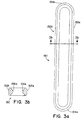
- the track element 150 itself simply comprises a pair of rails 152a,152b which extend in a spaced apart relationship, parallel to one another for an axial length of the track.
- the ends 154a,154b of the track 150 comprise inwardly curved and continguous ends of the rails 152a,152b such that the track maintains an elongated loop shape.
- the cross-section of the rails 152a,152b illustrated herein shows the curvate of the inwardly facing surfaces 156a,156b of the rails. This inward curvature is preferred insofar as it permits greater flexibility of coupling with a post portion 114 of a pedicle screw as it allows a range of entrance angles of the post 114 between the rails (described more fully hereinbelow).
- the element 200 comprises a hollow rectangular body, having a first through hole 202 which extends therethrough.
- This first through hole 202 is designed to receive the axial length of the track element 150.
- the lateral inner surfaces 204a,204b are contoured to cup around the outer surfaces of the rails 152a, 152b, respectively, such that the coupling element 200 may slide freely along the axial length of the track 150.
- the coupling element includes a pair of slots 206a,206b formed in the lateral walls 204a,204b, respectively. The slots 206a,206b do extend for more than half, but less than fully through the axial length of the coupling element 200, and are diagonally opposing in their orientation (see Figure 4a).
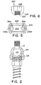
- FIG. 4a in which a top view of the compressible coupling element 200 is provided, the opposite sense of the incomplete slots 206a,206b is illustrated.
- a second through hole 208 extending through the upper and lower surfaces of the coupling element, is provided to receive the post 114 portion of a pedicle screw of the type illustrated and described with respect to Figures 1a-c and 2.
- the lips 210a,210b of the second through hole are tapered inwardly toward the hole in a manner which, like the taper of the inner surfaces 156a,156b of the rails, to permit easier coupling to non-perpendicularly received post portions 114.
- the embodiment shown in Figure 4c is an alternative side view of the coupling element which illustrates the incomplete nature of the slots (slot 206b being shown).
- the coupling element 200 is designed to be compressibly compactible insofar as the application of a downward force on the coupling element 200 causes the slots 206a,206b to deflect, therein narrowing. This narrowing, if forced when the coupling element 200 is mounted to the rail, as illustrated in Figure 5, causes the element to be compression locked to the rails 152a,152b. Therefore, the application of a sufficient compression force onto the compressible coupling element 200 when it is mounted to the track element 150 permits the two to be fully locked together (eliminating the slideability of the coupling element 200 relative to the axial extent of the track 150).
- top locking nut 220 which is provided to be threadably engaged onto the threading of the upper post portion of the the stem 114 of the pedicle screw is shown in a side cross-section view.
- the inner portion of the nut has a threading 222, while the exterior surface 224 is curvately tapered to be received into the tapered second through hole 208 of the compressible coupling element 200 independent of the non-perpendicular entrance of the post portion 114 thereinto.
- the top of the locking nut 220 may also include a hexagonal recess 226, or other such screw driving tool receiving orifice, so that it may be advanced onto the threaded post portion 114.
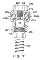
- the compressible coupling element 200 is then advanced into position along the rails 152a,152b of the track element 150.
- the threaded post portion 114 of the stem of the pedicle screw is then advanced through the second through hole 208 of the coupling element, until the upper portion of the cuff 122 seats into the tapered lower lip 210b of the coupling element 200.
- the top locking nut 220 is then threadably advanced onto the threaded post section 114 until the curvate bottom 224 of the nut seats in the upper opening of the second through hole 208, and against the upper lip 210a.
- Continued advancement of the top locking nut 220 causes a compressive force to be applied to the compressible coupling element 200.
- the applied load which build between the fixed cuff 122 and the top locking nut 220, causes the incomplete slots 206a,206b to narrow, thereby causing the coupling element to be compression locked to the rails 152a,152b.
- the advantage of having the coupling element 200 seat around the rails 152a,152b is to prevent the rails from expanding outwardly under the resultant (or any unforeseen) spreading force, such as the force of the top locking nut itself.
Landscapes
- Health & Medical Sciences (AREA)
- Orthopedic Medicine & Surgery (AREA)
- Life Sciences & Earth Sciences (AREA)
- Neurology (AREA)
- Surgery (AREA)
- Heart & Thoracic Surgery (AREA)
- General Health & Medical Sciences (AREA)
- Biomedical Technology (AREA)
- Nuclear Medicine, Radiotherapy & Molecular Imaging (AREA)
- Medical Informatics (AREA)
- Molecular Biology (AREA)
- Animal Behavior & Ethology (AREA)
- Engineering & Computer Science (AREA)
- Public Health (AREA)
- Veterinary Medicine (AREA)
- Surgical Instruments (AREA)
- Iron Core Of Rotating Electric Machines (AREA)
- Finger-Pressure Massage (AREA)
- Electromagnets (AREA)
Claims (5)
- Ensemble de pose de plaque rachidienne modulaire destiné à être utilisé avec des vis vertébrales ayant des parties broches qui sont extensibles au-dessus de l'os vertébral, comprenant :un élément chemin de guidage (150) comprenant une paire de rails parallèles écartés (152a, 152b) ; ledit ensemble comprenant également :au moins un élément d'accouplement compressible (200) comprenant
un premier trou traversant (202) pour recevoir à travers lui lesdits rails parallèles écartés (152a, 152b), et
un deuxième trou traversant (208) pour recevoir à travers lui une partie correspondante desdites parties broches (114) desdites vis vertébrales, et ;des moyens (220) pour accoupler lesdites parties broches (114) audit élément d'accouplement compressible correspondant (200),ledit élément étant caractérisé en ce que ledit élément d'accouplement compressible (200) comprend également
au moins une fente (206a, 206b), ladite fente pouvant être réduite en largeur par l'application d'une force de compression ; etdans lequel, en cours d'utilisation, lesdits moyens pour l'accouplement (220) fournissent également une force vers le bas sur ledit élément d'accouplement compressible (200), causant la réduction de la largeur de la au moins une fente (206a, 206b) et la compression correspondante de l'élément d'accouplement (200) de façon à ce que l'élément d'accouplement (220) soit bloqué par écrasement sur les rails (152a, 152b), et à ce que la vis pédiculaire correspondante (102) et l'ensemble plaque soient bloqués ensemble de manière rigide. - Ensemble tel que revendiqué dans la revendication 1, la au moins une fente (206a, 206b) du au moins un élément d'accouplement compressible (200) comportant une paire de fentes incomplètes décalées diagonalement sur les parties latérales opposées de celui-ci.
- Ensemble de pose de plaque et vis pédiculaires polyaxiales modulaires, comprenant :au moins deux vis pédiculaires (102, 106 ; 112, 122) ayant des parties broches supérieures (114), dont au moins une comprendun axe ayant une partie inférieure (102) et une partie supérieure (106), ladite partie supérieure (106) ayant un filetage (110) sur celle-ci et une cavité incurvée (108) formée dans un sommet de celle-ci,une tige (112) ayant une desdites parties broches supérieures (114) et une partie sphérique inférieure (116), cette partie sphérique (116) étant formée de façon à s'emboîter et à tourner initialement dans ladite cavité incurvée (108), etun manchon (122) ayant une partie supérieure (132) et une partie inférieure (124), ladite partie supérieure (132) ayant une ouverture (130) pour recevoir à travers elle ladite partie broche supérieure (114) de façon à ce que, lorsque le manchon (122) est positionné initialement sur l'axe avec la tige (112) s'étendant hors de l'ouverture dans le manchon (122) et avec la partie sphérique (116) de la tige assise dans la cavité incurvée (108) de l'axe, la tige (112) puisse tourner de manière polyaxiale par rapport à l'axe et au manchon (122) sur toute une gamme d'orientations comprenant des orientations coaxiales et non coaxiales, ladite partie inférieure (124) ayant un filetage intérieur (126) qui peut être accouplé avec le filetage (110) de la partie axe supérieure (106), de façon à ce que l'avancement complet du manchon (122) sur l'arbre fait que le manchon (122), l'axe et la tige (112) sont bloqués ensemble lorsque la partie sphérique (116) est bloquée par écrasement dans la cavité incurvée (128) ; ledit ensemble de pose de plaque et vis comprenant également :un ensemble plaque tel que revendiqué dans la revendication 1 ou 2, comprenant au moins deux desdits éléments d'accouplement compressibles (200).
- Ensemble de pose de plaque et vis pédiculaires polyaxiales modulaires, comprenant :au moins deux vis pédiculaires (102, 106, 112, 122) ayant des parties broches supérieures filetées (114), dont au moins une comprendun axe ayant une partie inférieure (102) ayant un premier filetage sur celle-ci, et une partie supérieure (106) ayant un deuxième filetage (110) sur celle-ci et une cavité incurvée (108) formée dans un sommet de celle-ci,une tige (112) ayant ladite partie broche supérieure filetée (114) et une partie sphérique inférieure (116), cette partie sphérique (116) étant formée de façon à s'emboîter et à tourner initialement dans ladite cavité incurvée (108), etun manchon (122) ayant un corps cylindrique creux ayant une partie supérieure (132) et une partie inférieure (124), ladite partie supérieure (132) ayant une ouverture (130) ayant un diamètre plus grand que celui de la partie broche supérieure (114) et plus petit que celui de la partie sphérique (116) de façon à ce que, lorsque le manchon (122) est positionné initialement sur l'axe avec la tige (112) s'étendant hors de l'ouverture dans le manchon (122) et avec la partie sphérique de la tige assise dans la cavité incurvée (108) de l'axe, la tige (112) peut tourner de manière polyaxiale par rapport à l'axe et au manchon (122) sur toute une gamme d'orientations comprenant des orientations coaxiales et non coaxiales, ladite partie inférieure (124) ayant un filetage intérieur (126) qui peut être accouplé avec le deuxième filetage (110) de la partie axe, de façon à ce l'avancement complet du manchon (122) sur l'axe fait que le manchon (122), l'axe et la tige (112) sont bloqués ensemble lorsque la partie sphérique (116) est bloquée par écrasement dans la cavité incurvée (108) ;au moins deux écrous de blocage supérieurs correspondants (220) qui peuvent être accouplés avec le filetage sur les parties broches (114) ; ledit ensemble de pose de plaque et vis comprenant également :un ensemble plaque tel que revendiqué dans la revendication 1 ou 2, comprenant au moins deux desdits éléments d'accouplement compressibles.
- Ensemble tel que revendiqué dans la revendication 3 ou 4, les portions broches (114) comprenant également les filetages (114) et le moyen pour accoupler (220) chacune desdites parties broches (114) audit élément d'accouplement compressible correspondant (200) comprenant un écrou de blocage supérieur fileté (220).
Applications Claiming Priority (3)
| Application Number | Priority Date | Filing Date | Title |
|---|---|---|---|
| US846473 | 1997-05-01 | ||
| US08/846,473 US5800435A (en) | 1996-10-09 | 1997-05-01 | Modular spinal plate for use with modular polyaxial locking pedicle screws |
| PCT/US1998/008707 WO1998048719A1 (fr) | 1997-05-01 | 1998-04-30 | Plaque spinale modulaire |
Publications (3)
| Publication Number | Publication Date |
|---|---|
| EP1014878A1 EP1014878A1 (fr) | 2000-07-05 |
| EP1014878A4 EP1014878A4 (fr) | 2004-09-08 |
| EP1014878B1 true EP1014878B1 (fr) | 2006-05-24 |
Family
ID=25298048
Family Applications (1)
| Application Number | Title | Priority Date | Filing Date |
|---|---|---|---|
| EP98920918A Expired - Lifetime EP1014878B1 (fr) | 1997-05-01 | 1998-04-30 | Plaque spinale modulaire |
Country Status (10)
| Country | Link |
|---|---|
| US (1) | US5800435A (fr) |
| EP (1) | EP1014878B1 (fr) |
| JP (2) | JP3999279B2 (fr) |
| KR (1) | KR100544373B1 (fr) |
| AT (1) | ATE326909T1 (fr) |
| AU (1) | AU746961B2 (fr) |
| CA (1) | CA2287483C (fr) |
| DE (1) | DE69834648T2 (fr) |
| ES (1) | ES2268772T3 (fr) |
| WO (1) | WO1998048719A1 (fr) |
Families Citing this family (299)
| Publication number | Priority date | Publication date | Assignee | Title |
|---|---|---|---|---|
| US5875288A (en) * | 1990-02-05 | 1999-02-23 | Scitex Corporation Ltd. | Apparatus and techniques for computerized printing |
| IES77331B2 (en) * | 1997-06-03 | 1997-12-03 | Tecos Holdings Inc | Pluridirectional and modulable vertebral osteosynthesis device of small overall size |
| US6033407A (en) * | 1998-01-27 | 2000-03-07 | Behrens; Alfred F. | Apparatus and method for intramedullary nailing and intramedullary nail therefor |
| US6258089B1 (en) * | 1998-05-19 | 2001-07-10 | Alphatec Manufacturing, Inc. | Anterior cervical plate and fixation system |
| US6050997A (en) * | 1999-01-25 | 2000-04-18 | Mullane; Thomas S. | Spinal fixation system |
| FR2796546B1 (fr) * | 1999-07-23 | 2001-11-30 | Eurosurgical | Connecteur polyaxial pour implant rachidien |
| FR2801778B1 (fr) * | 1999-12-03 | 2002-02-08 | Spinevision | Ensemble de connexion pour le domaine de l'osteosynthese rachidienne |
| US6309391B1 (en) | 2000-03-15 | 2001-10-30 | Sdgi Holding, Inc. | Multidirectional pivoting bone screw and fixation system |
| US7322979B2 (en) * | 2000-03-15 | 2008-01-29 | Warsaw Orthopedic, Inc. | Multidirectional pivoting bone screw and fixation system |
| US6899713B2 (en) | 2000-06-23 | 2005-05-31 | Vertelink Corporation | Formable orthopedic fixation system |
| US6749614B2 (en) | 2000-06-23 | 2004-06-15 | Vertelink Corporation | Formable orthopedic fixation system with cross linking |
| US6875212B2 (en) | 2000-06-23 | 2005-04-05 | Vertelink Corporation | Curable media for implantable medical device |
| US6821277B2 (en) | 2000-06-23 | 2004-11-23 | University Of Southern California Patent And Copyright Administration | Percutaneous vertebral fusion system |
| US6964667B2 (en) | 2000-06-23 | 2005-11-15 | Sdgi Holdings, Inc. | Formed in place fixation system with thermal acceleration |
| AU2001280476B2 (en) * | 2000-06-30 | 2005-11-24 | Stephen Ritland | Polyaxial connection device and method |
| US6392201B1 (en) * | 2000-08-16 | 2002-05-21 | Vesture Corporation | Catering apparatus and method for delivering heated food product |
| US7833250B2 (en) * | 2004-11-10 | 2010-11-16 | Jackson Roger P | Polyaxial bone screw with helically wound capture connection |
| US20060025771A1 (en) * | 2000-08-23 | 2006-02-02 | Jackson Roger P | Helical reverse angle guide and advancement structure with break-off extensions |
| US6692434B2 (en) | 2000-09-29 | 2004-02-17 | Stephen Ritland | Method and device for retractor for microsurgical intermuscular lumbar arthrodesis |
| US7166073B2 (en) | 2000-09-29 | 2007-01-23 | Stephen Ritland | Method and device for microsurgical intermuscular spinal surgery |
| US6726689B2 (en) | 2002-09-06 | 2004-04-27 | Roger P. Jackson | Helical interlocking mating guide and advancement structure |
| US8377100B2 (en) | 2000-12-08 | 2013-02-19 | Roger P. Jackson | Closure for open-headed medical implant |
| US6802844B2 (en) * | 2001-03-26 | 2004-10-12 | Nuvasive, Inc | Spinal alignment apparatus and methods |
| FR2823095B1 (fr) | 2001-04-06 | 2004-02-06 | Ldr Medical | Dispositif d'osteosynthese du rachis et procede de mise en place |
| US20020156474A1 (en) * | 2001-04-20 | 2002-10-24 | Michael Wack | Polyaxial locking plate |
| US8292926B2 (en) | 2005-09-30 | 2012-10-23 | Jackson Roger P | Dynamic stabilization connecting member with elastic core and outer sleeve |
| US7862587B2 (en) | 2004-02-27 | 2011-01-04 | Jackson Roger P | Dynamic stabilization assemblies, tool set and method |
| US10729469B2 (en) | 2006-01-09 | 2020-08-04 | Roger P. Jackson | Flexible spinal stabilization assembly with spacer having off-axis core member |
| US10258382B2 (en) | 2007-01-18 | 2019-04-16 | Roger P. Jackson | Rod-cord dynamic connection assemblies with slidable bone anchor attachment members along the cord |
| US8353932B2 (en) | 2005-09-30 | 2013-01-15 | Jackson Roger P | Polyaxial bone anchor assembly with one-piece closure, pressure insert and plastic elongate member |
| US6770075B2 (en) | 2001-05-17 | 2004-08-03 | Robert S. Howland | Spinal fixation apparatus with enhanced axial support and methods for use |
| US7314467B2 (en) | 2002-04-24 | 2008-01-01 | Medical Device Advisory Development Group, Llc. | Multi selective axis spinal fixation system |
| JP4249021B2 (ja) * | 2001-09-28 | 2009-04-02 | リットランド、ステファン | ねじまたはフック多軸システム用コネクティング・ロッド、および使用方法 |
| US6887242B2 (en) * | 2001-10-17 | 2005-05-03 | Ortho Innovations, Llc | Split ring bone screw for a spinal fixation system |
| US6623485B2 (en) | 2001-10-17 | 2003-09-23 | Hammill Manufacturing Company | Split ring bone screw for a spinal fixation system |
| FR2831048B1 (fr) * | 2001-10-18 | 2004-09-17 | Ldr Medical | Dispositif d'osteosynthese a approche progressive et procede de premontage |
| FR2831049B1 (fr) | 2001-10-18 | 2004-08-13 | Ldr Medical | Plaque pour dispositif d'osteosynthese et procede de premontage |
| US6679883B2 (en) | 2001-10-31 | 2004-01-20 | Ortho Development Corporation | Cervical plate for stabilizing the human spine |
| US7766947B2 (en) | 2001-10-31 | 2010-08-03 | Ortho Development Corporation | Cervical plate for stabilizing the human spine |
| FR2832620B1 (fr) * | 2001-11-27 | 2004-01-23 | Eurosurgical | Connecteur pour systeme d'ancrage vertebral |
| FR2833151B1 (fr) * | 2001-12-12 | 2004-09-17 | Ldr Medical | Implant d'ancrage osseux a tete polyaxiale |
| AU2002220448B2 (en) | 2001-12-24 | 2005-06-30 | Synthes Gmbh | Device for performing osteosynthesis |
| US7105029B2 (en) | 2002-02-04 | 2006-09-12 | Zimmer Spine, Inc. | Skeletal fixation device with linear connection |
| US7658582B2 (en) | 2003-07-09 | 2010-02-09 | Ortho Innovations, Llc | Precise linear fastener system and method for use |
| US7981143B2 (en) * | 2003-09-10 | 2011-07-19 | Spinal Llc | Linear fastener system and method for use |
| US7335201B2 (en) * | 2003-09-26 | 2008-02-26 | Zimmer Spine, Inc. | Polyaxial bone screw with torqueless fastening |
| US7118303B2 (en) * | 2003-12-10 | 2006-10-10 | Zimmer Spine, Inc. | Internally disposed linear fastener system |
| US20040006342A1 (en) * | 2002-02-13 | 2004-01-08 | Moti Altarac | Posterior polyaxial plate system for the spine |
| US7163538B2 (en) * | 2002-02-13 | 2007-01-16 | Cross Medical Products, Inc. | Posterior rod system |
| ATE476930T1 (de) | 2002-02-20 | 2010-08-15 | Stephen Ritland | Gerät zur verbindung von stielschrauben |
| FR2838041B1 (fr) * | 2002-04-04 | 2004-07-02 | Kiscomedica | Systeme d'osteosynthese rachidienne |
| US6966910B2 (en) | 2002-04-05 | 2005-11-22 | Stephen Ritland | Dynamic fixation device and method of use |
| US7294128B2 (en) * | 2002-04-09 | 2007-11-13 | Nas Medical Technologies, Inc. | Bone fixation apparatus |
| JP4559848B2 (ja) | 2002-05-08 | 2010-10-13 | リトランド,ステイーヴン | 動的固定装置及びその使用法 |
| US6682529B2 (en) * | 2002-06-11 | 2004-01-27 | Stahurski Consulting, Inc. | Connector assembly with multidimensional accommodation and associated method |
| US20050288668A1 (en) * | 2002-06-24 | 2005-12-29 | Bernhard Brinkhaus | Spinal column support system |
| FR2842093B1 (fr) * | 2002-07-12 | 2005-04-15 | Scient X | Dispositif d'ancrage osseux avec articulation spherique |
| US8876868B2 (en) | 2002-09-06 | 2014-11-04 | Roger P. Jackson | Helical guide and advancement flange with radially loaded lip |
| US8282673B2 (en) | 2002-09-06 | 2012-10-09 | Jackson Roger P | Anti-splay medical implant closure with multi-surface removal aperture |
| US8257402B2 (en) | 2002-09-06 | 2012-09-04 | Jackson Roger P | Closure for rod receiving orthopedic implant having left handed thread removal |
| DE10246177A1 (de) * | 2002-10-02 | 2004-04-22 | Biedermann Motech Gmbh | Verankerungselement |
| WO2004075778A2 (fr) | 2003-02-25 | 2004-09-10 | Stephen Ritland | Dispositif a tige ajustable et connecteur, et son procede d'utilisation |
| US6964666B2 (en) | 2003-04-09 | 2005-11-15 | Jackson Roger P | Polyaxial bone screw locking mechanism |
| US7621918B2 (en) | 2004-11-23 | 2009-11-24 | Jackson Roger P | Spinal fixation tool set and method |
| US6716214B1 (en) | 2003-06-18 | 2004-04-06 | Roger P. Jackson | Polyaxial bone screw with spline capture connection |
| US8052724B2 (en) | 2003-06-18 | 2011-11-08 | Jackson Roger P | Upload shank swivel head bone screw spinal implant |
| US8540753B2 (en) | 2003-04-09 | 2013-09-24 | Roger P. Jackson | Polyaxial bone screw with uploaded threaded shank and method of assembly and use |
| US7473267B2 (en) * | 2003-04-25 | 2009-01-06 | Warsaw Orthopedic, Inc. | System and method for minimally invasive posterior fixation |
| WO2004110247A2 (fr) | 2003-05-22 | 2004-12-23 | Stephen Ritland | Guide intermusculaire pour l'insertion d'un ecarteur et procede d'utilisation |
| US7377923B2 (en) | 2003-05-22 | 2008-05-27 | Alphatec Spine, Inc. | Variable angle spinal screw assembly |
| US8398682B2 (en) | 2003-06-18 | 2013-03-19 | Roger P. Jackson | Polyaxial bone screw assembly |
| US7776067B2 (en) | 2005-05-27 | 2010-08-17 | Jackson Roger P | Polyaxial bone screw with shank articulation pressure insert and method |
| US8257398B2 (en) | 2003-06-18 | 2012-09-04 | Jackson Roger P | Polyaxial bone screw with cam capture |
| US7766915B2 (en) | 2004-02-27 | 2010-08-03 | Jackson Roger P | Dynamic fixation assemblies with inner core and outer coil-like member |
| US8092500B2 (en) | 2007-05-01 | 2012-01-10 | Jackson Roger P | Dynamic stabilization connecting member with floating core, compression spacer and over-mold |
| US7967850B2 (en) | 2003-06-18 | 2011-06-28 | Jackson Roger P | Polyaxial bone anchor with helical capture connection, insert and dual locking assembly |
| US7322981B2 (en) | 2003-08-28 | 2008-01-29 | Jackson Roger P | Polyaxial bone screw with split retainer ring |
| US8377102B2 (en) | 2003-06-18 | 2013-02-19 | Roger P. Jackson | Polyaxial bone anchor with spline capture connection and lower pressure insert |
| US8936623B2 (en) | 2003-06-18 | 2015-01-20 | Roger P. Jackson | Polyaxial bone screw assembly |
| US8137386B2 (en) * | 2003-08-28 | 2012-03-20 | Jackson Roger P | Polyaxial bone screw apparatus |
| US8366753B2 (en) | 2003-06-18 | 2013-02-05 | Jackson Roger P | Polyaxial bone screw assembly with fixed retaining structure |
| WO2005000135A1 (fr) * | 2003-06-27 | 2005-01-06 | Medicrea Technologies | Dispositif d'osteosynthese vertebrale |
| FR2859095B1 (fr) | 2003-09-01 | 2006-05-12 | Ldr Medical | Implant d'ancrage osseux a tete polyaxiale et procede de mise en place de l'implant |
| US20050049595A1 (en) | 2003-09-03 | 2005-03-03 | Suh Sean S. | Track-plate carriage system |
| US7909860B2 (en) | 2003-09-03 | 2011-03-22 | Synthes Usa, Llc | Bone plate with captive clips |
| US7967826B2 (en) | 2003-10-21 | 2011-06-28 | Theken Spine, Llc | Connector transfer tool for internal structure stabilization systems |
| US7588575B2 (en) | 2003-10-21 | 2009-09-15 | Innovative Spinal Technologies | Extension for use with stabilization systems for internal structures |
| JP2007516738A (ja) * | 2003-10-23 | 2007-06-28 | トランスワン インコーポレイティッド | 背骨に対して最小の侵入処理を行うための道具及び道具キット |
| US7090674B2 (en) * | 2003-11-03 | 2006-08-15 | Spinal, Llc | Bone fixation system with low profile fastener |
| US7708764B2 (en) | 2003-11-10 | 2010-05-04 | Simonson Peter M | Method for creating an artificial facet |
| US20050101953A1 (en) * | 2003-11-10 | 2005-05-12 | Simonson Peter M. | Artificial facet joint and method |
| US7083622B2 (en) * | 2003-11-10 | 2006-08-01 | Simonson Peter M | Artificial facet joint and method |
| US7527638B2 (en) | 2003-12-16 | 2009-05-05 | Depuy Spine, Inc. | Methods and devices for minimally invasive spinal fixation element placement |
| US7179261B2 (en) | 2003-12-16 | 2007-02-20 | Depuy Spine, Inc. | Percutaneous access devices and bone anchor assemblies |
| US11419642B2 (en) | 2003-12-16 | 2022-08-23 | Medos International Sarl | Percutaneous access devices and bone anchor assemblies |
| US7833251B1 (en) | 2004-01-06 | 2010-11-16 | Nuvasive, Inc. | System and method for performing spinal fixation |
| US7993373B2 (en) * | 2005-02-22 | 2011-08-09 | Hoy Robert W | Polyaxial orthopedic fastening apparatus |
| US8152810B2 (en) | 2004-11-23 | 2012-04-10 | Jackson Roger P | Spinal fixation tool set and method |
| WO2005092218A1 (fr) | 2004-02-27 | 2005-10-06 | Jackson Roger P | Ensemble d'instruments de reduction de tige d'implant orthopedique et methode associee |
| US7160300B2 (en) | 2004-02-27 | 2007-01-09 | Jackson Roger P | Orthopedic implant rod reduction tool set and method |
| US7789896B2 (en) | 2005-02-22 | 2010-09-07 | Jackson Roger P | Polyaxial bone screw assembly |
| US7491221B2 (en) * | 2004-03-23 | 2009-02-17 | Stryker Spine | Modular polyaxial bone screw and plate |
| ATE532473T1 (de) * | 2004-03-26 | 2011-11-15 | Synthes Gmbh | Knochenschraube mit gelenk |
| US7763049B2 (en) * | 2004-06-09 | 2010-07-27 | Zimmer Spine, Inc. | Orthopedic fixation connector |
| US7303563B2 (en) * | 2004-06-17 | 2007-12-04 | Sdgi Holdings, Inc. | Orthopedic fixation system and method of use |
| US7854752B2 (en) | 2004-08-09 | 2010-12-21 | Theken Spine, Llc | System and method for dynamic skeletal stabilization |
| US7186255B2 (en) * | 2004-08-12 | 2007-03-06 | Atlas Spine, Inc. | Polyaxial screw |
| US20060052784A1 (en) * | 2004-08-17 | 2006-03-09 | Zimmer Spine, Inc. | Polyaxial device for spine stabilization during osteosynthesis |
| US7455639B2 (en) | 2004-09-20 | 2008-11-25 | Stephen Ritland | Opposing parallel bladed retractor and method of use |
| US7651502B2 (en) | 2004-09-24 | 2010-01-26 | Jackson Roger P | Spinal fixation tool set and method for rod reduction and fastener insertion |
| US7722654B2 (en) * | 2004-10-05 | 2010-05-25 | Warsaw Orthopedic, Inc. | Spinal implants with multi-axial anchor assembly and methods |
| US7572280B2 (en) * | 2004-10-05 | 2009-08-11 | Warsaw Orthopedic, Inc. | Multi-axial anchor assemblies for spinal implants and methods |
| US7794477B2 (en) | 2004-10-05 | 2010-09-14 | Warsaw Orthopedic, Inc. | Spinal implants and methods with extended multi-axial anchor assemblies |
| US7513905B2 (en) * | 2004-11-03 | 2009-04-07 | Jackson Roger P | Polyaxial bone screw |
| JP2008519656A (ja) | 2004-11-10 | 2008-06-12 | ロジャー・ピー・ジャクソン | 破断伸張部付の螺旋状案内及び前進フランジ |
| US8926672B2 (en) | 2004-11-10 | 2015-01-06 | Roger P. Jackson | Splay control closure for open bone anchor |
| US7572279B2 (en) * | 2004-11-10 | 2009-08-11 | Jackson Roger P | Polyaxial bone screw with discontinuous helically wound capture connection |
| WO2006057837A1 (fr) | 2004-11-23 | 2006-06-01 | Jackson Roger P | Structure d'accrochage pour outil de fixation spinale |
| CA2587630C (fr) * | 2004-11-23 | 2010-10-26 | Roger P. Jackson | Vis a os polyaxiale comportant un element de retenue de tige a elements multiples |
| US9168069B2 (en) | 2009-06-15 | 2015-10-27 | Roger P. Jackson | Polyaxial bone anchor with pop-on shank and winged insert with lower skirt for engaging a friction fit retainer |
| US9216041B2 (en) | 2009-06-15 | 2015-12-22 | Roger P. Jackson | Spinal connecting members with tensioned cords and rigid sleeves for engaging compression inserts |
| US8444681B2 (en) | 2009-06-15 | 2013-05-21 | Roger P. Jackson | Polyaxial bone anchor with pop-on shank, friction fit retainer and winged insert |
| US7875065B2 (en) | 2004-11-23 | 2011-01-25 | Jackson Roger P | Polyaxial bone screw with multi-part shank retainer and pressure insert |
| US8308782B2 (en) | 2004-11-23 | 2012-11-13 | Jackson Roger P | Bone anchors with longitudinal connecting member engaging inserts and closures for fixation and optional angulation |
| US9980753B2 (en) | 2009-06-15 | 2018-05-29 | Roger P Jackson | pivotal anchor with snap-in-place insert having rotation blocking extensions |
| US8172855B2 (en) | 2004-11-24 | 2012-05-08 | Abdou M S | Devices and methods for inter-vertebral orthopedic device placement |
| US7578833B2 (en) * | 2004-12-13 | 2009-08-25 | Dr. Robert S. Bray, Jr. | Bone fastener assembly for bone retention apparatus |
| FR2880255B1 (fr) * | 2004-12-30 | 2013-07-05 | Neuro France Implants | Dispositif d'implant pour systeme d'osteosynthese vertebrale posterieure |
| DE102005005647A1 (de) * | 2005-02-08 | 2006-08-17 | Henning Kloss | Wirbelsäulenfixateur |
| US10076361B2 (en) | 2005-02-22 | 2018-09-18 | Roger P. Jackson | Polyaxial bone screw with spherical capture, compression and alignment and retention structures |
| US7901437B2 (en) | 2007-01-26 | 2011-03-08 | Jackson Roger P | Dynamic stabilization member with molded connection |
| US7476239B2 (en) * | 2005-05-10 | 2009-01-13 | Jackson Roger P | Polyaxial bone screw with compound articulation |
| US7794481B2 (en) | 2005-04-22 | 2010-09-14 | Warsaw Orthopedic, Inc. | Force limiting coupling assemblies for spinal implants |
| US7695499B2 (en) * | 2005-04-29 | 2010-04-13 | Warsaw Orthopedic, Inc. | System, devices and method for augmenting existing fusion constructs |
| US7951198B2 (en) * | 2005-05-10 | 2011-05-31 | Acumed Llc | Bone connector with pivotable joint |
| US7628800B2 (en) | 2005-06-03 | 2009-12-08 | Warsaw Orthopedic, Inc. | Formed in place corpectomy device |
| US7883531B2 (en) * | 2005-07-06 | 2011-02-08 | Stryker Spine | Multi-axial bone plate system |
| CA2615497C (fr) | 2005-07-19 | 2014-03-25 | Stephen Ritland | Tige d'extension permettant d'etendre un produit de fusion |
| US7625394B2 (en) * | 2005-08-05 | 2009-12-01 | Warsaw Orthopedic, Inc. | Coupling assemblies for spinal implants |
| US7799057B2 (en) * | 2005-09-02 | 2010-09-21 | Zimmer Spine, Inc. | Translaminar facet augmentation and flexible spinal stabilization |
| US8105368B2 (en) | 2005-09-30 | 2012-01-31 | Jackson Roger P | Dynamic stabilization connecting member with slitted core and outer sleeve |
| US7927359B2 (en) | 2005-10-06 | 2011-04-19 | Paradigm Spine, Llc | Polyaxial screw |
| US7704271B2 (en) | 2005-12-19 | 2010-04-27 | Abdou M Samy | Devices and methods for inter-vertebral orthopedic device placement |
| US8029545B2 (en) * | 2006-02-07 | 2011-10-04 | Warsaw Orthopedic Inc. | Articulating connecting member and anchor systems for spinal stabilization |
| US8470008B2 (en) * | 2006-03-01 | 2013-06-25 | Warsaw Othropedic, Inc. | Modular fastener assemblies for spinal stabilization systems and methods |
| US8025681B2 (en) | 2006-03-29 | 2011-09-27 | Theken Spine, Llc | Dynamic motion spinal stabilization system |
| US20070288012A1 (en) * | 2006-04-21 | 2007-12-13 | Dennis Colleran | Dynamic motion spinal stabilization system and device |
| US20080058808A1 (en) | 2006-06-14 | 2008-03-06 | Spartek Medical, Inc. | Implant system and method to treat degenerative disorders of the spine |
| US7959564B2 (en) | 2006-07-08 | 2011-06-14 | Stephen Ritland | Pedicle seeker and retractor, and methods of use |
| US8672983B2 (en) * | 2006-09-18 | 2014-03-18 | Warsaw Orthopedic, Inc. | Orthopedic plate system |
| US8162990B2 (en) * | 2006-11-16 | 2012-04-24 | Spine Wave, Inc. | Multi-axial spinal fixation system |
| EP2088945A4 (fr) | 2006-12-08 | 2010-02-17 | Roger P Jackson | Systeme d'instruments pour implants rachidiens dynamiques |
| US8663328B2 (en) | 2006-12-21 | 2014-03-04 | Warsaw Orthopedic, Inc. | Methods for positioning a load-bearing component of an orthopedic implant device by inserting a malleable device that hardens in vivo |
| US7771476B2 (en) | 2006-12-21 | 2010-08-10 | Warsaw Orthopedic Inc. | Curable orthopedic implant devices configured to harden after placement in vivo by application of a cure-initiating energy before insertion |
| US8480718B2 (en) | 2006-12-21 | 2013-07-09 | Warsaw Orthopedic, Inc. | Curable orthopedic implant devices configured to be hardened after placement in vivo |
| US8758407B2 (en) | 2006-12-21 | 2014-06-24 | Warsaw Orthopedic, Inc. | Methods for positioning a load-bearing orthopedic implant device in vivo |
| US9039768B2 (en) | 2006-12-22 | 2015-05-26 | Medos International Sarl | Composite vertebral spacers and instrument |
| US8366745B2 (en) | 2007-05-01 | 2013-02-05 | Jackson Roger P | Dynamic stabilization assembly having pre-compressed spacers with differential displacements |
| US8475498B2 (en) | 2007-01-18 | 2013-07-02 | Roger P. Jackson | Dynamic stabilization connecting member with cord connection |
| US10792074B2 (en) | 2007-01-22 | 2020-10-06 | Roger P. Jackson | Pivotal bone anchor assemly with twist-in-place friction fit insert |
| US8403965B2 (en) * | 2007-01-29 | 2013-03-26 | Polaris Biotechnology, Inc. | Vertebra attachment method and system |
| US9827023B2 (en) | 2007-01-29 | 2017-11-28 | Life Spine, Inc. | Craniospinal fusion method and apparatus |
| US8083743B2 (en) * | 2007-01-29 | 2011-12-27 | Polaris Biotechnology, Inc. | Craniospinal fusion method and apparatus |
| US8182511B2 (en) * | 2007-01-29 | 2012-05-22 | Polaris Biotechnology, Inc. | Craniospinal fusion method and apparatus |
| US20090036894A1 (en) * | 2007-01-29 | 2009-02-05 | Polaris Biotechnology, Inc. | Method of treating a neurological condition through correction and stabilization of the clivo-axial angle |
| US8556939B2 (en) * | 2008-01-08 | 2013-10-15 | Fraser Cummins Henderson | Mathematical relationship of strain, neurological dysfunction and abnormal behavior resulting from neurological dysfunction of the brainstem |
| US8012177B2 (en) | 2007-02-12 | 2011-09-06 | Jackson Roger P | Dynamic stabilization assembly with frusto-conical connection |
| US8979904B2 (en) | 2007-05-01 | 2015-03-17 | Roger P Jackson | Connecting member with tensioned cord, low profile rigid sleeve and spacer with torsion control |
| US10383660B2 (en) | 2007-05-01 | 2019-08-20 | Roger P. Jackson | Soft stabilization assemblies with pretensioned cords |
| US8197517B1 (en) | 2007-05-08 | 2012-06-12 | Theken Spine, Llc | Frictional polyaxial screw assembly |
| US7947065B2 (en) | 2008-11-14 | 2011-05-24 | Ortho Innovations, Llc | Locking polyaxial ball and socket fastener |
| US7942909B2 (en) * | 2009-08-13 | 2011-05-17 | Ortho Innovations, Llc | Thread-thru polyaxial pedicle screw system |
| US7942911B2 (en) * | 2007-05-16 | 2011-05-17 | Ortho Innovations, Llc | Polyaxial bone screw |
| US8197518B2 (en) * | 2007-05-16 | 2012-06-12 | Ortho Innovations, Llc | Thread-thru polyaxial pedicle screw system |
| US7942910B2 (en) * | 2007-05-16 | 2011-05-17 | Ortho Innovations, Llc | Polyaxial bone screw |
| US7951173B2 (en) | 2007-05-16 | 2011-05-31 | Ortho Innovations, Llc | Pedicle screw implant system |
| US8353937B2 (en) * | 2007-05-22 | 2013-01-15 | Warsaw Orthopedic, Inc. | Spinal stabilization systems and methods |
| WO2008153827A1 (fr) | 2007-05-31 | 2008-12-18 | Jackson Roger P | Élément de raccord à stabilisation dynamique avec noyau solide précontraint |
| US8021396B2 (en) | 2007-06-05 | 2011-09-20 | Spartek Medical, Inc. | Configurable dynamic spinal rod and method for dynamic stabilization of the spine |
| US8114134B2 (en) | 2007-06-05 | 2012-02-14 | Spartek Medical, Inc. | Spinal prosthesis having a three bar linkage for motion preservation and dynamic stabilization of the spine |
| US8092501B2 (en) | 2007-06-05 | 2012-01-10 | Spartek Medical, Inc. | Dynamic spinal rod and method for dynamic stabilization of the spine |
| US8109970B2 (en) | 2007-06-05 | 2012-02-07 | Spartek Medical, Inc. | Deflection rod system with a deflection contouring shield for a spine implant and method |
| US8048115B2 (en) | 2007-06-05 | 2011-11-01 | Spartek Medical, Inc. | Surgical tool and method for implantation of a dynamic bone anchor |
| US8057514B2 (en) | 2007-06-05 | 2011-11-15 | Spartek Medical, Inc. | Deflection rod system dimensioned for deflection to a load characteristic for dynamic stabilization and motion preservation spinal implantation system and method |
| US8083772B2 (en) | 2007-06-05 | 2011-12-27 | Spartek Medical, Inc. | Dynamic spinal rod assembly and method for dynamic stabilization of the spine |
| WO2008151091A1 (fr) | 2007-06-05 | 2008-12-11 | Spartek Medical, Inc. | Système de tiges déflectrices pour un système d'implants spinaux à stabilisation dynamique et préservation du mouvement, et procédé correspondant |
| US8105356B2 (en) | 2007-06-05 | 2012-01-31 | Spartek Medical, Inc. | Bone anchor with a curved mounting element for a dynamic stabilization and motion preservation spinal implantation system and method |
| FR2916956B1 (fr) | 2007-06-08 | 2012-12-14 | Ldr Medical | Cage intersomatique,prothese intervertebrale,dispositif d'ancrage et instrumentation d'implantation |
| US20090069849A1 (en) * | 2007-09-10 | 2009-03-12 | Oh Younghoon | Dynamic screw system |
| US8911477B2 (en) | 2007-10-23 | 2014-12-16 | Roger P. Jackson | Dynamic stabilization member with end plate support and cable core extension |
| EP2249728A4 (fr) * | 2008-01-08 | 2012-12-12 | Polaris Biotechnology Inc | Appareil d'ostéointégration |
| US8211155B2 (en) | 2008-02-26 | 2012-07-03 | Spartek Medical, Inc. | Load-sharing bone anchor having a durable compliant member and method for dynamic stabilization of the spine |
| US8267979B2 (en) | 2008-02-26 | 2012-09-18 | Spartek Medical, Inc. | Load-sharing bone anchor having a deflectable post and axial spring and method for dynamic stabilization of the spine |
| US8333792B2 (en) | 2008-02-26 | 2012-12-18 | Spartek Medical, Inc. | Load-sharing bone anchor having a deflectable post and method for dynamic stabilization of the spine |
| US8016861B2 (en) | 2008-02-26 | 2011-09-13 | Spartek Medical, Inc. | Versatile polyaxial connector assembly and method for dynamic stabilization of the spine |
| US8057517B2 (en) | 2008-02-26 | 2011-11-15 | Spartek Medical, Inc. | Load-sharing component having a deflectable post and centering spring and method for dynamic stabilization of the spine |
| US8083775B2 (en) | 2008-02-26 | 2011-12-27 | Spartek Medical, Inc. | Load-sharing bone anchor having a natural center of rotation and method for dynamic stabilization of the spine |
| US8097024B2 (en) | 2008-02-26 | 2012-01-17 | Spartek Medical, Inc. | Load-sharing bone anchor having a deflectable post and method for stabilization of the spine |
| US8337536B2 (en) | 2008-02-26 | 2012-12-25 | Spartek Medical, Inc. | Load-sharing bone anchor having a deflectable post with a compliant ring and method for stabilization of the spine |
| US20100030224A1 (en) | 2008-02-26 | 2010-02-04 | Spartek Medical, Inc. | Surgical tool and method for connecting a dynamic bone anchor and dynamic vertical rod |
| US9060813B1 (en) | 2008-02-29 | 2015-06-23 | Nuvasive, Inc. | Surgical fixation system and related methods |
| US20090248092A1 (en) | 2008-03-26 | 2009-10-01 | Jonathan Bellas | Posterior Intervertebral Disc Inserter and Expansion Techniques |
| US8123785B2 (en) * | 2008-05-08 | 2012-02-28 | Aesculap Implant Systems, Llc | Minimally invasive spinal stabilization system |
| CA2739997C (fr) | 2008-08-01 | 2013-08-13 | Roger P. Jackson | Element longitudinal de liaison avec cordons tendus gaines |
| ES2387512T3 (es) * | 2008-09-05 | 2012-09-25 | Biedermann Technologies Gmbh & Co. Kg | Dispositivo de estabilización para huesos, en particular para la columna vertebral |
| US8075603B2 (en) | 2008-11-14 | 2011-12-13 | Ortho Innovations, Llc | Locking polyaxial ball and socket fastener |
| EP2201902B1 (fr) * | 2008-12-23 | 2011-10-19 | Biedermann Motech GmbH | Pièce de réception pour recevoir une tige pour coupler la tige sur un élément d'ancrage d'os et dispositif d'ancrage d'os avec une telle pièce de réception |
| US8241341B2 (en) | 2009-03-20 | 2012-08-14 | Spinal Usa, Inc. | Pedicle screws and methods of using the same |
| US9526620B2 (en) | 2009-03-30 | 2016-12-27 | DePuy Synthes Products, Inc. | Zero profile spinal fusion cage |
| US20100291507A1 (en) * | 2009-05-13 | 2010-11-18 | Custom Spine, Inc. | Polyaxial Dental Implant |
| US9668771B2 (en) | 2009-06-15 | 2017-06-06 | Roger P Jackson | Soft stabilization assemblies with off-set connector |
| CN103826560A (zh) | 2009-06-15 | 2014-05-28 | 罗杰.P.杰克逊 | 具有套接杆和带摩擦配合压缩套爪的带翼插件的多轴骨锚 |
| US11229457B2 (en) | 2009-06-15 | 2022-01-25 | Roger P. Jackson | Pivotal bone anchor assembly with insert tool deployment |
| US8998959B2 (en) | 2009-06-15 | 2015-04-07 | Roger P Jackson | Polyaxial bone anchors with pop-on shank, fully constrained friction fit retainer and lock and release insert |
| AU2010303934B2 (en) | 2009-10-05 | 2014-03-27 | Roger P. Jackson | Polyaxial bone anchor with non-pivotable retainer and pop-on shank, some with friction fit |
| WO2011069000A2 (fr) | 2009-12-02 | 2011-06-09 | Spartek Medical, Inc. | Prothèse spinale à profil mince incorporant un ancrage osseux ayant un montant déformable et une tige spinale composite |
| US8764806B2 (en) | 2009-12-07 | 2014-07-01 | Samy Abdou | Devices and methods for minimally invasive spinal stabilization and instrumentation |
| US9393129B2 (en) | 2009-12-10 | 2016-07-19 | DePuy Synthes Products, Inc. | Bellows-like expandable interbody fusion cage |
| US10219842B2 (en) * | 2010-03-23 | 2019-03-05 | Scapa Flow, Llc | Cervical link system |
| US8617216B2 (en) * | 2010-04-05 | 2013-12-31 | David L. Brumfield | Fully-adjustable bone fixation device |
| US12383311B2 (en) | 2010-05-14 | 2025-08-12 | Roger P. Jackson | Pivotal bone anchor assembly and method for use thereof |
| US9198696B1 (en) | 2010-05-27 | 2015-12-01 | Nuvasive, Inc. | Cross-connector and related methods |
| US20110307018A1 (en) | 2010-06-10 | 2011-12-15 | Spartek Medical, Inc. | Adaptive spinal rod and methods for stabilization of the spine |
| US9084634B1 (en) | 2010-07-09 | 2015-07-21 | Theken Spine, Llc | Uniplanar screw |
| US10603083B1 (en) | 2010-07-09 | 2020-03-31 | Theken Spine, Llc | Apparatus and method for limiting a range of angular positions of a screw |
| EP2611373B1 (fr) | 2010-08-30 | 2015-11-04 | Zimmer Spine, Inc. | Vis pédiculaire polyaxiale |
| JP2013540468A (ja) | 2010-09-08 | 2013-11-07 | ロジャー・ピー・ジャクソン | 弾性部および非弾性部を有する動的固定化部材 |
| US20120078372A1 (en) | 2010-09-23 | 2012-03-29 | Thomas Gamache | Novel implant inserter having a laterally-extending dovetail engagement feature |
| US20120078373A1 (en) | 2010-09-23 | 2012-03-29 | Thomas Gamache | Stand alone intervertebral fusion device |
| US11529241B2 (en) | 2010-09-23 | 2022-12-20 | DePuy Synthes Products, Inc. | Fusion cage with in-line single piece fixation |
| US8690923B2 (en) * | 2010-09-28 | 2014-04-08 | Exactech, Inc. | Bone fixation systems and methods |
| EP2635212A4 (fr) | 2010-11-02 | 2013-11-20 | Jackson Roger P | Dispositif polyaxial d'ancrage osseux à tige fixée par pression et à élément de retenue pivotant |
| US9504495B2 (en) | 2011-02-11 | 2016-11-29 | Blackstone Medical, Inc. | Multi-axial pedicle fixation assembly and method for use |
| US9186184B2 (en) * | 2011-02-14 | 2015-11-17 | Pioneer Surgical Technology, Inc. | Spinal fixation system and method |
| US9387013B1 (en) | 2011-03-01 | 2016-07-12 | Nuvasive, Inc. | Posterior cervical fixation system |
| US9247964B1 (en) | 2011-03-01 | 2016-02-02 | Nuasive, Inc. | Spinal Cross-connector |
| US8672978B2 (en) | 2011-03-04 | 2014-03-18 | Zimmer Spine, Inc. | Transverse connector |
| US8992579B1 (en) | 2011-03-08 | 2015-03-31 | Nuvasive, Inc. | Lateral fixation constructs and related methods |
| WO2012128825A1 (fr) | 2011-03-24 | 2012-09-27 | Jackson Roger P | Ancrage osseux polyaxial avec articulation composée et tige enclipsable |
| WO2012138852A1 (fr) | 2011-04-08 | 2012-10-11 | Aesculap Implant Systems, Llc | Ensemble tige d'articulation |
| FR2978343B1 (fr) | 2011-07-25 | 2013-08-23 | Medicrea International | Organe d'ancrage pour materiel d'osteosynthese vertebrale |
| US8852241B2 (en) | 2011-08-04 | 2014-10-07 | Devin Datta | Surgical devices and methods providing sacroiliac stabilization |
| US9248028B2 (en) | 2011-09-16 | 2016-02-02 | DePuy Synthes Products, Inc. | Removable, bone-securing cover plate for intervertebral fusion cage |
| US8845728B1 (en) | 2011-09-23 | 2014-09-30 | Samy Abdou | Spinal fixation devices and methods of use |
| US9060814B2 (en) | 2011-10-28 | 2015-06-23 | Ortho Innovations, Llc | Spring clip bottom loading polyaxial ball and socket fastener |
| US8663291B2 (en) | 2011-10-28 | 2014-03-04 | Ortho Innovations, Llc | Top loading polyaxial ball and socket fastener |
| US8663290B2 (en) | 2011-10-28 | 2014-03-04 | Ortho Innovations, Llc | Top loading polyaxial ball and socket fastener with saddle |
| AU2012352082B2 (en) * | 2011-12-14 | 2016-02-18 | Innovative Surgical Designs, Inc. | Minimally invasive method and apparatus for stabilizing the spinal column |
| US8911479B2 (en) | 2012-01-10 | 2014-12-16 | Roger P. Jackson | Multi-start closures for open implants |
| US8430916B1 (en) | 2012-02-07 | 2013-04-30 | Spartek Medical, Inc. | Spinal rod connectors, methods of use, and spinal prosthesis incorporating spinal rod connectors |
| US20130226240A1 (en) | 2012-02-22 | 2013-08-29 | Samy Abdou | Spinous process fixation devices and methods of use |
| US9271836B2 (en) * | 2012-03-06 | 2016-03-01 | DePuy Synthes Products, Inc. | Nubbed plate |
| US9060815B1 (en) | 2012-03-08 | 2015-06-23 | Nuvasive, Inc. | Systems and methods for performing spine surgery |
| TWM433186U (en) * | 2012-03-22 | 2012-07-11 | National Yang-Ming Univ | Bone-plate type multi-axial external fastener |
| US9198767B2 (en) | 2012-08-28 | 2015-12-01 | Samy Abdou | Devices and methods for spinal stabilization and instrumentation |
| US20140074169A1 (en) * | 2012-09-13 | 2014-03-13 | Warsaw Orthopedic, Inc. | Spinal correction system and method |
| US9320617B2 (en) | 2012-10-22 | 2016-04-26 | Cogent Spine, LLC | Devices and methods for spinal stabilization and instrumentation |
| US9788863B2 (en) | 2012-10-22 | 2017-10-17 | Globus Medical, Inc. | Posterior lumbar plate |
| US10182921B2 (en) | 2012-11-09 | 2019-01-22 | DePuy Synthes Products, Inc. | Interbody device with opening to allow packing graft and other biologics |
| US9168068B2 (en) | 2012-11-13 | 2015-10-27 | K2M, Inc. | Spinal stabilization system |
| US8911478B2 (en) | 2012-11-21 | 2014-12-16 | Roger P. Jackson | Splay control closure for open bone anchor |
| US10058354B2 (en) | 2013-01-28 | 2018-08-28 | Roger P. Jackson | Pivotal bone anchor assembly with frictional shank head seating surfaces |
| US9642652B2 (en) | 2013-02-13 | 2017-05-09 | Choice Spine, Lp | Variable angle bone plate with semi-constrained articulating screw |
| US8852239B2 (en) | 2013-02-15 | 2014-10-07 | Roger P Jackson | Sagittal angle screw with integral shank and receiver |
| US10119635B2 (en) * | 2013-03-08 | 2018-11-06 | United Technologies Corporation | Locking fluid fittings |
| US9453526B2 (en) | 2013-04-30 | 2016-09-27 | Degen Medical, Inc. | Bottom-loading anchor assembly |
| EP3021771A1 (fr) | 2013-07-18 | 2016-05-25 | Ortho Innovations, LLC | Dispositif de fixation à articulation à rotule polyaxiale à chargement inférieur à bague de serrage |
| US9517089B1 (en) | 2013-10-08 | 2016-12-13 | Nuvasive, Inc. | Bone anchor with offset rod connector |
| US9566092B2 (en) | 2013-10-29 | 2017-02-14 | Roger P. Jackson | Cervical bone anchor with collet retainer and outer locking sleeve |
| US9717533B2 (en) | 2013-12-12 | 2017-08-01 | Roger P. Jackson | Bone anchor closure pivot-splay control flange form guide and advancement structure |
| US9451993B2 (en) | 2014-01-09 | 2016-09-27 | Roger P. Jackson | Bi-radial pop-on cervical bone anchor |
| US10064658B2 (en) | 2014-06-04 | 2018-09-04 | Roger P. Jackson | Polyaxial bone anchor with insert guides |
| US9597119B2 (en) | 2014-06-04 | 2017-03-21 | Roger P. Jackson | Polyaxial bone anchor with polymer sleeve |
| FR3035318B1 (fr) * | 2015-04-24 | 2017-05-19 | Medicrea Int | Materiel d'osteosynthese vertebrale |
| ES2978970T3 (es) | 2015-09-23 | 2024-09-23 | Ozer Ali Fahir | Tornillo pedicular |
| US10857003B1 (en) | 2015-10-14 | 2020-12-08 | Samy Abdou | Devices and methods for vertebral stabilization |
| US9987046B2 (en) | 2015-12-10 | 2018-06-05 | II Charles William DAVIS | Pedicle screw assembly |
| EP3181075B1 (fr) | 2015-12-17 | 2021-04-14 | Ozer, Ali Fahir | Vis pédiculaire à deux têtes |
| US10973648B1 (en) | 2016-10-25 | 2021-04-13 | Samy Abdou | Devices and methods for vertebral bone realignment |
| US10744000B1 (en) | 2016-10-25 | 2020-08-18 | Samy Abdou | Devices and methods for vertebral bone realignment |
| WO2018183489A1 (fr) | 2017-03-30 | 2018-10-04 | K2M, Inc. | Vis modulaire |
| WO2018183486A1 (fr) | 2017-03-30 | 2018-10-04 | K2M, Inc. | Vis de décalage modulaire |
| WO2018183314A1 (fr) | 2017-03-30 | 2018-10-04 | K2M, Inc. | Appareil d'ancrage osseux et procédé d'utilisation de celui-ci |
| US10940016B2 (en) | 2017-07-05 | 2021-03-09 | Medos International Sarl | Expandable intervertebral fusion cage |
| US10507043B1 (en) | 2017-10-11 | 2019-12-17 | Seaspine Orthopedics Corporation | Collet for a polyaxial screw assembly |
| US10258385B1 (en) | 2017-12-12 | 2019-04-16 | Spinal Llc | Bottom loading polyaxial ball and socket fastener with blocking ring with notched split ring |
| US20190175224A1 (en) | 2017-12-12 | 2019-06-13 | Spinal Llc | Spring clip bottom loading polyaxial ball and socket fastener |
| US20200022731A1 (en) | 2018-07-20 | 2020-01-23 | Fellowship Of Orthopaedic Researchers, Inc. | Device for Realignment, Stabilization, and Prevention of Progression of Abnormal Spine Curvature |
| US11179248B2 (en) | 2018-10-02 | 2021-11-23 | Samy Abdou | Devices and methods for spinal implantation |
| WO2021034664A1 (fr) | 2019-08-14 | 2021-02-25 | K2M, Inc. | Système de fixation de pédicule |
| US20210045785A1 (en) * | 2019-08-15 | 2021-02-18 | Premia Spine Ltd. | Polyaxial fixation system for revision surgery |
| AU2021297990A1 (en) | 2020-06-26 | 2023-02-02 | K2M, Inc. | Modular head assembly |
| US11020150B1 (en) | 2020-09-21 | 2021-06-01 | Ortho Innovations, Llc | Polyaxial ball and socket fastener with a preloaded ring set |
| WO2022108875A1 (fr) | 2020-11-19 | 2022-05-27 | K2M, Inc. | Ensemble tête modulaire pour fixation rachidienne |
| US11331125B1 (en) | 2021-10-07 | 2022-05-17 | Ortho Inventions, Llc | Low profile rod-to-rod coupler |
| US11333192B1 (en) | 2021-12-02 | 2022-05-17 | Ortho Innovations, Llc | Polyaxial ball and socket fastener with ring containment |
| US12245796B1 (en) | 2024-05-14 | 2025-03-11 | Complex Spinal, LLC | Spinal fixation system having a lockable connector |
| US12245794B1 (en) | 2024-05-14 | 2025-03-11 | Complex Spinal, LLC | Spinal fixation system having a low profile lockable connector |
| US12213704B1 (en) | 2024-06-18 | 2025-02-04 | Complex Spinal, LLC | Modular spinal fixation screw |
Family Cites Families (15)
| Publication number | Priority date | Publication date | Assignee | Title |
|---|---|---|---|---|
| WO1989004150A1 (fr) * | 1987-11-03 | 1989-05-18 | Synthes Ag | Implant pour osteosynthese |
| US5290288A (en) * | 1990-02-08 | 1994-03-01 | Vignaud Jean Louis | Multi-function device for the osteosynthesis of rachis |
| US5486176A (en) * | 1991-03-27 | 1996-01-23 | Smith & Nephew Richards, Inc. | Angled bone fixation apparatus |
| US5584887A (en) * | 1991-08-15 | 1996-12-17 | Smith & Nephew Richards, Inc. | Percutaneous screw adapter |
| US5209751A (en) * | 1992-02-19 | 1993-05-11 | Danek Medical, Inc. | Spinal fixation system |
| FR2705226B1 (fr) * | 1993-05-17 | 1995-07-07 | Tornier Sa | Fixateur de rachis pour le maintien d'une colonne vertébrale. |
| FR2718943B1 (fr) * | 1994-04-21 | 1996-06-21 | Jbs Sa | Barre renforcée à trois branches pour ostéosynthèse du rachis. |
| FR2729290A1 (fr) * | 1995-01-17 | 1996-07-19 | Leonard Fernand Irene | Implant chirurgical pour stabilisation posterieure du rachis dorso-lombaire |
| US5620443A (en) * | 1995-01-25 | 1997-04-15 | Danek Medical, Inc. | Anterior screw-rod connector |
| US5591166A (en) * | 1995-03-27 | 1997-01-07 | Smith & Nephew Richards, Inc. | Multi angle bone bolt |
| US5613967A (en) * | 1995-04-28 | 1997-03-25 | Acromed Corporation | Apparatus for maintaining bone portions in a desired spatial relationship |
| US5613968A (en) * | 1995-05-01 | 1997-03-25 | Lin; Chih-I | Universal pad fixation device for orthopedic surgery |
| US5681312A (en) * | 1996-05-31 | 1997-10-28 | Acromed Corporation | Spine construct with band clamp |
| US5725528A (en) | 1997-02-12 | 1998-03-10 | Third Millennium Engineering, Llc | Modular polyaxial locking pedicle screw |
| US5735851A (en) | 1996-10-09 | 1998-04-07 | Third Millennium Engineering, Llc | Modular polyaxial locking pedicle screw |
-
1997
- 1997-05-01 US US08/846,473 patent/US5800435A/en not_active Expired - Lifetime
-
1998
- 1998-04-30 KR KR1019997010080A patent/KR100544373B1/ko not_active Expired - Fee Related
- 1998-04-30 JP JP54737498A patent/JP3999279B2/ja not_active Expired - Fee Related
- 1998-04-30 ES ES98920918T patent/ES2268772T3/es not_active Expired - Lifetime
- 1998-04-30 AT AT98920918T patent/ATE326909T1/de not_active IP Right Cessation
- 1998-04-30 WO PCT/US1998/008707 patent/WO1998048719A1/fr not_active Ceased
- 1998-04-30 AU AU73646/98A patent/AU746961B2/en not_active Ceased
- 1998-04-30 CA CA002287483A patent/CA2287483C/fr not_active Expired - Fee Related
- 1998-04-30 EP EP98920918A patent/EP1014878B1/fr not_active Expired - Lifetime
- 1998-04-30 DE DE69834648T patent/DE69834648T2/de not_active Expired - Lifetime
-
2007
- 2007-06-05 JP JP2007149828A patent/JP2007268295A/ja not_active Withdrawn
Also Published As
| Publication number | Publication date |
|---|---|
| ES2268772T3 (es) | 2007-03-16 |
| WO1998048719A1 (fr) | 1998-11-05 |
| DE69834648T2 (de) | 2007-05-03 |
| CA2287483C (fr) | 2007-01-16 |
| EP1014878A4 (fr) | 2004-09-08 |
| JP2007268295A (ja) | 2007-10-18 |
| JP3999279B2 (ja) | 2007-10-31 |
| ATE326909T1 (de) | 2006-06-15 |
| WO1998048719A9 (fr) | 1999-05-06 |
| US5800435A (en) | 1998-09-01 |
| DE69834648D1 (de) | 2006-06-29 |
| EP1014878A1 (fr) | 2000-07-05 |
| AU746961B2 (en) | 2002-05-09 |
| AU7364698A (en) | 1998-11-24 |
| KR100544373B1 (ko) | 2006-01-23 |
| KR20010020448A (ko) | 2001-03-15 |
| CA2287483A1 (fr) | 1998-11-05 |
| JP2001522289A (ja) | 2001-11-13 |
Similar Documents
| Publication | Publication Date | Title |
|---|---|---|
| CA2287483C (fr) | Plaque spinale modulaire | |
| US5725528A (en) | Modular polyaxial locking pedicle screw | |
| EP0949887B1 (fr) | Vis pediculaire modulaire polyaxiale de verrouillage | |
| US5735851A (en) | Modular polyaxial locking pedicle screw | |
| US5752957A (en) | Polyaxial mechanism for use with orthopaedic implant devices | |
| US5733286A (en) | Rod securing polyaxial locking screw and coupling element assembly | |
| US7722645B2 (en) | Pedicle screw spinal fixation device | |
| US5997539A (en) | Polyaxial pedicle screw having a compression locking rod gripping mechanism | |
| US6017344A (en) | Polyaxial pedicle screw having a through bar clamp locking mechanism | |
| US5925047A (en) | Coupled rod, anterior vertebral body screw, and staple assembly | |
| US10245076B2 (en) | Method of installing a spinal implant assembly | |
| US20040015166A1 (en) | System and method for stabilizing the spine by securing spine stabilization rods in crossed disposition | |
| US5947969A (en) | Rotatable locking vertebral body screw, staple and rod assembly | |
| EP1023873B1 (fr) | Système de fixation rachidienne | |
| US5549608A (en) | Advanced polyaxial locking screw and coupling element device for use with rod fixation apparatus | |
| EP1850807B1 (fr) | Dispositif de fixation orthopedique polyaxial | |
| US8801757B2 (en) | Spinal stabilization systems and methods of use | |
| US5941880A (en) | Coupling member for cross-linking intervertebral cage devices | |
| EP2142120A1 (fr) | Système de stabilisation rachidienne minimalement invasif à plusieurs niveaux | |
| WO1995013754A1 (fr) | Liaison transversale pour systeme d'implant vertebral | |
| EP1608275A1 (fr) | Dispositif de fixation vertebral a vis pediculaire |
Legal Events
| Date | Code | Title | Description |
|---|---|---|---|
| PUAI | Public reference made under article 153(3) epc to a published international application that has entered the european phase |
Free format text: ORIGINAL CODE: 0009012 |
|
| 17P | Request for examination filed |
Effective date: 19991025 |
|
| AK | Designated contracting states |
Kind code of ref document: A1 Designated state(s): AT BE CH CY DE DK ES FI FR GB GR IE IT LI LU MC NL PT SE |
|
| A4 | Supplementary search report drawn up and despatched |
Effective date: 20040727 |
|
| RAP1 | Party data changed (applicant data changed or rights of an application transferred) |
Owner name: K2 MEDICAL, L.L.C. |
|
| 17Q | First examination report despatched |
Effective date: 20050321 |
|
| GRAP | Despatch of communication of intention to grant a patent |
Free format text: ORIGINAL CODE: EPIDOSNIGR1 |
|
| GRAS | Grant fee paid |
Free format text: ORIGINAL CODE: EPIDOSNIGR3 |
|
| GRAA | (expected) grant |
Free format text: ORIGINAL CODE: 0009210 |
|
| AK | Designated contracting states |
Kind code of ref document: B1 Designated state(s): AT BE CH CY DE DK ES FI FR GB GR IE IT LI LU MC NL PT SE |
|
| PG25 | Lapsed in a contracting state [announced via postgrant information from national office to epo] |
Ref country code: NL Free format text: LAPSE BECAUSE OF FAILURE TO SUBMIT A TRANSLATION OF THE DESCRIPTION OR TO PAY THE FEE WITHIN THE PRESCRIBED TIME-LIMIT Effective date: 20060524 Ref country code: LI Free format text: LAPSE BECAUSE OF FAILURE TO SUBMIT A TRANSLATION OF THE DESCRIPTION OR TO PAY THE FEE WITHIN THE PRESCRIBED TIME-LIMIT Effective date: 20060524 Ref country code: IT Free format text: LAPSE BECAUSE OF FAILURE TO SUBMIT A TRANSLATION OF THE DESCRIPTION OR TO PAY THE FEE WITHIN THE PRESCRIBED TIME-LIMIT;WARNING: LAPSES OF ITALIAN PATENTS WITH EFFECTIVE DATE BEFORE 2007 MAY HAVE OCCURRED AT ANY TIME BEFORE 2007. THE CORRECT EFFECTIVE DATE MAY BE DIFFERENT FROM THE ONE RECORDED. Effective date: 20060524 Ref country code: FI Free format text: LAPSE BECAUSE OF FAILURE TO SUBMIT A TRANSLATION OF THE DESCRIPTION OR TO PAY THE FEE WITHIN THE PRESCRIBED TIME-LIMIT Effective date: 20060524 Ref country code: CH Free format text: LAPSE BECAUSE OF FAILURE TO SUBMIT A TRANSLATION OF THE DESCRIPTION OR TO PAY THE FEE WITHIN THE PRESCRIBED TIME-LIMIT Effective date: 20060524 Ref country code: BE Free format text: LAPSE BECAUSE OF FAILURE TO SUBMIT A TRANSLATION OF THE DESCRIPTION OR TO PAY THE FEE WITHIN THE PRESCRIBED TIME-LIMIT Effective date: 20060524 Ref country code: AT Free format text: LAPSE BECAUSE OF FAILURE TO SUBMIT A TRANSLATION OF THE DESCRIPTION OR TO PAY THE FEE WITHIN THE PRESCRIBED TIME-LIMIT Effective date: 20060524 |
|
| REG | Reference to a national code |
Ref country code: GB Ref legal event code: FG4D |
|
| REG | Reference to a national code |
Ref country code: CH Ref legal event code: EP |
|
| REG | Reference to a national code |
Ref country code: IE Ref legal event code: FG4D |
|
| REF | Corresponds to: |
Ref document number: 69834648 Country of ref document: DE Date of ref document: 20060629 Kind code of ref document: P |
|
| PG25 | Lapsed in a contracting state [announced via postgrant information from national office to epo] |
Ref country code: SE Free format text: LAPSE BECAUSE OF FAILURE TO SUBMIT A TRANSLATION OF THE DESCRIPTION OR TO PAY THE FEE WITHIN THE PRESCRIBED TIME-LIMIT Effective date: 20060824 Ref country code: DK Free format text: LAPSE BECAUSE OF FAILURE TO SUBMIT A TRANSLATION OF THE DESCRIPTION OR TO PAY THE FEE WITHIN THE PRESCRIBED TIME-LIMIT Effective date: 20060824 |
|
| PG25 | Lapsed in a contracting state [announced via postgrant information from national office to epo] |
Ref country code: PT Free format text: LAPSE BECAUSE OF FAILURE TO SUBMIT A TRANSLATION OF THE DESCRIPTION OR TO PAY THE FEE WITHIN THE PRESCRIBED TIME-LIMIT Effective date: 20061024 |
|
| NLV1 | Nl: lapsed or annulled due to failure to fulfill the requirements of art. 29p and 29m of the patents act | ||
| REG | Reference to a national code |
Ref country code: CH Ref legal event code: PL |
|
| ET | Fr: translation filed | ||
| REG | Reference to a national code |
Ref country code: ES Ref legal event code: FG2A Ref document number: 2268772 Country of ref document: ES Kind code of ref document: T3 |
|
| PLBE | No opposition filed within time limit |
Free format text: ORIGINAL CODE: 0009261 |
|
| STAA | Information on the status of an ep patent application or granted ep patent |
Free format text: STATUS: NO OPPOSITION FILED WITHIN TIME LIMIT |
|
| 26N | No opposition filed |
Effective date: 20070227 |
|
| PG25 | Lapsed in a contracting state [announced via postgrant information from national office to epo] |
Ref country code: GR Free format text: LAPSE BECAUSE OF FAILURE TO SUBMIT A TRANSLATION OF THE DESCRIPTION OR TO PAY THE FEE WITHIN THE PRESCRIBED TIME-LIMIT Effective date: 20060825 |
|
| PG25 | Lapsed in a contracting state [announced via postgrant information from national office to epo] |
Ref country code: IE Free format text: LAPSE BECAUSE OF NON-PAYMENT OF DUE FEES Effective date: 20070430 |
|
| PGFP | Annual fee paid to national office [announced via postgrant information from national office to epo] |
Ref country code: ES Payment date: 20080520 Year of fee payment: 11 |
|
| PGFP | Annual fee paid to national office [announced via postgrant information from national office to epo] |
Ref country code: IT Payment date: 20080428 Year of fee payment: 11 |
|
| PG25 | Lapsed in a contracting state [announced via postgrant information from national office to epo] |
Ref country code: MC Free format text: LAPSE BECAUSE OF NON-PAYMENT OF DUE FEES Effective date: 20070430 |
|
| PG25 | Lapsed in a contracting state [announced via postgrant information from national office to epo] |
Ref country code: LU Free format text: LAPSE BECAUSE OF NON-PAYMENT OF DUE FEES Effective date: 20070430 Ref country code: CY Free format text: LAPSE BECAUSE OF FAILURE TO SUBMIT A TRANSLATION OF THE DESCRIPTION OR TO PAY THE FEE WITHIN THE PRESCRIBED TIME-LIMIT Effective date: 20060524 |
|
| REG | Reference to a national code |
Ref country code: ES Ref legal event code: FD2A Effective date: 20090504 |
|
| PG25 | Lapsed in a contracting state [announced via postgrant information from national office to epo] |
Ref country code: ES Free format text: LAPSE BECAUSE OF NON-PAYMENT OF DUE FEES Effective date: 20090504 |
|
| PG25 | Lapsed in a contracting state [announced via postgrant information from national office to epo] |
Ref country code: IT Free format text: LAPSE BECAUSE OF NON-PAYMENT OF DUE FEES Effective date: 20090430 |
|
| PGFP | Annual fee paid to national office [announced via postgrant information from national office to epo] |
Ref country code: DE Payment date: 20110427 Year of fee payment: 14 Ref country code: FR Payment date: 20110523 Year of fee payment: 14 |
|
| PGFP | Annual fee paid to national office [announced via postgrant information from national office to epo] |
Ref country code: GB Payment date: 20110427 Year of fee payment: 14 |
|
| GBPC | Gb: european patent ceased through non-payment of renewal fee |
Effective date: 20120430 |
|
| REG | Reference to a national code |
Ref country code: FR Ref legal event code: ST Effective date: 20121228 |
|
| PG25 | Lapsed in a contracting state [announced via postgrant information from national office to epo] |
Ref country code: GB Free format text: LAPSE BECAUSE OF NON-PAYMENT OF DUE FEES Effective date: 20120430 |
|
| REG | Reference to a national code |
Ref country code: DE Ref legal event code: R119 Ref document number: 69834648 Country of ref document: DE Effective date: 20121101 |
|
| PG25 | Lapsed in a contracting state [announced via postgrant information from national office to epo] |
Ref country code: FR Free format text: LAPSE BECAUSE OF NON-PAYMENT OF DUE FEES Effective date: 20120430 |
|
| PG25 | Lapsed in a contracting state [announced via postgrant information from national office to epo] |
Ref country code: DE Free format text: LAPSE BECAUSE OF NON-PAYMENT OF DUE FEES Effective date: 20121101 |