EP1015308B1 - Antriebssystem und verfahren - Google Patents
Antriebssystem und verfahren Download PDFInfo
- Publication number
- EP1015308B1 EP1015308B1 EP98945326A EP98945326A EP1015308B1 EP 1015308 B1 EP1015308 B1 EP 1015308B1 EP 98945326 A EP98945326 A EP 98945326A EP 98945326 A EP98945326 A EP 98945326A EP 1015308 B1 EP1015308 B1 EP 1015308B1
- Authority
- EP
- European Patent Office
- Prior art keywords
- propeller
- ice
- vanes
- nozzle
- blades
- Prior art date
- Legal status (The legal status is an assumption and is not a legal conclusion. Google has not performed a legal analysis and makes no representation as to the accuracy of the status listed.)
- Expired - Lifetime
Links
- 238000000034 method Methods 0.000 title claims abstract description 6
- XLYOFNOQVPJJNP-UHFFFAOYSA-N water Substances O XLYOFNOQVPJJNP-UHFFFAOYSA-N 0.000 claims abstract description 19
- 230000006872 improvement Effects 0.000 description 4
- 230000001141 propulsive effect Effects 0.000 description 4
- 230000008901 benefit Effects 0.000 description 2
- 230000000694 effects Effects 0.000 description 2
- 238000012986 modification Methods 0.000 description 2
- 230000004048 modification Effects 0.000 description 2
- 230000009467 reduction Effects 0.000 description 2
- 230000015572 biosynthetic process Effects 0.000 description 1
- 230000000903 blocking effect Effects 0.000 description 1
- 238000005266 casting Methods 0.000 description 1
- 230000000052 comparative effect Effects 0.000 description 1
- 230000001066 destructive effect Effects 0.000 description 1
- 239000012634 fragment Substances 0.000 description 1
- 238000003801 milling Methods 0.000 description 1
- 239000007787 solid Substances 0.000 description 1
- 239000003643 water by type Substances 0.000 description 1
Images

Classifications
-
- B—PERFORMING OPERATIONS; TRANSPORTING
- B63—SHIPS OR OTHER WATERBORNE VESSELS; RELATED EQUIPMENT
- B63H—MARINE PROPULSION OR STEERING
- B63H5/00—Arrangements on vessels of propulsion elements directly acting on water
- B63H5/07—Arrangements on vessels of propulsion elements directly acting on water of propellers
- B63H5/125—Arrangements on vessels of propulsion elements directly acting on water of propellers movably mounted with respect to hull, e.g. adjustable in direction, e.g. podded azimuthing thrusters
-
- B—PERFORMING OPERATIONS; TRANSPORTING
- B63—SHIPS OR OTHER WATERBORNE VESSELS; RELATED EQUIPMENT
- B63H—MARINE PROPULSION OR STEERING
- B63H5/00—Arrangements on vessels of propulsion elements directly acting on water
- B63H5/07—Arrangements on vessels of propulsion elements directly acting on water of propellers
- B63H5/16—Arrangements on vessels of propulsion elements directly acting on water of propellers characterised by being mounted in recesses; with stationary water-guiding elements; Means to prevent fouling of the propeller, e.g. guards, cages or screens
-
- B—PERFORMING OPERATIONS; TRANSPORTING
- B63—SHIPS OR OTHER WATERBORNE VESSELS; RELATED EQUIPMENT
- B63H—MARINE PROPULSION OR STEERING
- B63H5/00—Arrangements on vessels of propulsion elements directly acting on water
- B63H5/07—Arrangements on vessels of propulsion elements directly acting on water of propellers
- B63H5/08—Arrangements on vessels of propulsion elements directly acting on water of propellers of more than one propeller
- B63H5/10—Arrangements on vessels of propulsion elements directly acting on water of propellers of more than one propeller of coaxial type, e.g. of counter-rotative type
-
- B—PERFORMING OPERATIONS; TRANSPORTING
- B63—SHIPS OR OTHER WATERBORNE VESSELS; RELATED EQUIPMENT
- B63H—MARINE PROPULSION OR STEERING
- B63H5/00—Arrangements on vessels of propulsion elements directly acting on water
- B63H5/07—Arrangements on vessels of propulsion elements directly acting on water of propellers
- B63H5/14—Arrangements on vessels of propulsion elements directly acting on water of propellers characterised by being mounted in non-rotating ducts or rings, e.g. adjustable for steering purpose
-
- B—PERFORMING OPERATIONS; TRANSPORTING
- B63—SHIPS OR OTHER WATERBORNE VESSELS; RELATED EQUIPMENT
- B63H—MARINE PROPULSION OR STEERING
- B63H5/00—Arrangements on vessels of propulsion elements directly acting on water
- B63H5/07—Arrangements on vessels of propulsion elements directly acting on water of propellers
- B63H5/16—Arrangements on vessels of propulsion elements directly acting on water of propellers characterised by being mounted in recesses; with stationary water-guiding elements; Means to prevent fouling of the propeller, e.g. guards, cages or screens
- B63H5/165—Propeller guards, line cutters or other means for protecting propellers or rudders
-
- B—PERFORMING OPERATIONS; TRANSPORTING
- B63—SHIPS OR OTHER WATERBORNE VESSELS; RELATED EQUIPMENT
- B63B—SHIPS OR OTHER WATERBORNE VESSELS; EQUIPMENT FOR SHIPPING
- B63B2211/00—Applications
- B63B2211/06—Operation in ice-infested waters
Definitions
- This invention relates to vessel propulsion arrangements, and, in particular but not exclusively, to propulsion systems intended for operation in ice-covered waters and/or in ice conditions.
- a vessel such as a ship or a ferry
- the drive shaft is rotated by a drive apparatus positioned within the hull of the vessel, and the drive shaft is then lead through the hull such that the propeller extends to the water.
- the vessels are maneuvered by separate steering gears, such as by rudder gears.
- azimuth thruster units or azimuthing propulsion units which provide both the vessel propulsion and also the maneuvering.
- azimuthing propulsion units are gaining increasing popularity, and they are applied for many type of vessels, as they have proven to provide many benefits when compared to conventional solutions. They have proven to be especially advantageous when using the vessels in ice conditions.
- azimuth thruster unit for ship propulsion and maneuvering in ice is offered by ABB Azipod Oy, the tradename for these being Azipod.
- These azimuthing units operate in a pulling mode and consist of a streamlined strut and a torpedo-shaped pod containing drive elements and a propeller shaft with a screw propeller mounted on the overhanging part of the shaft (for more details, see e.g.
- a shortcoming of the azimuthing unit of the above type is that the screw propeller is not protected against possible damages caused by the ice while the propulsive efficiency of the fixed-pitch propeller is not sufficient in all conditions.
- a Norwegian company Ugland Offshore provides azimuth thruster unit which operate in a pulling mode and consist of a streamlined strut and a torpedo-shaped pod containing drive elements and a propeller shaft with a controllable-pitch ducted propeller mounted on the overhanging part of the shaft (for more details, see e.g. Brochures on the Fennica and Nordica Icebreakers published by Ugland Offshore, Norway).
- the drawback of the above unit is also that the propeller blades are unprotected against the destructive effect of ice.
- the performance of a vessel operating in heavy ice is also unsatisfactory as it is not advantageous to use a nozzle arrangement surrounding the propeller owing to the tendency of the nozzle inlet to clog with ice blocks which are drawn in to the nozzle by the propeller. This results in a sharp reduction of propeller thrust and an increase in hull vibration.
- In case of clogging the ship often comes to a standstill state which, among other disadvantages affects of stopping the ship, increases the danger of collision with the following ship moving in the convoy. If the ice is seized between the blades and the nozzle when the ship is moving through hammocky ice, the removal of this by reversing the propeller has proven to be difficult and in many instances impossible.
- One known improvement is an azimuth thruster for ship propulsion and maneuvering in ice conditions, which has a streamlined strut and a torpedo-shaped pod containing drive elements and propeller shaft with the ducted propeller and particular ice-breaking elements mounted on the overhanging part of the shaft, thus making it possible to break and crush the ice before entering into the nozzle (see Finnish patent No. 91513 A, int. class B63H 5/16).
- the drawback of such a unit is that the nozzle inlet is still unprotected against clogging with ice fragments. It is also impossible to throw ice fragments away from the nozzle owing to the relatively small size of the ice-breaking elements when compared to the propeller, and thus to the nozzle, diameter.
- the unit disclosed by the FI patent 91513 is intended for breaking (crushing) of ice and admitting it through the nozzle, but this operation can be accomplished only for a substantially thin ice in conditions in which comparatively small propellers are used, for instance in propulsive systems used in harbor icebreakers. In heavy ice conditions, such as in the Arctic, this unit is ineffective and unable to throw the larger size ice fragments away from the nozzle, while the smaller size fragments entrained into the nozzle deteriorate the propeller performance.
- An object of the invention is to provide an improvement to a performance and characteristics of a vessel used in ice conditions by providing a reliable protection of nozzle inlet against clogging of the same with ice fragments and by raising the effectiveness of propulsion in general in ice conditions.
- a further object is to provide a corresponding improvement for vessels using azimuthing propulsion units or thrusters in heavy ice conditions.
- propulsion system comprising ice-breaking elements which are in form of rotatable blades or vanes and attached to a portion of the drive shaft projecting outside the water inlet of a nozzle for breaking and/or crushing ice before the ice enters into the nozzle are designed.
- the design is such that the point of maximum diameter of the blades or vanes is having an axial distance from the plane of the water inlet which is 0.02 to 0.25 times the diameter of the propeller and the rotatable blades or vanes are having a diameter which is 0.6 to 0.8 times the diameter of the propeller.
- the inventive method utilizes the above design.
- the blades or vanes are uniformly placed in a circle on the plane perpendicular to the propeller shaft.
- the propulsion unit is formed by an azimuthing propulsion unit.
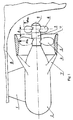
- the azimuth thruster disclosed by Fig. 1 comprises a streamlined strut or support 1 rotatably mounted relative to the hull of the vessel.
- a torpedo-shaped pod 2 is attached to the strut 1 and contains drive elements (not shown in the figure).
- a propeller drive shaft 3 is connected to the drive elements, and project outside from the pod 2.
- a screw propeller 4 is mounted on the overhanging part of the shaft 3 and inside a nozzle 5.
- the nozzle 5 is a hollow, tube like element (the nozzle is sectioned in figure 1) attached to the pod 2 by means of support arms or mounting brackets 7 and has an inlet 10 for the inflowing water and correspondingly an outlet for the outflowing water.
- the azimuth thruster as a whole is usually fitted in the rear end 8 of a vessel, but the thruster may also be fitted otherwise, such as in the forward end of the vessel.
- the skilled person is familiar with the above described basic members of an azimuthing propulsion system provided with a nozzle and the possible modifications and variations thereof as well, and these are thus not explained in more detail herein.
- the blades or vanes 6 are robustly constructed, i.e. they are made more solid than it is actually necessary for guiding the flow of water, so that they can effectively fulfill also the other basic functions thereof, namely breaking and/or throwing away the ice in front of the nozzle inlet.
- the diameter of the ice-breaking blades and vanes has to be chosen so that they can effectively perform their.basic functions: throwing away and breaking/crushing of ice and formation of flow before the nozzle.
- the blade diameter must be 1.5-2 times larger than that of the propeller hub 9.
- the upper limit of the blade (vane) diameter is, in turn, dictated by the need to avoid much heavier ice loads on the propeller shaft than what is the case when using an open screw propeller (i.e. no nozzle).
- the blades (vanes) will have to frequently mill the ice.
- ice anti-torque moment will be proportional to the blade diameter to the power 2-2.5 (see e.g.
- the ice-breaking blades or vanes 6 must be mounted fore of the nozzle inlet 10 and spaced from the fore edge i.e. the inlet 10 of the nozzle 5.
- the blades positioned in too close proximity to the nozzle inlet opening 10, ice casting away by the blades will be hindered by drawing in forces of the nozzle. In this case, all ice pieces in way of the nozzle inlet opening will be destroyed by milling which will, in turn, result to an undesired wasting of the shaft rotation energy and excessive loading of the shaft line.
- the blades cannot be mounted at a too great distance in front of the nozzle either since they will then loose their screw/nozzle protection capability.
- the inventors also found that in most cases it is preferred to position the ice-breaking blades or vanes uniformly in the plane perpendicular to that of the propeller shaft in order to eliminate inertial loads on the shaft line.
- the final diameter of the ice-breaking blades (vanes), their number and spacing from the nozzle fore edge for each particular vessel and navigation conditions should be selected on the basis of data obtained from tests in hydrodynamic and ice model basins.
- the curves (1), (2), (3) in this plot correspond to the values of K T ⁇ , K Q ⁇ and ⁇ p for the standard "screw-nozzle" propulsion unit.
- the curves (4), (5) and (6) show the values of K T ⁇ , K Q ⁇ and ⁇ p , respectively, for the proposed propulsive unit.
- a rotating screw propeller develops a thrust that drives the vessel. Owing to the nozzle the thrust is additionally increased by 20-25%. Blades and/or vanes dimensioned as stated above and which rotate together with the screw propeller cast away and/or destroy ice and prevent blocking of the nozzle inlet opening.
- the invention provides apparatus and a method by which a significant improvement is achieved in the area of propulsion systems. It should, however, be understood that the above description of an example of the invention is not meant to restrict the invention to the specific forms presented in this connection but rather the present invention is meant to cover all modifications, similarities and alternatives which are included in the spirit and scope of the present invention, as defined by the appended claims. For instance, upon reading the above description together with the annexed drawing it will be obvious to the skilled person to use this invention in connection with conventional propulsion units.
Landscapes
- Chemical & Material Sciences (AREA)
- Engineering & Computer Science (AREA)
- Combustion & Propulsion (AREA)
- Mechanical Engineering (AREA)
- Ocean & Marine Engineering (AREA)
- Earth Drilling (AREA)
- Mixers Of The Rotary Stirring Type (AREA)
- Control Of Position, Course, Altitude, Or Attitude Of Moving Bodies (AREA)
- Cleaning In General (AREA)
- Control Of Turbines (AREA)
- Vehicle Body Suspensions (AREA)
- Electrical Discharge Machining, Electrochemical Machining, And Combined Machining (AREA)
Claims (7)
- Antriebssystem umfassend:eine Antriebswelle;eine an der Antriebswelle angebrachte Antriebsschraube;eine die Antriebsschraube umgebende Düse, welche einen Wassereinlass und einen Wasserauslass hat; undan einem Bereich der Antriebswelle, der von dem Wassereinlass nach außen vorsteht angebrachte drehbare Blätter oder Schaufeln zum Brechen und/oder Zerkleinern von Eis bevor das Eis in die Düse eintritt, wobei der Punkte maximalen Durchmessers der Blätter oder Schaufeln einen Abstand von der Ebene des Wassereinlasses aufweist, der 0,02 bis 0,25 mal dem Durchmesser der Antriebsschraube entspricht, und wobei die drehbaren Blätter oder Schaufeln einen Durchmesser haben, der 0,6 bis 0,8 mal dem Durchmesser der Antriebsschraube entspricht.
- Antriebssystem nach Anspruch 1, wobei es eine Azimutantriebseinheit umfasst, welche für das Bewegen und Manövrieren eines Wasserfahrzeugs verwendet wird, welche Antriebseinheit eine Halterung zum drehbaren Verbinden der Antriebseinheit mit einem Wasserfahrzeug und ein mit der Halterung verbundenes Gehäuse, das Antriebselemente zum Drehen der Antriebswelle einschließt, umfasst, und wobei die Düse fest an dem Gehäuse angebracht ist.
- Antriebssystem nach Anspruch 1 oder 2, wobei die Blätter oder Schaufeln gleichmäßig über den Umfang in einer Ebene senkrecht zu der Antriebsschraubenwelle verteilt sind.
- Ein Azimutschuberzeuger für Wasserfahrzeugantrieb und Steuerung unter vereisten Bedingungen, umfassend:einer Halterung zum Verbinden des Schuberzeugers mit einem Wasserfahrzeug,ein Antriebselemente einschließendes Gehäuse,eine Antriebsschraubenwelle mit einer Schraube und Eisbrechelementen, die an einem vorstehenden Abschnitt der Welle montiert sind, der von einer Düse, die die Schraube umgibt, nach außen vorsteht,wobei die Eisbrechelemente in Form von Blättern oder Schaufeln ausgebildet sind, die vor der Schraube befestigt sind und dazu geeignet sind, Eis zu brechen und/oder zu zerkleinern, dadurch gekennzeichnet, dassdie Blätter oder Schaufeln, an ihren Punkten maximalen Durchmessers in einem Abstand von 0,02 bis 0,25 mal dem Schraubendurchmesser von dem Einlass der Düse angeordnet sind, und, dass die Durchmesser der Blätter oder Schaufeln derart gewählt sind, dass sie gleich 0,6 bis 0,8 mal dem Schraubendurchmesser entsprechen.
- Wasserfahrzeug-Azimutschuberzeuger nach Anspruch 4, dadurch gekennzeichnet, dass die Blätter oder Schaufeln der Eisbrechelemente gleichmäßig über dem Umfang in einer Ebene senkrecht zu der Schraubenwelle verteilt sind.
- Verfahren zum Bewegen eines Wasserfahrzeugs unter vereisten Bedingungen mittels eines Antriebssystems umfassend eine Antriebswelle, eine Antriebsschraube, die an der Antriebswelle angebracht ist, und eine Düse, die die Antriebsschraube umgibt, welche Düse einen Wassereinlass und einen Wasserauslass hat, umfassend
Brechen und/oder Zerkleinern des Eises bevor das Eis in die Düse eintritt mittels rotierbarer Blätter oder Schaufeln, die an einem Abschnitt der Antriebswelle angeordnet sind, der von dem Wassereinlass nach außen vorsteht, welche Blätter oder Schaufeln derart gestaltet sind, dass der Punkt maximalen Durchmessers der Blätter oder Schaufeln in einem axialen Abstand von der Ebene des Wassereinlasses angeordnet ist, der 0,02 bis 0,25 mal dem Durchmesser der Antriebsschraube entspricht und welche drehbaren Blätter oder Schaufel einen Durchmesser haben, der 0,6 bis 0,8 mal dem Durchmesser der Antriebsschraube entspricht. - Verfahren nach Anspruch 6, wobei das Wasserfahrzeug durch eine Azimutantriebseinheit bewegt und manövriert wird.
Applications Claiming Priority (3)
| Application Number | Priority Date | Filing Date | Title |
|---|---|---|---|
| RU97115318/28A RU2126762C1 (ru) | 1997-09-15 | 1997-09-15 | Судовая винторулевая колонка |
| RU97115318 | 1997-09-15 | ||
| PCT/FI1998/000725 WO1999014113A1 (en) | 1997-09-15 | 1998-09-15 | Propulsion system and method |
Publications (2)
| Publication Number | Publication Date |
|---|---|
| EP1015308A1 EP1015308A1 (de) | 2000-07-05 |
| EP1015308B1 true EP1015308B1 (de) | 2003-03-05 |
Family
ID=20197130
Family Applications (1)
| Application Number | Title | Priority Date | Filing Date |
|---|---|---|---|
| EP98945326A Expired - Lifetime EP1015308B1 (de) | 1997-09-15 | 1998-09-15 | Antriebssystem und verfahren |
Country Status (10)
| Country | Link |
|---|---|
| EP (1) | EP1015308B1 (de) |
| JP (1) | JP2001516675A (de) |
| KR (1) | KR20010015586A (de) |
| AT (1) | ATE233692T1 (de) |
| AU (1) | AU9267598A (de) |
| CA (1) | CA2303523A1 (de) |
| DE (1) | DE69811919D1 (de) |
| NO (1) | NO20001355L (de) |
| RU (1) | RU2126762C1 (de) |
| WO (1) | WO1999014113A1 (de) |
Cited By (1)
| Publication number | Priority date | Publication date | Assignee | Title |
|---|---|---|---|---|
| CN107108004A (zh) * | 2014-05-14 | 2017-08-29 | Abb 有限公司 | 推进单元 |
Families Citing this family (11)
| Publication number | Priority date | Publication date | Assignee | Title |
|---|---|---|---|---|
| KR20030025067A (ko) * | 2001-09-19 | 2003-03-28 | 정창호 | 석류 추출물을 함유하는 화장료 조성물 |
| FR2869586B1 (fr) * | 2004-04-30 | 2006-06-16 | Alstom Sa | Ensemble de propulsion pour navire, comprenant une nacelle destinee a une installation sous la carene du navire |
| CN103097238B (zh) * | 2010-07-12 | 2016-09-21 | 罗尔斯-罗伊斯股份公司 | 具有推进单元的海洋船舶 |
| EP2461142B1 (de) * | 2010-12-01 | 2015-08-19 | AGUSTAWESTLAND S.p.A. | Verfahren und System zur Berechnung des Abfluggewichts eines Flugzeugs |
| RU2622168C2 (ru) | 2012-02-07 | 2017-06-13 | Роллс-Ройс Аб | Движительная установка для морского судна и морское судно, содержащее движительную установку данного типа |
| CN105026259B (zh) * | 2013-02-08 | 2018-11-27 | 三星重工业株式会社 | 用于船舶的推进设备 |
| EP2808247B1 (de) * | 2013-05-29 | 2019-01-02 | ABB Schweiz AG | Antriebseinheit mit elektrischem Motor, wobei der Stator in einem Ring um den Propeller angebracht ist |
| KR101486060B1 (ko) * | 2013-09-24 | 2015-01-23 | 옥질표 | 반전 프로펠러를 이용한 선박 추진 장치 |
| WO2018083370A1 (en) * | 2016-11-03 | 2018-05-11 | Abb Oy | A propulsion unit |
| CN109018197B (zh) * | 2018-07-25 | 2020-05-05 | 中国船舶重工集团公司第七0四研究所 | 极地冰级船舶主推进系统设计方法 |
| KR102702351B1 (ko) | 2019-04-02 | 2024-09-03 | 한화오션 주식회사 | 결빙 방지 장치를 구비한 추진기 및 그를 포함하는 선박 |
Family Cites Families (4)
| Publication number | Priority date | Publication date | Assignee | Title |
|---|---|---|---|---|
| CA1176919A (en) * | 1980-10-24 | 1984-10-30 | Eric R. May | Propulsion of ships |
| GB2085827B (en) * | 1980-10-24 | 1984-05-16 | Stone Vickers Ltd | Improvements relating to the propulsion of ships |
| FI79991C (fi) * | 1986-04-29 | 1990-04-10 | Hollming Oy | Propelleranordning foer ett fartyg. |
| FI91513C (fi) * | 1989-09-18 | 1994-07-11 | Aquamaster Rauma Oy | Suulakepotkurilaite |
-
1997
- 1997-09-15 RU RU97115318/28A patent/RU2126762C1/ru not_active IP Right Cessation
-
1998
- 1998-09-15 AU AU92675/98A patent/AU9267598A/en not_active Abandoned
- 1998-09-15 CA CA002303523A patent/CA2303523A1/en not_active Abandoned
- 1998-09-15 EP EP98945326A patent/EP1015308B1/de not_active Expired - Lifetime
- 1998-09-15 WO PCT/FI1998/000725 patent/WO1999014113A1/en not_active Ceased
- 1998-09-15 DE DE69811919T patent/DE69811919D1/de not_active Expired - Lifetime
- 1998-09-15 KR KR1020007002691A patent/KR20010015586A/ko not_active Withdrawn
- 1998-09-15 AT AT98945326T patent/ATE233692T1/de not_active IP Right Cessation
- 1998-09-15 JP JP2000511678A patent/JP2001516675A/ja active Pending
-
2000
- 2000-03-15 NO NO20001355A patent/NO20001355L/no not_active Application Discontinuation
Cited By (2)
| Publication number | Priority date | Publication date | Assignee | Title |
|---|---|---|---|---|
| CN107108004A (zh) * | 2014-05-14 | 2017-08-29 | Abb 有限公司 | 推进单元 |
| EP3142921A4 (de) * | 2014-05-14 | 2017-12-06 | ABB Oy | Antriebseinheit |
Also Published As
| Publication number | Publication date |
|---|---|
| ATE233692T1 (de) | 2003-03-15 |
| EP1015308A1 (de) | 2000-07-05 |
| JP2001516675A (ja) | 2001-10-02 |
| KR20010015586A (ko) | 2001-02-26 |
| NO20001355D0 (no) | 2000-03-15 |
| AU9267598A (en) | 1999-04-05 |
| CA2303523A1 (en) | 1999-03-25 |
| WO1999014113A1 (en) | 1999-03-25 |
| NO20001355L (no) | 2000-05-15 |
| RU2126762C1 (ru) | 1999-02-27 |
| DE69811919D1 (de) | 2003-04-10 |
Similar Documents
| Publication | Publication Date | Title |
|---|---|---|
| EP1015308B1 (de) | Antriebssystem und verfahren | |
| US4370096A (en) | Marine propeller | |
| JP5307131B2 (ja) | 船舶の砕氷特性を改善する方法およびこの方法によって構成した船舶 | |
| CN105829202B (zh) | 用于优选地在浅覆冰水中操作的破冰船 | |
| US4427393A (en) | Propulsion of ships | |
| EP1817225B1 (de) | Antriebssystem für seefahrzeug | |
| RU2584038C2 (ru) | Морское судно, предназначенное для работы в льдистых водах | |
| WO2004067379A1 (en) | Steering and propulsion arrangement for ship | |
| US9926059B2 (en) | Ship propulsion arrangement | |
| US5660131A (en) | Icebreaker attachment | |
| KR101577195B1 (ko) | 큰 직경의 스크루 프로펠러를 선박에 제공하는 방법 및 큰 직경의 스크루 프로펠러를 갖는 선박 | |
| US4798547A (en) | Fuel efficient propulsor for outboard motors | |
| US20060079140A1 (en) | Watercraft | |
| AU2003292278B2 (en) | Arrangement in a propulsion system | |
| KR20090041908A (ko) | 쇄빙선의 추진 시스템 및 이를 위한 쇄빙선 형상 | |
| US8197292B2 (en) | Propulsion system for marine vessel | |
| JPS61268593A (ja) | 船舶用二重反転プロペラ推進装置 | |
| US6981902B1 (en) | Marine reaction thruster | |
| GB2085827A (en) | Improvements relating to the propulsion of ships | |
| CN105793155B (zh) | 水上推进装置 | |
| JPH0699892A (ja) | プロペラハブ渦抑制型船舵 | |
| RU2141431C1 (ru) | Движительный комплекс судна ледового плавания | |
| JPH06104471B2 (ja) | 船舶の推進装置 | |
| JPS61196891A (ja) | 氷海船舶用ノズル |
Legal Events
| Date | Code | Title | Description |
|---|---|---|---|
| PUAI | Public reference made under article 153(3) epc to a published international application that has entered the european phase |
Free format text: ORIGINAL CODE: 0009012 |
|
| 17P | Request for examination filed |
Effective date: 20000330 |
|
| AK | Designated contracting states |
Kind code of ref document: A1 Designated state(s): AT BE CH CY DE DK ES FI FR GB GR IE IT LI LU MC NL PT SE |
|
| GRAH | Despatch of communication of intention to grant a patent |
Free format text: ORIGINAL CODE: EPIDOS IGRA |
|
| GRAH | Despatch of communication of intention to grant a patent |
Free format text: ORIGINAL CODE: EPIDOS IGRA |
|
| GRAA | (expected) grant |
Free format text: ORIGINAL CODE: 0009210 |
|
| AK | Designated contracting states |
Designated state(s): AT BE CH CY DE DK ES FI FR GB GR IE IT LI LU MC NL PT SE |
|
| PG25 | Lapsed in a contracting state [announced via postgrant information from national office to epo] |
Ref country code: NL Free format text: LAPSE BECAUSE OF FAILURE TO SUBMIT A TRANSLATION OF THE DESCRIPTION OR TO PAY THE FEE WITHIN THE PRESCRIBED TIME-LIMIT Effective date: 20030305 Ref country code: LI Free format text: LAPSE BECAUSE OF FAILURE TO SUBMIT A TRANSLATION OF THE DESCRIPTION OR TO PAY THE FEE WITHIN THE PRESCRIBED TIME-LIMIT Effective date: 20030305 Ref country code: IT Free format text: LAPSE BECAUSE OF FAILURE TO SUBMIT A TRANSLATION OF THE DESCRIPTION OR TO PAY THE FEE WITHIN THE PRESCRIBED TIME-LIMIT;WARNING: LAPSES OF ITALIAN PATENTS WITH EFFECTIVE DATE BEFORE 2007 MAY HAVE OCCURRED AT ANY TIME BEFORE 2007. THE CORRECT EFFECTIVE DATE MAY BE DIFFERENT FROM THE ONE RECORDED. Effective date: 20030305 Ref country code: GR Free format text: LAPSE BECAUSE OF FAILURE TO SUBMIT A TRANSLATION OF THE DESCRIPTION OR TO PAY THE FEE WITHIN THE PRESCRIBED TIME-LIMIT Effective date: 20030305 Ref country code: FR Free format text: LAPSE BECAUSE OF NON-PAYMENT OF DUE FEES Effective date: 20030305 Ref country code: FI Free format text: LAPSE BECAUSE OF FAILURE TO SUBMIT A TRANSLATION OF THE DESCRIPTION OR TO PAY THE FEE WITHIN THE PRESCRIBED TIME-LIMIT Effective date: 20030305 Ref country code: CH Free format text: LAPSE BECAUSE OF FAILURE TO SUBMIT A TRANSLATION OF THE DESCRIPTION OR TO PAY THE FEE WITHIN THE PRESCRIBED TIME-LIMIT Effective date: 20030305 Ref country code: BE Free format text: LAPSE BECAUSE OF FAILURE TO SUBMIT A TRANSLATION OF THE DESCRIPTION OR TO PAY THE FEE WITHIN THE PRESCRIBED TIME-LIMIT Effective date: 20030305 Ref country code: AT Free format text: LAPSE BECAUSE OF FAILURE TO SUBMIT A TRANSLATION OF THE DESCRIPTION OR TO PAY THE FEE WITHIN THE PRESCRIBED TIME-LIMIT Effective date: 20030305 |
|
| REG | Reference to a national code |
Ref country code: GB Ref legal event code: FG4D |
|
| REG | Reference to a national code |
Ref country code: CH Ref legal event code: EP |
|
| REG | Reference to a national code |
Ref country code: IE Ref legal event code: FG4D |
|
| REF | Corresponds to: |
Ref document number: 69811919 Country of ref document: DE Date of ref document: 20030410 Kind code of ref document: P |
|
| PG25 | Lapsed in a contracting state [announced via postgrant information from national office to epo] |
Ref country code: SE Free format text: LAPSE BECAUSE OF FAILURE TO SUBMIT A TRANSLATION OF THE DESCRIPTION OR TO PAY THE FEE WITHIN THE PRESCRIBED TIME-LIMIT Effective date: 20030605 Ref country code: PT Free format text: LAPSE BECAUSE OF FAILURE TO SUBMIT A TRANSLATION OF THE DESCRIPTION OR TO PAY THE FEE WITHIN THE PRESCRIBED TIME-LIMIT Effective date: 20030605 Ref country code: DK Free format text: LAPSE BECAUSE OF FAILURE TO SUBMIT A TRANSLATION OF THE DESCRIPTION OR TO PAY THE FEE WITHIN THE PRESCRIBED TIME-LIMIT Effective date: 20030605 |
|
| PG25 | Lapsed in a contracting state [announced via postgrant information from national office to epo] |
Ref country code: DE Free format text: LAPSE BECAUSE OF FAILURE TO SUBMIT A TRANSLATION OF THE DESCRIPTION OR TO PAY THE FEE WITHIN THE PRESCRIBED TIME-LIMIT Effective date: 20030606 |
|
| NLV1 | Nl: lapsed or annulled due to failure to fulfill the requirements of art. 29p and 29m of the patents act | ||
| PG25 | Lapsed in a contracting state [announced via postgrant information from national office to epo] |
Ref country code: LU Free format text: LAPSE BECAUSE OF NON-PAYMENT OF DUE FEES Effective date: 20030915 Ref country code: IE Free format text: LAPSE BECAUSE OF NON-PAYMENT OF DUE FEES Effective date: 20030915 Ref country code: GB Free format text: LAPSE BECAUSE OF NON-PAYMENT OF DUE FEES Effective date: 20030915 Ref country code: CY Free format text: LAPSE BECAUSE OF FAILURE TO SUBMIT A TRANSLATION OF THE DESCRIPTION OR TO PAY THE FEE WITHIN THE PRESCRIBED TIME-LIMIT Effective date: 20030915 |
|
| REG | Reference to a national code |
Ref country code: CH Ref legal event code: PL |
|
| PG25 | Lapsed in a contracting state [announced via postgrant information from national office to epo] |
Ref country code: MC Free format text: LAPSE BECAUSE OF NON-PAYMENT OF DUE FEES Effective date: 20030930 Ref country code: ES Free format text: LAPSE BECAUSE OF FAILURE TO SUBMIT A TRANSLATION OF THE DESCRIPTION OR TO PAY THE FEE WITHIN THE PRESCRIBED TIME-LIMIT Effective date: 20030930 |
|
| PLBE | No opposition filed within time limit |
Free format text: ORIGINAL CODE: 0009261 |
|
| STAA | Information on the status of an ep patent application or granted ep patent |
Free format text: STATUS: NO OPPOSITION FILED WITHIN TIME LIMIT |
|
| EN | Fr: translation not filed | ||
| 26N | No opposition filed |
Effective date: 20031208 |
|
| GBPC | Gb: european patent ceased through non-payment of renewal fee |
Effective date: 20030915 |
|
| REG | Reference to a national code |
Ref country code: IE Ref legal event code: MM4A |