EP1015827B2 - Installation pour la decomposition a basse temperature de l'air - Google Patents
Installation pour la decomposition a basse temperature de l'air Download PDFInfo
- Publication number
- EP1015827B2 EP1015827B2 EP98941421A EP98941421A EP1015827B2 EP 1015827 B2 EP1015827 B2 EP 1015827B2 EP 98941421 A EP98941421 A EP 98941421A EP 98941421 A EP98941421 A EP 98941421A EP 1015827 B2 EP1015827 B2 EP 1015827B2
- Authority
- EP
- European Patent Office
- Prior art keywords
- rectification column
- heat exchanger
- elements
- installation according
- insulation chamber
- Prior art date
- Legal status (The legal status is an assumption and is not a legal conclusion. Google has not performed a legal analysis and makes no representation as to the accuracy of the status listed.)
- Expired - Lifetime
Links
- 238000009434 installation Methods 0.000 title claims abstract description 19
- 238000000926 separation method Methods 0.000 title abstract description 8
- IJGRMHOSHXDMSA-UHFFFAOYSA-N Atomic nitrogen Chemical compound N#N IJGRMHOSHXDMSA-UHFFFAOYSA-N 0.000 claims description 36
- 238000009413 insulation Methods 0.000 claims description 21
- 229910052757 nitrogen Inorganic materials 0.000 claims description 18
- QVGXLLKOCUKJST-UHFFFAOYSA-N atomic oxygen Chemical compound [O] QVGXLLKOCUKJST-UHFFFAOYSA-N 0.000 claims description 15
- 239000001301 oxygen Substances 0.000 claims description 15
- 229910052760 oxygen Inorganic materials 0.000 claims description 15
- 239000000463 material Substances 0.000 claims description 11
- 239000011810 insulating material Substances 0.000 claims description 4
- 235000019362 perlite Nutrition 0.000 claims description 4
- 239000010451 perlite Substances 0.000 claims description 4
- 238000005194 fractionation Methods 0.000 claims 2
- 239000007788 liquid Substances 0.000 description 13
- 238000000354 decomposition reaction Methods 0.000 description 5
- 239000007789 gas Substances 0.000 description 5
- 238000002955 isolation Methods 0.000 description 5
- 229910052751 metal Inorganic materials 0.000 description 3
- 239000002184 metal Substances 0.000 description 3
- 229910001220 stainless steel Inorganic materials 0.000 description 3
- 239000010935 stainless steel Substances 0.000 description 3
- 229910052782 aluminium Inorganic materials 0.000 description 2
- XAGFODPZIPBFFR-UHFFFAOYSA-N aluminium Chemical compound [Al] XAGFODPZIPBFFR-UHFFFAOYSA-N 0.000 description 2
- 239000011152 fibreglass Substances 0.000 description 2
- 238000004519 manufacturing process Methods 0.000 description 2
- 229910000831 Steel Inorganic materials 0.000 description 1
- 229910000746 Structural steel Inorganic materials 0.000 description 1
- 238000005452 bending Methods 0.000 description 1
- 230000006835 compression Effects 0.000 description 1
- 238000007906 compression Methods 0.000 description 1
- 239000000470 constituent Substances 0.000 description 1
- 238000012856 packing Methods 0.000 description 1
- 239000004810 polytetrafluoroethylene Substances 0.000 description 1
- 229920001343 polytetrafluoroethylene Polymers 0.000 description 1
- 238000011084 recovery Methods 0.000 description 1
- 238000005057 refrigeration Methods 0.000 description 1
- 239000010959 steel Substances 0.000 description 1
Images
Classifications
-
- F—MECHANICAL ENGINEERING; LIGHTING; HEATING; WEAPONS; BLASTING
- F25—REFRIGERATION OR COOLING; COMBINED HEATING AND REFRIGERATION SYSTEMS; HEAT PUMP SYSTEMS; MANUFACTURE OR STORAGE OF ICE; LIQUEFACTION SOLIDIFICATION OF GASES
- F25J—LIQUEFACTION, SOLIDIFICATION OR SEPARATION OF GASES OR GASEOUS OR LIQUEFIED GASEOUS MIXTURES BY PRESSURE AND COLD TREATMENT OR BY BRINGING THEM INTO THE SUPERCRITICAL STATE
- F25J3/00—Processes or apparatus for separating the constituents of gaseous or liquefied gaseous mixtures involving the use of liquefaction or solidification
- F25J3/02—Processes or apparatus for separating the constituents of gaseous or liquefied gaseous mixtures involving the use of liquefaction or solidification by rectification, i.e. by continuous interchange of heat and material between a vapour stream and a liquid stream
- F25J3/04—Processes or apparatus for separating the constituents of gaseous or liquefied gaseous mixtures involving the use of liquefaction or solidification by rectification, i.e. by continuous interchange of heat and material between a vapour stream and a liquid stream for air
- F25J3/04763—Start-up or control of the process; Details of the apparatus used
- F25J3/04866—Construction and layout of air fractionation equipments, e.g. valves, machines
- F25J3/04945—Details of internal structure; insulation and housing of the cold box
-
- F—MECHANICAL ENGINEERING; LIGHTING; HEATING; WEAPONS; BLASTING
- F25—REFRIGERATION OR COOLING; COMBINED HEATING AND REFRIGERATION SYSTEMS; HEAT PUMP SYSTEMS; MANUFACTURE OR STORAGE OF ICE; LIQUEFACTION SOLIDIFICATION OF GASES
- F25J—LIQUEFACTION, SOLIDIFICATION OR SEPARATION OF GASES OR GASEOUS OR LIQUEFIED GASEOUS MIXTURES BY PRESSURE AND COLD TREATMENT OR BY BRINGING THEM INTO THE SUPERCRITICAL STATE
- F25J3/00—Processes or apparatus for separating the constituents of gaseous or liquefied gaseous mixtures involving the use of liquefaction or solidification
- F25J3/02—Processes or apparatus for separating the constituents of gaseous or liquefied gaseous mixtures involving the use of liquefaction or solidification by rectification, i.e. by continuous interchange of heat and material between a vapour stream and a liquid stream
- F25J3/04—Processes or apparatus for separating the constituents of gaseous or liquefied gaseous mixtures involving the use of liquefaction or solidification by rectification, i.e. by continuous interchange of heat and material between a vapour stream and a liquid stream for air
- F25J3/04248—Generation of cold for compensating heat leaks or liquid production, e.g. by Joule-Thompson expansion
- F25J3/04254—Generation of cold for compensating heat leaks or liquid production, e.g. by Joule-Thompson expansion using the cold stored in external cryogenic fluids
-
- F—MECHANICAL ENGINEERING; LIGHTING; HEATING; WEAPONS; BLASTING
- F25—REFRIGERATION OR COOLING; COMBINED HEATING AND REFRIGERATION SYSTEMS; HEAT PUMP SYSTEMS; MANUFACTURE OR STORAGE OF ICE; LIQUEFACTION SOLIDIFICATION OF GASES
- F25J—LIQUEFACTION, SOLIDIFICATION OR SEPARATION OF GASES OR GASEOUS OR LIQUEFIED GASEOUS MIXTURES BY PRESSURE AND COLD TREATMENT OR BY BRINGING THEM INTO THE SUPERCRITICAL STATE
- F25J3/00—Processes or apparatus for separating the constituents of gaseous or liquefied gaseous mixtures involving the use of liquefaction or solidification
- F25J3/02—Processes or apparatus for separating the constituents of gaseous or liquefied gaseous mixtures involving the use of liquefaction or solidification by rectification, i.e. by continuous interchange of heat and material between a vapour stream and a liquid stream
- F25J3/04—Processes or apparatus for separating the constituents of gaseous or liquefied gaseous mixtures involving the use of liquefaction or solidification by rectification, i.e. by continuous interchange of heat and material between a vapour stream and a liquid stream for air
- F25J3/044—Processes or apparatus for separating the constituents of gaseous or liquefied gaseous mixtures involving the use of liquefaction or solidification by rectification, i.e. by continuous interchange of heat and material between a vapour stream and a liquid stream for air using a single pressure main column system only
-
- F—MECHANICAL ENGINEERING; LIGHTING; HEATING; WEAPONS; BLASTING
- F25—REFRIGERATION OR COOLING; COMBINED HEATING AND REFRIGERATION SYSTEMS; HEAT PUMP SYSTEMS; MANUFACTURE OR STORAGE OF ICE; LIQUEFACTION SOLIDIFICATION OF GASES
- F25J—LIQUEFACTION, SOLIDIFICATION OR SEPARATION OF GASES OR GASEOUS OR LIQUEFIED GASEOUS MIXTURES BY PRESSURE AND COLD TREATMENT OR BY BRINGING THEM INTO THE SUPERCRITICAL STATE
- F25J3/00—Processes or apparatus for separating the constituents of gaseous or liquefied gaseous mixtures involving the use of liquefaction or solidification
- F25J3/02—Processes or apparatus for separating the constituents of gaseous or liquefied gaseous mixtures involving the use of liquefaction or solidification by rectification, i.e. by continuous interchange of heat and material between a vapour stream and a liquid stream
- F25J3/04—Processes or apparatus for separating the constituents of gaseous or liquefied gaseous mixtures involving the use of liquefaction or solidification by rectification, i.e. by continuous interchange of heat and material between a vapour stream and a liquid stream for air
- F25J3/04763—Start-up or control of the process; Details of the apparatus used
- F25J3/04866—Construction and layout of air fractionation equipments, e.g. valves, machines
- F25J3/04872—Vertical layout of cold equipments within in the cold box, e.g. columns, heat exchangers etc.
-
- F—MECHANICAL ENGINEERING; LIGHTING; HEATING; WEAPONS; BLASTING
- F25—REFRIGERATION OR COOLING; COMBINED HEATING AND REFRIGERATION SYSTEMS; HEAT PUMP SYSTEMS; MANUFACTURE OR STORAGE OF ICE; LIQUEFACTION SOLIDIFICATION OF GASES
- F25J—LIQUEFACTION, SOLIDIFICATION OR SEPARATION OF GASES OR GASEOUS OR LIQUEFIED GASEOUS MIXTURES BY PRESSURE AND COLD TREATMENT OR BY BRINGING THEM INTO THE SUPERCRITICAL STATE
- F25J3/00—Processes or apparatus for separating the constituents of gaseous or liquefied gaseous mixtures involving the use of liquefaction or solidification
- F25J3/02—Processes or apparatus for separating the constituents of gaseous or liquefied gaseous mixtures involving the use of liquefaction or solidification by rectification, i.e. by continuous interchange of heat and material between a vapour stream and a liquid stream
- F25J3/04—Processes or apparatus for separating the constituents of gaseous or liquefied gaseous mixtures involving the use of liquefaction or solidification by rectification, i.e. by continuous interchange of heat and material between a vapour stream and a liquid stream for air
- F25J3/04763—Start-up or control of the process; Details of the apparatus used
- F25J3/04866—Construction and layout of air fractionation equipments, e.g. valves, machines
- F25J3/0489—Modularity and arrangement of parts of the air fractionation unit, in particular of the cold box, e.g. pre-fabrication, assembling and erection, dimensions, horizontal layout "plot"
-
- F—MECHANICAL ENGINEERING; LIGHTING; HEATING; WEAPONS; BLASTING
- F25—REFRIGERATION OR COOLING; COMBINED HEATING AND REFRIGERATION SYSTEMS; HEAT PUMP SYSTEMS; MANUFACTURE OR STORAGE OF ICE; LIQUEFACTION SOLIDIFICATION OF GASES
- F25J—LIQUEFACTION, SOLIDIFICATION OR SEPARATION OF GASES OR GASEOUS OR LIQUEFIED GASEOUS MIXTURES BY PRESSURE AND COLD TREATMENT OR BY BRINGING THEM INTO THE SUPERCRITICAL STATE
- F25J2210/00—Processes characterised by the type or other details of the feed stream
- F25J2210/42—Nitrogen
Definitions
- the invention relates to a plant for cryogenic separation of air, having at least one rectification column, which is connected to an air line for supplying decomposition air, with a nitrogen line for withdrawing a nitrogen fraction, with an oxygen line for extracting an oxygen fraction and surrounded by at least one insulating jacket, the one Insulating space limited, through which the lines are guided to the rectification column and to which the rectification column is connected.
- Systems for the cryogenic separation of air consist essentially of one or more rectification columns whose function is to decompose the cooled in a heat exchanger to about minus 170 ° C air into its constituents.
- the separation may take place in a rectification column.
- the oxygen-rich fraction is withdrawn liquid in the bottom of the column and evaporated in the condenser.
- gaseous pure nitrogen is withdrawn to recover it as a product and a second part is liquefied in the condenser.
- liquid nitrogen is fed from a storage tank into the column.
- the storage tank is charged from an external source with liquid nitrogen.
- Storage tank and rectification column are arranged side by side.
- the storage tank for liquid nitrogen is isolated by a vacuum container which engages around the outer shell of the storage container and whose evacuated between the inner and outer container insulation space is evacuated.
- the deep-cold rectification column is installed in a metal jacket whose free space is filled with insulating material. Internationally, the name “cold box” has come to be used.
- connection of the rectification column with the metal jacket takes place via rigid elements which form a fixed bearing on the side directed towards the bottom.
- the elements are attached to the rectification column and / or the metal jacket releasably or permanently.
- the rectification column stands on the elements while the opposite end is fixed in the isolation space.
- fixing elements and / or transport securing elements are provided adjacent to the free end of the rectification column, which support the free end of the rectification column on the insulating jacket, so that the rectification column is fixed at the free end in the operating position and can be transported in the horizontal.
- the elements are rigidly connected to the insulating jacket and the rectification column.
- the fasteners have a high weight and deteriorate due to heat conduction, the heat balance of the system.
- the invention has for its object to provide a system for cryogenic separation of air, in which for transport and operation without assembly / demotage of parts of the cold box, the fixation of the rectification column can be simplified.
- the invention enables a much simpler attachment of arranged in the isolation room equipment parts, such as rectifying and possibly heat exchangers, since these are arranged in the isolation room equipment parts are connected via cable-shaped guy elements with the insulating jacket, which hold the equipment parts in the insulation space in a predetermined position. At the same time, the rope-shaped elements take over the fixation and transport securing of the rectification column and possibly the heat exchanger.
- Flexible rope-shaped elements are understood to mean cables, chains, tie rods and the like which clamp at least the rectification column in the insulating jacket.
- the rope-shaped elements are connected at their one end to the rectification column and, if appropriate, the heat exchanger via clamps which annularly surround the rectification column and possibly the heat exchanger at its circumference in order to absorb the tensile forces occurring during the tensioning.
- the clamps are in accordance with customary tolerances on the rectification column on; if necessary, intermediate layers of PTFE can be provided between the rectification column and the clamps. They have U-shaped connecting elements on which the rope-shaped elements are attached. The attachment and replacement of the rope-shaped elements is so easy to make.
- the clamps are made of a material having a lower réelledehnugswert than the material of the rectification column and possibly of the heat exchanger.
- the material of the clamps is stainless steel, the material of the rectification column is aluminum.
- the Werksoff the rectification column shrinks at operating temperatures of ca, -170 ° C more than the material of the clamps, which allows a change in the dimensions of the rectification column, in particular in length.
- the rope-shaped elements act as transport securing elements, which allow a transport of the cold box in the horizontal without the rectification column and possibly the heat exchanger subject to a significant bending stress.
- the cold box can be fully assembled by the manufacturer and transported in a horizontal position to the operator of the system at ambient temperature and operated without disassembly of parts of the system.
- the rope-shaped elements absorb the thermal expansion of insulating jacket and rectification column and possibly heat exchangers, which are present due to the different temperatures of the system components in the various operating conditions (in operation / out of service).
- each rope-shaped element consists of a rope whose ends are designed as eye terminals, which are mounted in terminals.
- each rope-shaped element can be adjusted in its length.
- the bearings are insulated with insulating materials such as glass fiber reinforced plastic (GRP) between the bearing and the inner surface of the insulating sheath arranged as intermediate layers.
- GRP glass fiber reinforced plastic
- the insulation space with insulating material for. B. "Perlite", filled with a density between 40 to 80 kg / m 3 .
- An optimized heat balance of the heat exchanger can be achieved within the insulation space in that the heat exchanger with the side into which the decomposition air and the product streams emerge and which is at a temperature level of about plus 10 ° C, the insulating jacket inclined and thus in is located in the immediate vicinity of the warmer Isoliermantels, while the Zerlegungs Kunststoffaus- and the product flow entry is located in the vicinity of the rectification column, so that lying at a temperature level of about minus 170 ° C side of the heat exchanger of the lying at about the same or similar temperature level rectification column inclined is.
- the heat balance of the installation is substantially optimized by the insulation and the arrangement of the installation parts and rectification column, so that the expansion of the installation parts is reduced.
- the fixation of the heat exchanger at an angle by means of projecting described rope-shaped elements is particularly easy to achieve.
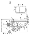
- the essential parts of the system for the cryogenic separation of air are shown schematically in FIG.
- the plant consists essentially of a liquid gas tank 10, a rectification column 15 with top condenser 16 and a heat exchanger 17.
- the figure is not to scale, a rectification column 15 is in relation to the liquid gas tank 10 usually much higher than that shown.
- the liquid gas container 10 for the liquefied gas 11 consists in the usual way of an inner container 12 and an outer container 13, the intermediate space 14 is powder-vacuum insulated.
- Rectification column 15 with top condenser 16 and heat exchanger 17 are surrounded by an insulating jacket 18.
- the insulating jacket is made of unalloyed structural steel and encloses rectification column 15 with top condenser 16 and heat exchanger 17.
- the insulating space surrounded by the insulating jacket 18 23 is provided with insulating means, for. B. Perlite filled out.
- the perlite fill all the cavities of the insulation space 23 and surround the rectification column 15 with the top condenser 16, the heat exchanger 17 and all arranged in the insulation space 23 further components, such as piping, control valves and like.
- the rectification column 15 stands on bearings 24 formed as feet and connected to the insulating jacket 18.
- the bearings 24 receive the weighting forces of the rectification column.
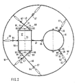
- the rectification column with rope-shaped elements 20, 21, 22, 25, 26 is laterally braced.
- Rope-shaped elements can be all elements, such as stainless steel ropes, chains, tie rods and the like, if they are suitable for tensioning the rectification column 15.
- the rectification column is braced at least on three sides (120 °) with ropes adjustable in length via adjusting elements 60, 61, 66.
- the adjusting elements 60, 61, 66 each consist of a threaded rod 62 connected to the insulating jacket 18, which is screwed into a nut 63 with left / right-hand thread. From the other side, a U-shaped terminal 64 is screwed into the nut 63 by means of a threaded rod attached thereto. As the nut 63 rotates, the threaded rods move toward or away from each other.
- the rope-shaped element 26 mounted and fastened in the terminal 64 is correspondingly pulled in the direction of the insulating jacket 18 or relaxed towards the rectification column.
- the rope-shaped elements 20, 21, 22, 25, 26 are mounted on the side facing the rectification column 15 in stationary terminals 65.
- the stationary terminals 65 are attached to clamps 19, 51 which annularly surround the rectification column 15 at its periphery.
- the clamps 19, 51 with the rope-shaped elements 20, 21, 22, 25, 26 surround the rectification column 15 adjacent to the bearing 24 opposite end.
- the clamps are made of a material, such as stainless steel, which has a lower thermal expansion value than the material, for example aluminum, the rectification column.
- a clearance between the clamps 19, 51 and the rectification column 15 arises due to the different thermal expansion values of the materials at the low operating temperatures, which permits a change in dimension, in particular a change in the length of the rectification column.
- the heat exchanger 17 is arranged in the insulation space 23, which is supplied via line 28 compressed and purified air.
- the cold air is blown into the lower portion of the rectification column 15.
- the rectification column 15 is operated under a pressure of 4.5 to 12 bar, preferably about 6 bar. It is equipped in the embodiment with two sections 29, 30 of parent packs or trays. Above the packing sections 29, 30, a liquid collector and distributor 31, 32 is provided in each case.
- Oxygen-enriched bottoms liquid can be withdrawn via an oxygen line 33.
- a nitrogen line 34 discharges gaseous nitrogen as a product through the heat exchanger 17.
- In the upper part of the rectification column 15 also opens a first feed line 35, directly into the upper liquid receiver 31. It is used for supply and removal of liquid nitrogen and connects the interiors of rectification column 15 and nitrogen tank 10th
- a top condenser 16 is used to liquefy nitrogen at the top of the rectification column 15.
- the indicated in the drawing passages are open to the interior of the rectification column and thus form the nitrogen passages.
- oxygen-enriched liquid which is introduced via the oxygen line 33. It evaporates in direct heat exchange with condensing nitrogen.
- the vaporized fraction is removed via an oxygen product line 36 and warmed in the heat exchanger 17 against decomposition air 28.
- the heat exchanger 17 is secured with two support brackets 37 on the insulating jacket 18.
- the support brackets are assigned to the warm end (+ 10 ° C) of the heat exchanger 17 and carry the vertical loads of this.
- the heat exchanger 17 is arranged in the insulation space that the oxygen product input 38 is further away from the insulating jacket, as the oxygen product output 39.
- the heat exchanger 17 at an angle 70 between 3 and 10 degrees, preferably at an angle of 5 degrees with its cold End (about - 170 ° C) is arranged inclined to the rectification column, the refrigeration demand is reduced because the warm end of the warmer insulating jacket 18 and the cold end of the heat exchanger of the rectification column is assigned.
- rope-shaped elements 40, 41, 46, 47 which are formed as a cable tension.
- the rope-shaped elements 40, 41, 46, 47 are formed according to the rope-shaped elements described in connection with the cable tension of the rectification column.
- the ropes 40, 41, 46, 47 terminate in eyebolts 67, 68 which are mounted in U-shaped adjustable and stationary terminals 64, 65.
- the rope-shaped elements 46, 47 and 40, 41 extend crosswise at an angle 71 of 45 ° to the longitudinal axis 72 of the heat exchanger 17.
- the rope-shaped elements 40, 41, 46, 47 are attached to the heat exchanger 17 by means of clamps 50.
- valve 42 The level of the column sump of the rectification column is controlled by means of a valve 42, which is arranged in the oxygen line 33.
- Valve 42 is disposed within the insulation space 23 and powder-insulated.
- the adjusting device 44 for example, a control valve spindle, passed through the insulating jacket 18 to the outside and connected to a drive 45 so that the valve is adjustable from the outside.
Landscapes
- Engineering & Computer Science (AREA)
- Physics & Mathematics (AREA)
- Mechanical Engineering (AREA)
- Thermal Sciences (AREA)
- General Engineering & Computer Science (AREA)
- Separation By Low-Temperature Treatments (AREA)
- Control And Other Processes For Unpacking Of Materials (AREA)
- Processing Of Solid Wastes (AREA)
Claims (12)
- Installation pour la décomposition de l'air à basse température comprenant au moins une colonne de rectification, reliée à une conduite d'air pour l'alimentation en air à décomposer, une conduite d'azote pour extraire la fraction d'azote, une conduite d'oxygène pour extraire la fraction d'oxygène, et entourée par au moins une enveloppe isolante qui délimite une enceinte isolée à travers laquelle passent les conduites reliées à la colonne de rectification,
caractérisée en ce que
sur son étendu longitudinale la colonne de rectification (15) est serrée dans l'enceinte isolée (23) à l'aide d'éléments (20, 21, 22, 25, 26, 40, 41) en forme de câbles perpendiculaires à l'étendue longitudinale de façon à se trouver dans une position prédéterminée, et les éléments (20, 21, 22, 25, 26) sont reliés par une extrémité à la colonne de rectification par des moyens (51, 19), notamment des colliers, qui entourent la colonne de rectification (15) au niveau de sa périphérie de manière annulaire, et qui comportent des éléments de liaison auxquels sont fixés les éléments (20, 21, 22, 25, 26). - Installation selon la revendication 1,
caractérisée en ce que
la colonne de rectification (15) comporte un condenseur de tête (16) installé dans l'enceinte isolée (23), relié du côté de la sortie par une conduite de production d'oxygène (36) à un échangeur de chaleur (17), et du côté de l'entrée par une conduite d'oxygène (33) installée dans l'enceinte d'isolée (23) à la zone inférieure de la colonne de rectification (15). - Installation selon la revendication 2,
caractérisée en ce que
l'échangeur de chaleur (17) est installé dans l'enceinte isolée (23). - Installation selon l'une des revendications 2 à 3,
caractérisée en ce que
l'échangeur de chaleur (17) est mis en tension dans l'enceinte isolée (23) avec des éléments en forme de câbles (40, 41) pour se trouver dans une position prédéterminée. - Installation selon la revendication 4,
caractérisée en ce que
les éléments (40, 41) ont une extrémité reliée à l'échangeur de chaleur par des moyens (50), notamment des colliers qui entourent la périphérie de l'échangeur de manière annulaire, et qui ont des éléments de liaison sur lesquels se fixent les éléments (40, 41). - Installation selon l'une quelconque des revendications 1 à 5,
caractérisée en ce que les moyens (50, 51, 19) sont en un matériau ayant un coefficient de dilatation thermique plus faible que celui du matériau de la colonne de rectification (15) et/ou de l'échangeur de chaleur. - Installation selon l'une quelconque des revendications 5 ou 6,
caractérisée en ce que
lorsque l'installation fonctionne, un espace libre situé entre les moyens (50, 51, 19) et la colonne de rectification (15) et/ou l'échangeur de chaleur (17), permet une modification des dimensions de la colonne de rectification (15) et/ou de l'échangeur de chaleur (17). - Installation selon l'une quelconque des revendications 1 à 5,
caractérisée en ce que
les éléments (20, 21, 22, 25, 26, 40, 41) sont fixés par leur autre extrémité à l'enveloppe isolante (18), et l'enveloppe isolante (18) comporte des paliers (24, 37) qui reçoivent la charge de la colonne de rectification (15) et/ou de l'échangeur de chaleur (17) en fonctionnement. - Installation selon l'une quelconque des revendications 1 à 8,
caractérisée en ce que les éléments (20, 21, 22, 25, 26 ; 40, 41) sont de longueur réglable par des éléments de réglage (60, 61, 66) . - Installation selon l'une quelconque des revendications 2 à 9,
caractérisée en ce que
l'échangeur de chaleur (17) est disposé incliné dans l'enceinte isolée (23) suivant un angle (70) pour que l'extrémité froide (environ -175°C) de l'échangeur de chaleur se trouve à proximité de la colonne de rectification (15) et l'extrémité chaude (environ +10°C) à proximité de l'enveloppe isolante (18). - Installation selon l'une quelconque des revendications 2 à 10,
caractérisée en ce que
l'échangeur de chaleur (17) est incliné suivant un angle compris entre 1 et 45° dans l'enceinte isolée (23). - Installation selon l'une quelconque des revendications 1 à 11,
caractérisée en ce que
l'enceinte isolée (23) est remplie de matériau isolant, par exemple de la perlite.
Applications Claiming Priority (3)
| Application Number | Priority Date | Filing Date | Title |
|---|---|---|---|
| DE19737520 | 1997-08-28 | ||
| DE19737520A DE19737520A1 (de) | 1997-08-28 | 1997-08-28 | Anlage zur Tieftemperaturzerlegung von Luft |
| PCT/EP1998/005182 WO1999011991A1 (fr) | 1997-08-28 | 1998-08-17 | Installation pour la decomposition a basse temperature de l'air |
Publications (3)
| Publication Number | Publication Date |
|---|---|
| EP1015827A1 EP1015827A1 (fr) | 2000-07-05 |
| EP1015827B1 EP1015827B1 (fr) | 2002-11-13 |
| EP1015827B2 true EP1015827B2 (fr) | 2007-07-11 |
Family
ID=7840453
Family Applications (1)
| Application Number | Title | Priority Date | Filing Date |
|---|---|---|---|
| EP98941421A Expired - Lifetime EP1015827B2 (fr) | 1997-08-28 | 1998-08-17 | Installation pour la decomposition a basse temperature de l'air |
Country Status (5)
| Country | Link |
|---|---|
| EP (1) | EP1015827B2 (fr) |
| AT (1) | ATE227829T1 (fr) |
| CZ (1) | CZ294901B6 (fr) |
| DE (2) | DE19737520A1 (fr) |
| WO (1) | WO1999011991A1 (fr) |
Cited By (1)
| Publication number | Priority date | Publication date | Assignee | Title |
|---|---|---|---|---|
| US20200248872A1 (en) * | 2016-12-29 | 2020-08-06 | L'air Liquide, Societe Anonyme Pour I'etude Et I'exploitation Des Procedes Georges Claude | Process and apparatus for establishing vacuum insulation under cryogenic condition |
Families Citing this family (6)
| Publication number | Priority date | Publication date | Assignee | Title |
|---|---|---|---|---|
| FR2805603B1 (fr) * | 2000-02-25 | 2002-05-31 | Air Liquide | Structure d'installation, notamment cryogenique, comportant des elements dont les variations dimensionnelles dues a des changements de temperature sont synchronisees |
| GB2398516A (en) * | 2003-02-18 | 2004-08-25 | Air Prod & Chem | Distillation column with a surrounding insulating support structure |
| DE10319755A1 (de) * | 2003-04-30 | 2004-11-18 | Linde Ag | Kolonnensystem und Verfahren zu dessen Herstellung |
| ATE326672T1 (de) * | 2003-04-30 | 2006-06-15 | Linde Ag | Kolonnensystem und verfahren zu dessen herstellung |
| EP2030662A1 (fr) * | 2007-08-09 | 2009-03-04 | L'AIR LIQUIDE, Société Anonyme pour l'Etude et l'Exploitation des Procédés Georges Claude | Dispositif de support pour une colonne de distillation dans une enceinte isolée |
| WO2019144380A1 (fr) * | 2018-01-26 | 2019-08-01 | L'air Liquide, Societe Anonyme Pour L'etude Et L'exploitation Des Procedes Georges Claude | Unité de séparation d'air par distillation cryogénique |
Citations (3)
| Publication number | Priority date | Publication date | Assignee | Title |
|---|---|---|---|---|
| US2916179A (en) † | 1958-01-13 | 1959-12-08 | British Oxygen Co Ltd | Thermally insulated storage vessels |
| DE4135302A1 (de) † | 1991-10-25 | 1993-04-29 | Linde Ag | Anlage zur tieftemperaturzerlegung von luft |
| JPH09137627A (ja) † | 1995-11-14 | 1997-05-27 | Ishikawajima Harima Heavy Ind Co Ltd | 二重殻平底円筒タンクの滑動防止装置 |
Family Cites Families (1)
| Publication number | Priority date | Publication date | Assignee | Title |
|---|---|---|---|---|
| FR2668256B1 (fr) * | 1990-10-18 | 1992-12-11 | Air Liquide | Procede de reglage de la verticalite d'un element dispose dans une enveloppe fermee et ensemble pour la mise en óoeuvre de ce procede. |
-
1997
- 1997-08-28 DE DE19737520A patent/DE19737520A1/de not_active Ceased
-
1998
- 1998-08-17 WO PCT/EP1998/005182 patent/WO1999011991A1/fr not_active Ceased
- 1998-08-17 CZ CZ2000570A patent/CZ294901B6/cs not_active IP Right Cessation
- 1998-08-17 EP EP98941421A patent/EP1015827B2/fr not_active Expired - Lifetime
- 1998-08-17 DE DE59806294T patent/DE59806294D1/de not_active Expired - Lifetime
- 1998-08-17 AT AT98941421T patent/ATE227829T1/de not_active IP Right Cessation
Patent Citations (3)
| Publication number | Priority date | Publication date | Assignee | Title |
|---|---|---|---|---|
| US2916179A (en) † | 1958-01-13 | 1959-12-08 | British Oxygen Co Ltd | Thermally insulated storage vessels |
| DE4135302A1 (de) † | 1991-10-25 | 1993-04-29 | Linde Ag | Anlage zur tieftemperaturzerlegung von luft |
| JPH09137627A (ja) † | 1995-11-14 | 1997-05-27 | Ishikawajima Harima Heavy Ind Co Ltd | 二重殻平底円筒タンクの滑動防止装置 |
Cited By (2)
| Publication number | Priority date | Publication date | Assignee | Title |
|---|---|---|---|---|
| US20200248872A1 (en) * | 2016-12-29 | 2020-08-06 | L'air Liquide, Societe Anonyme Pour I'etude Et I'exploitation Des Procedes Georges Claude | Process and apparatus for establishing vacuum insulation under cryogenic condition |
| US12442491B2 (en) * | 2016-12-29 | 2025-10-14 | L'air Liquide, Societe Anonyme Pour L'etude Et L'exploitation Des Procedes Georges Claude | Process and apparatus for establishing vacuum insulation under cryogenic condition |
Also Published As
| Publication number | Publication date |
|---|---|
| DE19737520A1 (de) | 1999-03-04 |
| WO1999011991A1 (fr) | 1999-03-11 |
| DE59806294D1 (de) | 2002-12-19 |
| CZ294901B6 (cs) | 2005-04-13 |
| ATE227829T1 (de) | 2002-11-15 |
| CZ2000570A3 (cs) | 2001-12-12 |
| EP1015827B1 (fr) | 2002-11-13 |
| EP1015827A1 (fr) | 2000-07-05 |
Similar Documents
| Publication | Publication Date | Title |
|---|---|---|
| DE69328922T2 (de) | Druckgassauerstoffherstellungsverfahren und Apparat | |
| DE19964549B4 (de) | Luftdestillationsanlage und zugehörige Kältebox | |
| EP1666823A1 (fr) | Installation pour la séparation cryogénique d'un mélange gazeux en particulier d'air | |
| DE69311040T2 (de) | Kryogenische Behandlungsanlage, insbesondere für die Lufttrennung | |
| DE1951666A1 (de) | Vorrichtung zur Ausfuehrung eines kryogenischen Prozesses | |
| EP1015827B2 (fr) | Installation pour la decomposition a basse temperature de l'air | |
| DE2051476A1 (de) | Verfahren zur Herstellung von gas formigem und/oder flüssigem Stick stoff und Anlage zur Durchfuhrung dieses Verfahrens | |
| WO2008104308A2 (fr) | Procédé pour séparer de l'azote contenu dans du gaz naturel liquéfié | |
| DE102012008415A1 (de) | Transportables Paket mit einer Coldbox, Tieftemperatur-Luftzerlegungsanlage und Verfahren zum Herstellen einer Tieftemperatur-Luftzerlegungsanlage | |
| WO2021037391A1 (fr) | Procédé de fonctionnement d'un échangeur de chaleur, agencement doté d'un échangeur de chaleur et système doté d'un agencement correspondant | |
| EP3948124B1 (fr) | Procédé de fonctionnement d'un échangeur de chaleur, dispositif doté d'un échangeur de chaleur et installation dotée du dispositif correspondant | |
| DE19919587B4 (de) | Luftdestillationsanlage und Kältebox | |
| DE1949609B2 (de) | Kondensatorverdampfer fuer einen doppelsaeulenrektifikator | |
| EP1015828A1 (fr) | Installation pour la decomposition a basse temperature de l'air | |
| DE10051141B4 (de) | Verfahren zur Herstellung einer Coldbox, sowie Coldbox nach diesem Verfahren und Luftdestillationsanlage mit einer solchen Coldbox | |
| EP3210890B1 (fr) | Refroidissement de carburant pour un moteur | |
| DE10342788A1 (de) | Coldbox | |
| DE19620653C1 (de) | Verfahren und Vorrichtung zum getrennten Speichern von wenigstens zwei unterschiedlichen, tiefsiedenden verflüssigten Gasen | |
| DE69312843T2 (de) | Verfahren und Einrichtung zur Herstellung von extrem reinem Stickstoff unter Druck | |
| DE10061908A1 (de) | Verfahren und Vorrichtung zur Tieftemperaturzerlegung von Luft | |
| EP1239254B1 (fr) | Echangeur de chaleur | |
| WO2024088761A1 (fr) | Cadre de support pour récipients sous pression | |
| DE102012006479A1 (de) | Transportables Paket mit einer Coldbox und Verfahren zum Herstellen einer Tieftemperatur-Luftzerlegungsanlage | |
| DE3828136A1 (de) | Verfahren und vorrichtung zur kuehlung eines mit fluessigkeit gefuellten behaelters | |
| EP1001236A2 (fr) | Procédé de production d'azote à ultra haute pureté |
Legal Events
| Date | Code | Title | Description |
|---|---|---|---|
| PUAI | Public reference made under article 153(3) epc to a published international application that has entered the european phase |
Free format text: ORIGINAL CODE: 0009012 |
|
| 17P | Request for examination filed |
Effective date: 20000328 |
|
| AK | Designated contracting states |
Kind code of ref document: A1 Designated state(s): AT BE CH DE ES FR GB GR IT LI SE |
|
| GRAG | Despatch of communication of intention to grant |
Free format text: ORIGINAL CODE: EPIDOS AGRA |
|
| 17Q | First examination report despatched |
Effective date: 20010919 |
|
| GRAG | Despatch of communication of intention to grant |
Free format text: ORIGINAL CODE: EPIDOS AGRA |
|
| GRAG | Despatch of communication of intention to grant |
Free format text: ORIGINAL CODE: EPIDOS AGRA |
|
| GRAH | Despatch of communication of intention to grant a patent |
Free format text: ORIGINAL CODE: EPIDOS IGRA |
|
| GRAH | Despatch of communication of intention to grant a patent |
Free format text: ORIGINAL CODE: EPIDOS IGRA |
|
| GRAA | (expected) grant |
Free format text: ORIGINAL CODE: 0009210 |
|
| RAP1 | Party data changed (applicant data changed or rights of an application transferred) |
Owner name: MESSER GRIESHEIM GMBH |
|
| AK | Designated contracting states |
Kind code of ref document: B1 Designated state(s): AT BE CH DE ES FR GB GR IT LI SE |
|
| PG25 | Lapsed in a contracting state [announced via postgrant information from national office to epo] |
Ref country code: IT Free format text: LAPSE BECAUSE OF FAILURE TO SUBMIT A TRANSLATION OF THE DESCRIPTION OR TO PAY THE FEE WITHIN THE PRESCRIBED TIME-LIMIT;WARNING: LAPSES OF ITALIAN PATENTS WITH EFFECTIVE DATE BEFORE 2007 MAY HAVE OCCURRED AT ANY TIME BEFORE 2007. THE CORRECT EFFECTIVE DATE MAY BE DIFFERENT FROM THE ONE RECORDED. Effective date: 20021113 Ref country code: GR Free format text: LAPSE BECAUSE OF FAILURE TO SUBMIT A TRANSLATION OF THE DESCRIPTION OR TO PAY THE FEE WITHIN THE PRESCRIBED TIME-LIMIT Effective date: 20021113 Ref country code: GB Free format text: LAPSE BECAUSE OF FAILURE TO SUBMIT A TRANSLATION OF THE DESCRIPTION OR TO PAY THE FEE WITHIN THE PRESCRIBED TIME-LIMIT Effective date: 20021113 |
|
| REF | Corresponds to: |
Ref document number: 227829 Country of ref document: AT Date of ref document: 20021115 Kind code of ref document: T |
|
| REG | Reference to a national code |
Ref country code: GB Ref legal event code: FG4D Free format text: NOT ENGLISH |
|
| REG | Reference to a national code |
Ref country code: CH Ref legal event code: EP |
|
| REF | Corresponds to: |
Ref document number: 59806294 Country of ref document: DE Date of ref document: 20021219 |
|
| PG25 | Lapsed in a contracting state [announced via postgrant information from national office to epo] |
Ref country code: SE Free format text: LAPSE BECAUSE OF FAILURE TO SUBMIT A TRANSLATION OF THE DESCRIPTION OR TO PAY THE FEE WITHIN THE PRESCRIBED TIME-LIMIT Effective date: 20030213 |
|
| GBV | Gb: ep patent (uk) treated as always having been void in accordance with gb section 77(7)/1977 [no translation filed] |
Effective date: 20021113 |
|
| PG25 | Lapsed in a contracting state [announced via postgrant information from national office to epo] |
Ref country code: ES Free format text: LAPSE BECAUSE OF FAILURE TO SUBMIT A TRANSLATION OF THE DESCRIPTION OR TO PAY THE FEE WITHIN THE PRESCRIBED TIME-LIMIT Effective date: 20030529 |
|
| ET | Fr: translation filed | ||
| PLBQ | Unpublished change to opponent data |
Free format text: ORIGINAL CODE: EPIDOS OPPO |
|
| PLBI | Opposition filed |
Free format text: ORIGINAL CODE: 0009260 |
|
| PG25 | Lapsed in a contracting state [announced via postgrant information from national office to epo] |
Ref country code: AT Free format text: LAPSE BECAUSE OF NON-PAYMENT OF DUE FEES Effective date: 20030817 |
|
| PG25 | Lapsed in a contracting state [announced via postgrant information from national office to epo] |
Ref country code: LI Free format text: LAPSE BECAUSE OF NON-PAYMENT OF DUE FEES Effective date: 20030831 Ref country code: CH Free format text: LAPSE BECAUSE OF NON-PAYMENT OF DUE FEES Effective date: 20030831 Ref country code: BE Free format text: LAPSE BECAUSE OF NON-PAYMENT OF DUE FEES Effective date: 20030831 |
|
| PLAX | Notice of opposition and request to file observation + time limit sent |
Free format text: ORIGINAL CODE: EPIDOSNOBS2 |
|
| 26 | Opposition filed |
Opponent name: PRAXAIR, INC. Effective date: 20030724 |
|
| PLAX | Notice of opposition and request to file observation + time limit sent |
Free format text: ORIGINAL CODE: EPIDOSNOBS2 |
|
| BERE | Be: lapsed |
Owner name: *MESSER GRIESHEIM G.M.B.H. Effective date: 20030831 |
|
| REG | Reference to a national code |
Ref country code: CH Ref legal event code: PL |
|
| PLBB | Reply of patent proprietor to notice(s) of opposition received |
Free format text: ORIGINAL CODE: EPIDOSNOBS3 |
|
| RDAF | Communication despatched that patent is revoked |
Free format text: ORIGINAL CODE: EPIDOSNREV1 |
|
| APBP | Date of receipt of notice of appeal recorded |
Free format text: ORIGINAL CODE: EPIDOSNNOA2O |
|
| APBQ | Date of receipt of statement of grounds of appeal recorded |
Free format text: ORIGINAL CODE: EPIDOSNNOA3O |
|
| APAA | Appeal reference recorded |
Free format text: ORIGINAL CODE: EPIDOS REFN |
|
| RAP2 | Party data changed (patent owner data changed or rights of a patent transferred) |
Owner name: AIR LIQUIDE DEUTSCHLAND GMBH |
|
| APAH | Appeal reference modified |
Free format text: ORIGINAL CODE: EPIDOSCREFNO |
|
| APBU | Appeal procedure closed |
Free format text: ORIGINAL CODE: EPIDOSNNOA9O |
|
| PUAH | Patent maintained in amended form |
Free format text: ORIGINAL CODE: 0009272 |
|
| STAA | Information on the status of an ep patent application or granted ep patent |
Free format text: STATUS: PATENT MAINTAINED AS AMENDED |
|
| 27A | Patent maintained in amended form |
Effective date: 20070711 |
|
| AK | Designated contracting states |
Kind code of ref document: B2 Designated state(s): AT BE CH DE ES FR GB GR IT LI SE |
|
| REG | Reference to a national code |
Ref country code: ES Ref legal event code: FD2A Effective date: 20030818 |
|
| ET3 | Fr: translation filed ** decision concerning opposition | ||
| PGFP | Annual fee paid to national office [announced via postgrant information from national office to epo] |
Ref country code: DE Payment date: 20140821 Year of fee payment: 17 |
|
| PGFP | Annual fee paid to national office [announced via postgrant information from national office to epo] |
Ref country code: FR Payment date: 20140821 Year of fee payment: 17 |
|
| REG | Reference to a national code |
Ref country code: DE Ref legal event code: R119 Ref document number: 59806294 Country of ref document: DE |
|
| REG | Reference to a national code |
Ref country code: FR Ref legal event code: ST Effective date: 20160429 |
|
| PG25 | Lapsed in a contracting state [announced via postgrant information from national office to epo] |
Ref country code: DE Free format text: LAPSE BECAUSE OF NON-PAYMENT OF DUE FEES Effective date: 20160301 |
|
| PG25 | Lapsed in a contracting state [announced via postgrant information from national office to epo] |
Ref country code: FR Free format text: LAPSE BECAUSE OF NON-PAYMENT OF DUE FEES Effective date: 20150831 |