EP1016027B1 - Verformungsfeste, doppeldaten korrigierende, farbübergangsstreifenkode und ihres erzeugungs- und benutzungsverfahren - Google Patents
Verformungsfeste, doppeldaten korrigierende, farbübergangsstreifenkode und ihres erzeugungs- und benutzungsverfahren Download PDFInfo
- Publication number
- EP1016027B1 EP1016027B1 EP98914679A EP98914679A EP1016027B1 EP 1016027 B1 EP1016027 B1 EP 1016027B1 EP 98914679 A EP98914679 A EP 98914679A EP 98914679 A EP98914679 A EP 98914679A EP 1016027 B1 EP1016027 B1 EP 1016027B1
- Authority
- EP
- European Patent Office
- Prior art keywords
- cell
- barcode
- column
- color
- scanned
- Prior art date
- Legal status (The legal status is an assumption and is not a legal conclusion. Google has not performed a legal analysis and makes no representation as to the accuracy of the status listed.)
- Expired - Lifetime
Links
Images



Classifications
-
- G—PHYSICS
- G06—COMPUTING OR CALCULATING; COUNTING
- G06K—GRAPHICAL DATA READING; PRESENTATION OF DATA; RECORD CARRIERS; HANDLING RECORD CARRIERS
- G06K7/00—Methods or arrangements for sensing record carriers, e.g. for reading patterns
- G06K7/10—Methods or arrangements for sensing record carriers, e.g. for reading patterns by electromagnetic radiation, e.g. optical sensing; by corpuscular radiation
- G06K7/14—Methods or arrangements for sensing record carriers, e.g. for reading patterns by electromagnetic radiation, e.g. optical sensing; by corpuscular radiation using light without selection of wavelength, e.g. sensing reflected white light
-
- G—PHYSICS
- G06—COMPUTING OR CALCULATING; COUNTING
- G06K—GRAPHICAL DATA READING; PRESENTATION OF DATA; RECORD CARRIERS; HANDLING RECORD CARRIERS
- G06K19/00—Record carriers for use with machines and with at least a part designed to carry digital markings
- G06K19/06—Record carriers for use with machines and with at least a part designed to carry digital markings characterised by the kind of the digital marking, e.g. shape, nature, code
- G06K19/06009—Record carriers for use with machines and with at least a part designed to carry digital markings characterised by the kind of the digital marking, e.g. shape, nature, code with optically detectable marking
- G06K19/06018—Record carriers for use with machines and with at least a part designed to carry digital markings characterised by the kind of the digital marking, e.g. shape, nature, code with optically detectable marking one-dimensional coding
- G06K19/06028—Record carriers for use with machines and with at least a part designed to carry digital markings characterised by the kind of the digital marking, e.g. shape, nature, code with optically detectable marking one-dimensional coding using bar codes
-
- G—PHYSICS
- G06—COMPUTING OR CALCULATING; COUNTING
- G06K—GRAPHICAL DATA READING; PRESENTATION OF DATA; RECORD CARRIERS; HANDLING RECORD CARRIERS
- G06K19/00—Record carriers for use with machines and with at least a part designed to carry digital markings
- G06K19/06—Record carriers for use with machines and with at least a part designed to carry digital markings characterised by the kind of the digital marking, e.g. shape, nature, code
- G06K2019/06215—Aspects not covered by other subgroups
- G06K2019/06225—Aspects not covered by other subgroups using wavelength selection, e.g. colour code
Definitions
- the invention relates to a color barcode symbology that can be accurately decoded despite severe distortions, misreads or altered symbols. More particularly, the present invention relates to a color transition barcode having linear growth properties designed to resist the single or combined effects of: scaling distortions, perspective distortions, shear distortions and wave distortions of both the uniform type and non-uniform type distributed across the barcode's vertical or horizontal axis.
- the color barcode symbology of the present invention is also resistant to missing symbols and altered symbols while offering, high security, error checking, and double error correcting capability.
- barcodes There are three major classification of barcodes: one-dimensional, two-dimensional, and transition codes.
- One-dimensional barcodes are typically a linear array of elements that are either printed directly on an object or on labels that are affixed to the object.
- a one-dimensional barcodes typically are comprised of parallel bars and spaces, with bars of varying widths representing strings binary ones and spaces of varying widths representing strings of binary zeros.
- the specific arrangement of elements defines the encoded data according to a set of rules and definitions specified by the specific type of encoding being used.
- the height of a one-dimensional barcode is the height of each of the parallel bars and spaces. As more information is encoded into the barcode, the barcode width changes and the barcode height stays constant. A barcode exhibiting these growth characteristics is referred to as having linear growth properties.
- the parallel bars and spaces of one-dimensional barcodes have varying widths.
- the bars and spaces can be no smaller than a specified minimum width termed the barcode's "x dimension".
- the theoretical minimum "x dimension” size is the wavelength of the light being used to read the barcode
- other practical limitations exist. Among these limitations are the desired depth of field of the reading equipment, the limitations of a given printing process and the robustness of the printed image to be correctly read despite dust, dirt, and minor physical damage.
- the relative size of the bars and spaces is determined by the type of coding use.
- the number of characters per unit length represented by the barcode symbol is referred to as the density of the symbol.
- most one-dimensional barcodes contain only five or six letters or digits.
- the most typical applications of a one-dimensional barcode is to use the encoded data merely as an index to a file or data base associated with the computer system where more comprehensive information is available.
- two-dimensional barcodes There are multiple variations of two-dimensional barcodes that currently exist.
- two-dimensional codes can either printed directly on an object or on labels that are affixed to the object.
- One such two-dimensional barcode variation is an extension of a one-dimensional barcode in that one-dimensional barcodes are stacked with horizontal guard bars between them to increase the density.
- An example of such a barcode is shown in United States Patent No. 4,794,239 to Allais.
- Other two-dimensional codes do not require a guard bar.
- Alternating rows of bar and space patterns selected from mutually exclusive subsets of bar and space patterns allows the scanner to recognize whether a scan line has crossed a row in the middle of a codeword, because if a row has been crossed, the codewords scanned will not yield the same discriminator value as the previous row.
- a limitation of two-dimensional barcodes which are comprised of a plurality of stacked one-dimensional codes is that they are sensitive to printing variations. This limitation occurs because the relative widths of the bars and spaces determine the data encoded in the barcode and any variation thereof will cause data errors to be incurred when scanning.
- the '786 patent also discloses the broad concept of using codewords of different colors in alternate rows. That is, all rows of a multi-row label could use the same subset of bar and space patterns as codewords, but in different colors; the determination whether a row has been crossed would be made based on whether a color change had occurred.
- Another type of two-dimensional barcode that exists is one containing a matrix of cells.
- the matrix has a respective width and height.
- DATA CODE is an example of this type of barcode.
- These types of codes currently are formed under an invisible square grid. Cells under the grid are selectively darkened to be read by an optical scanning device. Decoding two-dimensional barcodes composed out of a matrix of cells is performed by laying down an imaginary grid over the matrix of cells and sampling over each grid center to determine if each cell is darkened or not darkened. Depending on the specification for the code, certain combinations of cells being darkened and other cells not being darkened can be translated by the optical scanning device into numeric or character data depending on the specification for the barcode.
- Two-dimensional barcodes are capable of storing much more information than one-dimensional barcodes as described in the '786 patent.
- the size of two-dimensional barcodes containing a matrix of cells is proportional to the amount of data being stored in the barcode.
- Most two-dimensional barcodes containing a matrix of cells have an equal width and height but that is not always a requirement.
- Other two-dimensional barcodes which are comprised of stacked one-dimensional barcodes generally do not keep their width and height constant. In the case of PDF417, the height of each stacked linear barcode is allowed to variably change at each linear row.
- Transition barcode encode information by inserting transition indicia between adjacent barcode elements.
- This transition barcode is a one-dimensional barcode symbology in which solid bars and spaces of specified widths are replaced by cell columns of no required width.
- the barcode contains a plurality of cell column combinations that are concatenated together to form the complete barcode symbol, with each character of the message being represented by its own corresponding group of cell columns.
- the barcode uses "start” and "stop” characters to indicate where the barcode begins and ends. Only certain cell column combinations are chosen to form the complete barcode symbol.
- the cell column pattern chosen to represent a data value is dependent on the cell column pattern of the previous cell column to guarantee that enough change between adjoining cell columns is present.
- the change between adjacent cell columns is a form of transition indicia.
- this type of barcode can be scanned by a barcode scanner having a variable scanning rate without using an additional clock track on the barcode or a positional encoder on the barcode scanner. This can be accomplished because the change between each adjacent cell column is used to signal that the cell column has been traversed. Because of this, the barcode symbology is fairly robust against distortions caused by low quality printing process, direct marking processes and hand-held scanning with linear CCD barcode scanners as will be discussed hereinafter.
- the transition barcode symbology can also be viewed as a two-dimensional symbology formed as a matrix of cells. As additional data is encoded in the barcode, the barcode grows in a linear direction and the height of the barcode does not change unless subjected to a printing or scanning anomaly.
- the transition barcode symbology can additionally be viewed as a sparse matrix symbology where there is guaranteed absence of cells in the symbology depending on the data being encoded. This absence of cells coupled with the data encoding specification for the barcode is a form of transition indicia and aids in distortion resistance.
- transition code Another type of transition code can be found in United States Patent No. 3,637,993 to Christie et al.
- the '993 patent discloses a linear barcode comprised of a plurality of contiguous colored bars, where each colored bar is of a color different from the color of its neighboring color bars. The color change between adjacent colored bars is a form of transition indicia.
- this type of barcode can be scanned by a barcode scanner having a variable scanning rate without using an additional clock track on the barcode or a positional encoder on the barcode scanner.
- This barcode has the advantage of being distortion resistant and is approximately half the size of a similar color barcode having an integrated clock track.
- the barcode is linear, the data encoding capacity of the barcode is limited and the barcode does not contain any means for error detection and correction as described next.
- one-dimensional, two-dimensional, and transition codes can contain error detection and error correction check-digits.
- One well known method for performing error detection and error correction is to use Reed-Soloman encoding and decoding and is described in United States Patent No. 5,479,515 to Longacre Jr. Some linear barcodes and most two-dimensional barcodes and transition barcodes use Reed-Soloman encoding.
- Reed-Soloman encoding requires the use of check-digits to be appended to the data portion of the barcode symbology. If a group of barcode elements (cells or bar and space patterns) in any type of barcode symbology that forms a single data value is damaged, error detection and correction check-digits will detect the error and correct the error. This is referred to as single or level error correction. The number of errors that can be corrected is proportional to the number of check-digits present in the symbology. Often times, additional check-digits are used to diminish the possibility of misdecodes. These additional check-digits can either be additional Reed-Soloman check-digits or Cyclic Redundancy Check digits.
- a grouping of cells is generally used to represent one data value. Traditionally, if one cell out of that group of cells is damaged, the data value assigned to that group of cells cannot be determined. As previously discussed, however, the data value associated with that group of cells can be detected and corrected by the error detection and correction check-digits.
- the present invention improves data correcting capability by creating cell groups that are either self-correcting or yield a restricted set of possible solutions in absence of any error correcting or error detecting digits.
- This type of error correction system of the present invention is defined to be double level error correction.
- Distortions common among printing and hand-held scanning devices include wave, shear, scale and perspective and combinations thereof. Any of these distortions can be oriented in the horizontal or vertical direction and be uniform or non-uniform in nature.
- a consistent three word naming system is used to classify distortion types. The first term explains the consistency of the code and is always uniform or non-uniform. The second term describes the major axis or the distortion and is always either horizontal or vertical. The final term describes the distortion type and is either wave, shear, scale or perspective. For example, codes could be named uniform vertical wave, or non-uniform horizontal shear. This allows a consistent language to describe the distortions, and nearly any imaginable mutation of a barcode can be described by the composition of one or more of these distortion types. Non-uniform distortions simply indicate that a distortion is not consistent across the major axis listed in the distortion naming description.
- a first type of distortion is perspective distortion or sometimes referred to as a projection distortion.
- Perspective distortion is generally caused by an artifact in the scanning system where the imaging plane of the scanner is not placed parallel to the image plane of the barcode being scanned.
- Perspective distortion can either be uniform or non-uniform in nature.
- Scaling distortions can be caused by errors in the printing system or caused by artifacts in the scanning system. Scaling distortions can uniformly occur over both the horizontal and vertical axis and can be non-uniformly distributed over the horizontal and vertical axis.
- Linear barcode symbologies are not affected by non-uniform vertical scaling distortions as the appearance of the bars and spaces would not change.
- non-uniform horizontal scaling distortions are disastrous to linear barcode symbologies as the relative sizes of the bars and spaces will change rendering the barcode unreadable.
- the exception to this are linear barcodes having clock tracks formed within, such as the barcode known as Postnet. These types of linear barcodes can be non-uniformly horizontally distorted and still be scanable.
- linear barcode symbologies As for linear barcode symbologies, linear stacked two-dimensional symbologies are most affected by non-uniform horizontal scaling distortions as the relative sizes of the bars and spaces will change causing the barcode to be unscannable.
- two-dimensional matrix symbologies are more tolerant of non-uniform scaling distortions across any major axis.
- Decoding two-dimensional matrix symbologies having non-uniform horizontal or vertical scaling distortions requires that an imaginary grid be non-uniformly distorted in the same fashion as the distorted barcode and placed over the distorted barcode.
- Forming a non-uniformly distorted imaginary grid is difficult to do in absence of any indicia on the barcode to indicate how the barcode is non-uniformly distorted.
- Clock tracks are often added to two-dimensional matrix symbologies to aid in forming this imaginary grid but with any major scaling distortions will still render these codes unscannable.
- mathematically forming a non-uniformly distorted imaginary grid is time consuming and requires a substantial amount of computing capability.
- a third type of distortion is shear distortion.
- This type of distortion is often caused by the elements of a printhead not being exactly perpendicular to the direction of movement of the substrate being marked.
- Shear distortion can be created as an artifact of the scanning apparatus.
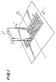
- FIGURE 1 shows a hand-held, one-dimensional scanning apparatus 7 scanning a non-distorted barcode 8 on a piece of paper.
- the scanning apparatus 7 will view the barcode 8 as having a shear distortion if axis 9 of the scanning elements of the scanning apparatus 7 is not perpendicular to the major axis 10 of the barcode 8 being scanned.
- Non-uniform horizontal and vertical shear distortions are disastrous for all existing types of barcodes because the positions and relative spacing of the elements of these barcodes cannot be reliably determined. There are two exceptions however.
- the color transition barcode disclosed in the '993 patent is not affected by non-uniform shear distortions because the intersection angle between each adjoining colored bar changes but does not affect scanability.
- the transition code is resistant to small amounts of this type of non-uniform shear distortion but excessive amounts of this distortion type will render this barcode unscannable because the transition point of each cell column becomes impossible to determine.
- non-uniform horizontal and vertical shear distortions are most commonly caused by artifacts of the scanning process when the longitudinal axis 9 of the scanning elements of the hand-held barcode scanner 7 variably change in relationship to the major axis 10 of the barcode 8 being scanned. This can occur when the hand-held barcode scanner 7 is rotated around its longitudinal axis 11 as the barcode 8 is being scanned.
- Wave distortion can occur over the horizontal or vertical axis of a barcode and can be both uniform and non-uniform in type.
- Wave in the context of this disclosure, implies a disturbance or oscillation between two points across the barcode in the direction parallel to the major axis of distortion.
- the disturbance or oscillation can be any type, such as sinusoidal, triangle, square, or saw.
- One characteristic attribute of uniform wave distortion is that the wave type is the same magnitude and phase on each end of the barcode. Non-uniform horizontal and vertical wave distortions do not have the same magnitude and phase on each opposing end of the barcode.
- Wave distortions can occur during the printing process where the object being marked moves relative to the printing apparatus. Wave distortions can be caused by an artifact of the scanning system. Referring again to FIGURE I, ideally, the barcode scanner 7 should not move along axis 12 of barcode 8 and only travel along the major axis 10 of barcode 8. Uniform wave distortions will be created if the hand-held scanner 7 begins to oscillate along axis 12 as the barcode is being scanned along axis 10.
- Linear barcodes are very tolerant of uniform horizontal wave distortions. However, they are not very tolerant of uniform vertical wave distortions because a scanner may perceive improper bar and space widths if the barcode scanner is not scanning exactly parallel to the axis of the barcode being scanned.
- Two-dimensional barcodes are not tolerant of any type of wave distortion as attempting to compute an imaginary grid over the barcode symbology to decode it is time consuming, requires a substantial amount of computing power and may be impossible without the aid of any suitable indicia from the barcode symbology indicating how the barcode is wave distorted. Barcode finder patterns and clock tracks help but under any substantial wave distortion, these indicia are generally not sufficient.
- Transition codes are extremely tolerant of uniform horizontal wave distortion. However, transition indica becomes lost under the remaining types of wave distortions and, likewise, the transition barcode becomes increasingly difficult to decode under these types of distortions.
- the color transition code disclosed in the '993 patent would be resistant to any type of uniform or non-uniform wave distortion because no transition indicia is lost under any type of wave distortion.
- a propagation error in a barcode symbology occurs when an error in one element of the barcode propagates to the next or preceding element of the barcode. Therefore, one error becomes two or more errors. This phenomenon generally is caused by elements values of a barcode symbology being dependent on the value or structure of an adjacent element.
- the transition barcode is one example of a barcode symbology that is subject to propagation errors.
- Propagation errors can also occur in color barcodes.
- United States Patent No. 5,576,528 to Chew et al. describes a method for increasing information density of a barcode symbology by generating multiple constituent barcode symbols where each symbol is formed in a different color selected from a group of various primary colors. Each colored symbol is then overlaid on top of each other thus forming an aggregate barcode symbol of various colors. In areas where the differently colored bars overlap each other, colors distinct from those in the original group of colors are formed. Using a reverse process, each individual barcode can then be separated and individually processed.
- the only barcode symbology that exhibits extraordinary resistance to all types of damage and distortions and is not subject to propagation errors is the color transition barcode disclosed in the '993 patent.
- This barcode is limited in its data capacity, does not contain a space efficient data encoding method, and does not contain any means for error correction and detection.
- Distortion and damage resistance is very important in barcode symbologies when using hand-held printers and hand-held scanners because the human hand tends to be unsteady which can cause variations in the printing and scanning processes.
- a barcode having inherent distortion resistance is easier and quicker to scan with area and linear barcode scanning devices.
- Damage and distortion resistance is also important when low quality printing processes are used, such as industrial ink-jet marking machines. Providing high quality marking and scanning machines is expensive and unnecessary if the barcode symbology being used is highly distortion resistant and contains a substantial amount of error detection and correction means. Distortion resistance is also important for most types of scanning applications because artifacts of the scanning system can cause the barcode to appear distorted.
- US-A-4856820 is described a machine and human readable coding system for a coded label carrying at least two identical messages, the label having a first column having a series of optical data carriers forming a first readable code, and a second column having a readable bar code, with the messages of the first and second columns being readable in opposite directions.
- An object of the present invention to provide a color barcode symbology where the relative sizes of its elements is not critical, thereby rendering the barcode resistant to any type of distortion or combinations thereof discussed hereinabove.
- Another object of the present invention to provide a color transition barcode symbology that can be decoded using a simple decoding algorithm without determining the type and magnitude of its distortion.
- Yet another object of the present invention to provide a color transition barcode symbology that can be scanned by an area imager or a linear imager with and without positional feedback.
- a further object of the present invention to provide a color transition barcode symbology that does not require start and stop patterns.
- An even further object of the present invention to provide a color transition barcode symbology that incorporates a space efficient data encoding system.
- Another object of the present invention to provide a color transition barcode symbology that can be printed at very high and low densities.
- Yet another object of the present invention to provide a color transition barcode symbology that has double error correction capabilities.
- An even further object of the present invention to provide a color transition barcode symbology that does not exhibit propagation error phenomenon.
- the present invention is directed to a color transition barcode symbology that satisfies the need for a barcode symbology that is resistant to the effects of all types of damage and distortions discussed previously, coupled with a space-efficient data encoding structure and double error correction capability.
- a barcode in accordance with the invention is defined in clam 1. Methods of reading the barcode are defined in claims 19 and 30. A method of encoding data into a barcode is defined in claim 38. Preferred or optional features are defined in the appended sub-claims 2-18, 20-29,31-37.
- a color transition barcode symbology comprises a plurality of values that can be concatenated together according to a set of rules and definitions for encoding data. To represent each of these values, a plurality of mutually exclusive color sets is formed. A plurality of color cells is then created, each having a color chosen from any of the available colors contained in any of the color sets.
- each color cell group comprises a plurality of color cells chosen from the same color set.
- Each color cell group can then be referred to as have been formed from one of the available color sets.
- Each color cell in each color cell group is always bounded by a color cell of another color from the same color set creating a first form of transition indicia.
- Each data value that the barcode symbology can encode is correlated to two or more color cell groups formed from different sets. As the barcode symbology is formed, each color cell group is bounded by a color cell group formed from a different color set creating a second form of transition indicia. To form a completed symbology, each data value to be concatenated together for encoding information is selected from one of the two or more color cell groups chosen to represent that data value. The actual color set of the color cell group chosen to represent that value depends on the color sets of the cell groups that will be bounding it in the barcode symbology so that two color cell groups from the same color set are never contiguous. A finder pattern is then constructed around the cell groups used to encode the data.
- the combinations of cell elements forming color cell groups are strategically chosen to be able to unambiguously correct or minimize the number of possibilities the damaged color cell group could contain.
- the first process of attempting to correct each color cell group is performed before the second error correction process requiring check-digits is initiated.
- This process is, therefore, a form of double error correction which increases the error correction capability of this barcode symbology and further increases the barcode's resistance to damage and distortions by increasing the efficiency of the Reed-Soloman error correction algorithms.
- each color cell group represents a value directly, propagation phenomenon is not present.
- each of the check-digits are represented by a group of color cell groups that are exclusive from the group of color cell groups used to represent the encoded data. This eliminates the use of start and stop patterns in the barcode symbology because check-digits can be placed at the end of the barcode and data at the beginning of the barcode, thereby, inherently identifying the starting point and ending point of the barcode symbology.
- the barcode has a finder pattern of a unique pattern having two components: a solid horizontal line of contiguous black cells 13 on the top edge of the barcode, and two solid vertical lines 14 and 15 of contiguous black cells placed along the start side edge 16 of the barcode and along the stop side edge 17 of the barcode.
- This finder pattern is used to define physical size, orientation and symbol distortion. This finder pattern is also used to discriminate this barcode from other barcode symbologies.
- each cell group is formed from a plurality of cells where each cell has a specific position within the cell group.
- each cell group is one cell wide by eight cells long and may be referred to as a cell column.
- Each cell in each cell column can be referenced by a cell position number where the lowest number, 0, represents the bottom cell in a cell column and the highest number, 7, represents the top cell in a cell column. These cell positions are referenced by a variable k.
- Each cell in each cell column has a color associated with it and the color chosen is either from a first set of colors or from a second set of colors.
- the first set of colors are RED, GREEN and BLUE otherwise known as additive colors.
- the second set of colors are CYAN, MAGENTA and YELLOW otherwise known as subtractive colors.
- the additive colors and subtractive colors are referred to as opposite color sets in this disclosure.
- An example of a cell column may be found in FIGURE 2 where cell column 18 comprises of cells 19-26.
- the top cell 19 has a k value of 7 and the bottom cell 26 has a k value of 0.
- each cell column There are three specific rules associated with each cell column. First, the color of the cells used in each cell column must only be from the additive color set or the subtractive color set. Combining cells of colors from both sets in one cell column is prohibited. Second, two cells of the same color in a cell column may not be contiguous. Third, a cell having a k value of 0 in a cell column may not have the same color as a cell having a k value of 7 in the same cell column.
- each cell column In order to encode data into the barcode, each cell column must represent a data value. Likewise, unique combinations of cell colors in each cell column represent specific data values. Because working with color names is inconvenient, each color of the additive and subtractive color sets are correlated into numbers. Because cell columns can either be formed from the additive set of colors or the subtractive set of colors, a single number can represent a color from both sets of colors. The following table shows the correlation: VALUE ADDITIVE SUBTRACTIVE 0 RED CYAN 1 GREEN MAGENTA 2 BLUE YELLOW
- a cell column formed from either additive or subtractive sets of colors has the same cell column value.
- a value in the barcode can be represented two ways; by a cell column formed from cells having colors from the additive color set or by a cell column formed from cells having colors from the subtractive color set. Further reference to cell column values will now be made using the value associated with each cell, not the color of each cell.
- a cell column formed from cells having additive colors CELL POSITION (k VALUE) CELL COLOR CELL VALUE 0 RED 0 1 GREEN 1 2 BLUE 2 3 RED 0 4 BLUE 2 5 RED 0 6 GREEN 1 7 BLUE 2 has an equivalent cell column value as a cell column formed from cells having the following subtractive colors: CELL POSITION (k VALUE) CELL COLOR CELL VALUE 0 CYAN 0 1 MAGENTA 1 2 YELLOW 2 3 CYAN 0 4 YELLOW 2 5 CYAN 0 6 MAGENTA 1 7 YELLOW 2
- cell position 1 from the additive cell column is RED and has a corresponding value of 0
- cell position 1 from the subtractive cell column is CYAN which also has a corresponding value of 0.
- a first way is by the cell column's raw value. Every unique combination of cells in a cell column is represented by a cell column raw number.
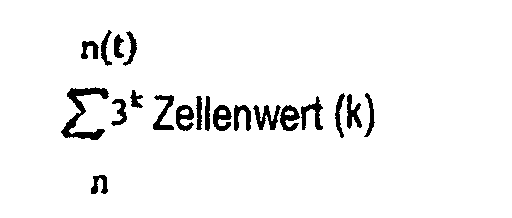
- the cell column raw number is computed by the following formula:
- both cell columns have equivalent cell column values because each cell in each respective cell column have equivalent values.
- Every raw value representing every possible combination of cell values in a cell column forms the global set. However, not every raw cell column value between 0 and 6561 would represent a valid cell column. This is because of the rules stated previously where two of the same cell colors (or cell values) cannot be contiguous and the color or value of the top cell cannot be the same color or value as the bottom cell. Under these constraints, a valid set of cell columns can be constructed, known hereinafter as the valid set.
- the valid set is comprised of two hundred and fifty-eight cell column combinations and is a subset of the global set.
- the valid set of cell columns formed from the global set is found in APPENDIX B where each valid cell column combination is tagged or identified by its raw cell column number.
- the barcode must be able to represent forty-seven different values which is the size of the Galois Field (GF) chosen in the preferred embodiment.
- the set size of cell columns or groups chosen is the same size as the barcode's Galois Field (GF) and the same cell groups used for data encodation are also used to encode the check-digits. This can cause ambiguity when decoding damaged barcodes because, under damage, it can be difficult to determine if the specific cell group represents a data value or check-digit value.
- the preferred embodiment uses ninety-four cell columns constructed from unique combinations of eight cell values.
- the first forty-seven cell columns represent data values and the second forty-seven cell groups represent Reed-Soloman check-digit values.
- Cell columns representing data values are described as data cell columns and cell columns representing Reed-Soloman check-digit values are described as Reed-Soloman cell columns.
- the actual value that each of the ninety-four cell columns represents has to be between 0 and 46 under a Galois Field of forty-seven but each cell column set is distinguishable from each other because they are now formed from unique combinations of cell values, thereby eliminating any ambiguity.
- miscellaneous cell columns are needed for the barcode of the present invention as well.
- the miscellaneous cell column set provides information about the structure of the barcode.
- the preferred embodiment uses twelve miscellaneous cell columns.
- the barcode requires a total of one hundred and six unique cell column combinations.
- each of the one hundred and six cell column combinations used in the barcode can either be represented with an additive set of colors or a subtractive set of colors.
- the one hundred and six cell column combinations used to encode the data value set, the Reed-Soloman value set, and the miscellaneous set are a subset of the two hundred and fifty-eight cell columns that comprise the valid set. These one hundred and six cell column combinations are referred to as the active set of cell columns and are shown in APPENDIX A.
- Each active cell column may be subjected to a number of different types of errors.
- a cell column comprised of eight cells may be subjected to a total of two hundred and fifty-five different types of cell column errors as shown in APPENDIX F where the "?" represents an unknown cell value and a "-" represents a known cell value.
- APPENDIX F APPENDIX F
- a set of valid solutions can be generated.
- Each possible solution must conform to the rules where two of the same cell colors, or cell values, cannot be contiguous and the color or value of the top cell cannot be the same color or value as the bottom cell of a cell column.
- each solution must be a member of the active set. A valid solution that conforms to this final requirement is called an active solution.
- the amount ofpossible solutions for each cell column error type diminishes.
- the number of valid solutions for each cell column error type is the same no matter what combination of cell columns are chosen for the active set.
- the number of active solutions is always less than the number of valid solutions, because the active set is smaller than and a subset of the valid set and depends on the combinations of cell columns used to construct the active set.
- Double data correcting ability involves attempting to correct errors in each cell column before the Reed-Soloman error correction algorithms are used to detect and correct errors.
- To create an effective double data correcting barcode one hundred and six cell columns are strategically chosen from the available cell columns contained in the valid set, thereby forming an active set of cell columns.
- the objective is to pick a group of one hundred and six cell columns from the valid set where the number of active solutions available for each cell column error type shown in APPENDIX F is minimized. This can best be demonstrated in reference to an active set of one hundred and six cell columns chosen as shown in APPENDIX A.
- a computer program can be written by one skilled in the art that takes a cell column from the active set in APPENDIX A and subjects each cell column to each cell column error type listed in APPENDIX F.
- One such computer program is found in APPENDIX G. The number of valid and active solutions is then calculated for each error type.
- APPENDIX H is a small portion of the output of such a computer program for the cell column having a raw value of eight hundred and seventy-five from the active set shown in APPENDIX A.
- APPENDIX F also compiles the number of active solutions for each cell column error type in each cell column of the active set being analyzed. A summary of this information for the active set of APPENDIX A is shown in APPENDIX I.
- column 27 represents the raw number of the cell column of the active set being analyzed;
- column 28 represents the cell values comprising each cell column referenced by k value,
- column 29 represents the percentage of cell column error types found in APPENDIX F subjected to each respective cell column that have only one active solution or, in other words, are unambiguously correctable;
- column 30 represents the percentage of cell column error types found in APPENDIX F subjected to each respective cell column that have two active solutions;
- column 31 represents the percentage of cell column error types found in APPENDIX F subjected to each respective cell column that have three active solutions.
- An average of one, two, and three active solution percentages is computed for all cell columns in the active set and is shown on line 32 of APPENDIX I.
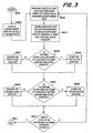
- the genetic algorithm used to find the best group of one hundred and six cell columns for the active set can be best understood when referencing FIGURE 3.
- the genetic algorithm starts out in step 3601 and progresses to step 3602 where, a population of ten active sets are retrieved. These ten active sets are known as parent sets.
- Step 3603 randomly selects two active sets from the ten active sets created in step 3602.
- Step 3604 then crossbreeds the two random selected active sets from 3603 forming a first active child set and a second active child set.
- Step 3605 determines if the first child set is more fit than both its respective parents. If so, that first child set is stored in step 3606. If the first child set is not more fit than both its respective parents, then it is discarded in step 3607.
- Step 3610 determines if the second child set is more fit than both its respective parents. If so, that second child set is stored in step 3608. If the second child set is not more fit than both its respective parents then it is discarded in step 3609. Step 3612 then determines if ten new children have been stored. If not, then step 3603 is re-executed to create in attempt to create more children that are more fit then their respective parents. If ten new children have been stored, then the algorithm terminates in step 3611.
- Two active sets 3701 and 3702 are chosen to be crossbred.
- Active set 3701 can also be referred to as active set A and active set 3702 can also be referred to as active set B.
- Active sets A and B are to be combined at crossover location 3705, thereby, forming two children 3703 and 3704.
- Crossover location 3705 is randomly changed to provide more variety in the offspring created every time the algorithm in FIGURE 3 is executed.
- Children 3703 and 3704 are also known as child sets AB and BA, respectively.
- Child set AB is formed by combining cell columns left of crossover point 3705 in active set A with cell columns right of crossover point 3705 in active set B.
- child set BA is formed by combining cell columns left of crossover point 3705 in active set B with cell columns right of crossover point 3705 in active set A.
- Determining whether a child set is more fit than its parents is dependent on two factors.
- the first factor is whether or not the child set comprises a valid set of cell columns.
- a cell column set is only valid if it contains cell columns found in the valid set of cell columns and if none of the cell columns in the child set are repeated more than once.
- the second factor is whether or not the child set has a higher score than both its parents.
- each set is assigned a score which is the average percentage of all unambiguously correctable cell column errors for each cell column in the set being analyzed. This score is generated by the computer program in APPENDIX F and shown in APPENDIX I at location 33. Therefore, a higher score indicates that, on average, each cell column comprising that active set is more correctable than an active set with a comparable lower score.
- the algorithm in FIGURE 3 is repeated as many times as desired until a suitable active set is found.
- the first time the algorithm is executed ten active sets of one hundred and six cell columns each are randomly created from the valid set of cell columns.
- the ten active parent sets loaded in step 3602 are the resultant child sets from the last execution of the algorithm. Therefore, each generation of ten active sets generated by the algorithm are always more fit or have higher scores than the previous generation.
- a mutation is periodically introduced in one or more of the ten active parent sets in an attempt to create more variability of the active parent population and, likewise, create more fit offspring.
- APPENDIX A An active set generated from multiple iterations of such a genetic algorithm is shown in APPENDIX A. It should be obvious that other active set combinations could be used that may have higher scores using these methods. At the time of the priority date, the most fit active set found by the inventors was the active set found in APPENDIX A.
- APPENDIX A shows the data cell column mapping
- APPENDIX D shows the Reed-Soloman cell column mapping
- APPENDIX E shows the miscellaneous cell column mapping.
- the barcode is formed by first determining which data values need to be concatenated together to encode the desired information according to the rules chosen to encode the desired information or data. Next, Reed-Soloman check-digits are computed. Finally, various miscellaneous values are determined that describe the data error correction format and structure of the barcode. All of these values are correlated to respective cell columns values (i.e. data values to data cell columns; Reed-Soloman values to Reed-Soloman cell columns; and miscellaneous values to miscellaneous cell columns) using the tables found in APPENDICES C, D and E. The cell columns values are then concatenated together in a sequence using specific rules of the symbology.
- the first cell column in the sequence is a miscellaneous cell column describing the starting mode of the barcode.
- Data cell columns are then added to the sequence.
- Reed-Soloman cell columns follow the data cell columns.
- the final cell column in the sequence is another miscellaneous cell column describing parameters for the Reed-Soloman error correction check-digits.
- cell columns are placed within the finder pattern starting from the left inner side 34 of the barcode finder pattern. It is required that when each cell column is placed in the barcode, that the cell columns alternate between the additive and subtractive color sets so that each cell column is always surrounded by a cell column of the opposite color set (i.e. additive cell columns are surrounded by subtractive cell columns etc.).
- the exception is the first and last cell columns where the left and right sides respectively are bounded by black finder pattern cells.
- the first cell column placed in location 35 is chosen from the additive set of colors.
- the second cell column placed in location 36 must be formed from the subtractive colors and the third cell column placed in location 37 must be formed from the additive colors, etc.
- the last cell column placed at location 38 within the finder pattern must always be from the subtractive set of colors.
- a completed barcode symbology has now been formed having resistance to the single or combined effects of: scaling distortions, perspective distortions, shear distortions, and wave distortions of both the uniform and non-uniform type traversing the barcode's vertical or horizontal axis. This can best be demonstrated by discussing methods of decoding this barcode symbology.
- the finder pattern is first located in the field of view of the barcode scanning apparatus.
- This process requires a two-dimensional barcode scanner or a linear barcode scanner that is capable of storing two-dimensional bitmap image for decoding.
- it is required to find the top cell of the first cell column for decoding. This can be done by locating both the solid vertical line of the finder pattern 15 on side 16 of the barcode, and the top horizontal bar 13 of the finder pattern. The intersection point of both these finder pattern components surrounds the top left corner of the top cell of the first cell column 38.
- top left corner has been identified, it is a simple matter to first scan towards the right and towards the bottom of the barcode until the top right, bottom right, and bottom left corners are located which yields the general size and shape of the top cell. The center point of the top cell is approximated using this information.
- the center of the top cell of the first cell column 38 is used as the starting point for the cell decoding algorithm shown in FIGURE 5.
- the starting point for decoding all cell columns using the algorithm in FIGURE 5 is always the center point of the top cell of the specific cell column being decoded.
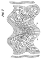
- FIGURE 5 depicts a moderately distorted barcode symbology of the type disclosed in this instant invention.
- the objective of the decoding algorithm in FIGURE 5 is to scan along each cell column until all eight cells in the cell column have been traversed and decoded.
- Line 39 depicts a path that the scanning algorithm of FIGURE 5 could incur.
- Step 3802 is next executed where initial data values and parameters are initialized.
- the variable i is a cell counter and represents the amount of cells traversed in the current cell column.
- the variable j represents the amount of cell columns that have been decoded and the current value of j always represents the current cell column being subjected to the decoding algorithm.
- Step 3802 initializes the scan angle to 180 degrees. Scan angles are always measured in degrees where a scan angle of 0 degrees or 360 degrees indicates a scan direction towards the top of the barcode.
- Step 3803 is executed next where the current scan position is placed in the center of the bottom cell of the current cell column being decoded using the procedure described previously. The color of that cell is determined and stored in step 3804.
- Step 3805 then advances the scan position towards the next cell immediately above the current cell using the current scan angle.
- Step 3806 looks for a color transition, if there is no color transition, then the scan continues in step 3805 using the current scan angle along the same path.
- step 3807 is executed which determines if the color of the newly penetrated cell is derived from the same color set as the recently exited cell. If this is not the case, then this is an indication that the newly penetrated cell is a member of an adjacent cell column or finder pattern.
- Step 3808 then relocates the scan position to the point immediately before the last color transition point and the new scan angle is chosen in step 3809. The new scan angle chosen should be chosen to avoid scanning in the reverse direction.
- step 3810 is executed storing the color of the newly penetrated cell.
- step 3811 increments i to keep track of how many cells have been traversed in the current cell column.
- step 3812 determines if all eight cells in the cell column have been decoded. If not, then step 3805 is reentered to continue scanning for additional cells. If all eight cells have been traversed, then step 3813 is executed which resets the cell counter i and increments the cell column counter j.
- Step 3814 checks to see if all of the cell columns have been scanned. If no, then step 3803 is reentered which initiates a new scan at the top cell of the next cell column. If step 3814 determines that all of the cell columns have been scanned, then the decoding algorithm terminates in step 3815.
- the scanning algorithm may not be capable of crossing the entire length of each cell column.
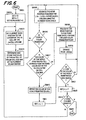
- the data captured using the scanning algorithm of FIGURE 5 is saved and the scanning algorithm shown in FIGURE 6 is then used to attempt to capture the remaining cells of the cell column being scanned.
- This scanning algorithm is similar to the scanning algorithm shown in FIGURE 5 except the scanning is initiated from the bottom cell of each cell column instead of the top cell.
- the second scanning algorithm in FIGURE 6 is only used if the first scanning algorithm shown in FIGURE 5 cannot be successfully completed. Because the second scanning algorithm needs to start at the bottom cell of the cell column to be scanned, that bottom cell needs to be located. This can be done by scanning along the bottom row of the barcode and counting transitions until the desired cell column is located.
- FIGURE 6 depicts a moderately distorted barcode symbology of the type disclosed in this instant invention.
- the objective of the decoding algorithm in FIGURE 6 is to scan along each cell column until all eight cells in the cell column have been traversed and decoded.
- Line 40 depicts the path on which the scanning algorithm of FIGURE 6 could incur.
- Step 3902 is next executed where initial data values and parameters are initialized.
- the variable i is a cell counter and represents the amount of cells traversed in the current cell column.
- the variable j represents the amount of cell columns that have been decoded and the current value of j always represents the current cell column being subjected to the decoding algorithm.
- i is set to seven so that the bottom cell of the cell column is scanned first and the scan-angle is set to 0 degrees so that the scanning direction generally proceeds towards the solid horizontal line of contiguous black cells 13.
- Step 3903 is executed next where the current scan position is placed in the center of the top cell of the current cell column being decoded using the procedure described previously.
- Step 3905 then advances the scan position towards the next cell immediately below the current cell using the current scan angle along path 40.
- Step 3906 looks for a color transition, if there is no color transition, then the scan continues in step 3905 using the current scan angle along the same path.
- step 3907 is executed which determines if the color of the newly penetrated cell is derived from the same color set as the recently exited cell. If this is not the case, then this is an indication that the newly penetrated cell is a member of an adjacent cell column or finder pattern.
- Step 3908 then relocates the scan position to the point immediately before the last color transition point and the new scan angle is chosen in step 3909. The new scan angle chosen should be close to the previous scan angle to avoid scanning in the reverse direction.
- step 3910 is executed storing the color of the newly penetrated cell.
- step 3911 decrements i to keep track of how many cells have been crossed in the current cell column.
- step 3912 determines if all eight cells in the cell column have been decoded. If not, then step 3905 is reentered to continue scanning for additional cells. If all eight cells have been traversed, then step 3913 is executed which resets the cell counter i and increments the cell column counter j.
- Step 3914 checks to see if all of the cell columns have scanned. If no, then step 3903 is reentered which initiates a new scan at the bottom cell of the next cell column. If step 3914 determines that all of the cell columns have been scanned, then the decoding algorithm terminates in step 3915.
- the barcode can be decoded using the above two decoding algorithms and, likewise, is resistant to all types of distortions discussed in this disclosure for the following reasons: (1) Because the barcode is transition based, the length of each cell in each cell column is not critical. The decoding algorithm shown in FIGURE 5 will successfully decode a cell of any length in a cell column by remaining in steps 3805 and 3806 until a color transition is detected. Therefore, any distortions that cause each cell height to variably change will not render the barcode unscannable. (2) When the decoding algorithm scans down each cell column, each color transition within the same color set serves as a clock track or indication that a new cell has been entered.
- each cell is always surrounded by a cell of a different color, a plethora of inherent clock tracks are formed within the barcode. Under practically any type of distortion, the clock tracks serve as indicators on how the barcode is distorted throughout the entire width and height of the barcode. This is advantageous under non-uniform distortions where the distortion is not uniformly distributed throughout the barcode symbology.
- each cell column is surrounded by a cell column formed from cells of the opposite color system, each cell column is bounded by a form of indicia that indicates that the decoding algorithm has traversed an adjoining cell column. Because of this indicia, the decoding algorithm shown in FIGURE 5 or FIGURE 6 is able to accurately track along each cell column under extreme amounts of uniform and non-uniform wave, shear, scaling and perspective distortions.
- the next step in the decoding process involves decoding the colors of the cells of each cell column into their respective data, Reed-Soloman, and miscellaneous values.
- the corresponding value of the color of each cell is stored in an eight element array.
- the array is then converted into a raw value using the following formula: where k is the position within the array and CellValue(k) represents the value of a cell placed in array position k.
- the raw value is then correlated, through a look-up table, to a data value, a Reed-Soloman value, or a miscellaneous value.
- Cell position 0 can only take three possible values: 0, 1 or 2. Substituting each of these three possible values into the unknown cell position 0 yields the following three cell column possibilities.
- the first possibility having a cell column raw value of 873 is an invalid cell column combination because contiguous cell positions 0 and 1 both contain a cell value of 0.
- the second possibility having a cell column raw value of 874 is a valid cell column but it is not part of the active set found in APPENDIX A, therefore, it is not an active solution.
- the third possibility having a cell column raw value of 875 is a member of the active set in APPENDIX A and is the only possible active solution. In this case, the damaged cell column can be immediately corrected. Because the active set in APPENDIX A has been optimally chosen using genetic algorithms, the number of active possibilities, in the case of damage, for all cell columns in the active set has been minimized.
- the cell column can be treated as an erasure and corrected using Reed-Soloman error correction algorithms. After each cell column has been successfully decoded, the desired information encoded in the barcode is extracted using the symbology's data encodation rules.
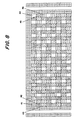
- a cell value of 0, 1 and 2 is always present at cells 41, 42 and 43, respectively, at the beginning of the symbology and at cells 44, 45 and 46 at the end of the symbology, see FIGURE 8. Because the first cell column at the beginning of the symbology is composed of cells from the additive set, cell 44 is always BLUE, cell 45 is always GREEN, and cell 46 is always RED. Likewise, because the last cell column at the end of the symbology is composed of cells from the subtractive set, cell 47 is always YELLOW, cell 48 is always MAGENTA, and cell 49 is always CYAN. Because cells 41, 42, 43, 44, 45, and 46 are all abeam the barcode's finder pattern, they are all easily found by the decoding algorithm before decoding of each cell column commences.
Landscapes
- Physics & Mathematics (AREA)
- Engineering & Computer Science (AREA)
- General Physics & Mathematics (AREA)
- Theoretical Computer Science (AREA)
- General Health & Medical Sciences (AREA)
- Electromagnetism (AREA)
- Health & Medical Sciences (AREA)
- Toxicology (AREA)
- Artificial Intelligence (AREA)
- Computer Vision & Pattern Recognition (AREA)
- Printers Characterized By Their Purpose (AREA)
- Inks, Pencil-Leads, Or Crayons (AREA)
- Numerical Control (AREA)
- Paints Or Removers (AREA)
Claims (38)
- Strichcode zum Darstellen codierter Daten, der mit einem Strichcodelesegerät (7) gelesen werden kann, wobei der Strichcode Folgendes umfasst:wobei jeder Zelle (19-26) in jeder der Spalten (18) eine Farbe zugeordnet ist, wobei die Farbe entweder einer ersten Farben-Gruppe oder einer zweiten Farben-Gruppe entstammt, wobei jeder Farbe in jeder Farben-gruppe ein Wert zugeordnet ist,mehrere Spalten (18), wobei jede Spalte (18) aus mehreren Zellen (19-26) gebildet ist und wobei jede Spalte (18) einen Rohwert darstellt,
wobei in jeder Spalte (18) die Zellen (19-26) entweder der ersten Farben-Gruppe oder der zweiten Farben-Gruppe entnommen sind,
wobei benachbarte Spalten (18) nicht aus der gleichen Farben-Gruppe gebildet sind, und
wobei aneinandergrenzende Zellen (19-26) in jeder Spalte (18) nicht aus der gleichen Farbe innerhalb der Farben-Gruppe bestehen. - Strichcode nach Anspruch 1, wobei ein Rohwert jeder Spalte (18) errechnet wird durch:wobei n = die erste Position der Zellen (19-26) in der Spalte (18), n(t) = die Gesamtzahl der Zellen (19-26) in der Spalte (18), k = die Position der Zelle (19-26) in der Spalte (18), und Zellenwert(k) = der Wert einer Zelle (19-26), die in der Position k angeordnet ist.
- Strichcode nach Anspruch 2, wobei der Rohwert von jeder Spalte (18) mit einem Datenwert, einem Reed-Solomon-Wert oder einem sonstigen Wert korreliert ist,
wobei der Datenwert, Reed-Solomon-Wert oder sonstige Wert die Daten darstellt, die in dem Strichcode codiert sind. - Strichcode nach Anspruch 1, wobei die erste Farben-Gruppe aus Rot, Grün und Blau besteht.
- Strichcode nach Anspruch 4, wobei die Farbe Rot einen Wert 0, die Farbe Grün einen Wert 1 und die Farbe Blau einen Wert 2 hat.
- Strichcode nach Anspruch 1, wobei es sich bei der ersten Farben-Gruppe um additive Farben handelt.
- Strichcode nach Anspruch 1, wobei die zweite Farben-Gruppe aus Cyan, Magenta und Gelb besteht.
- Strichcode nach Anspruch 7, wobei die Farbe Cyan einen Wert 0, die Farbe Magenta einen Wert 1 und die Farbe Gelb einen Wert 2 hat.
- Strichcode nach Anspruch 1, wobei es sich bei der zweiten Farben-Gruppe um subtraktive Farben handelt.
- Strichcode nach Anspruch 1, wobei die erste Farben-Gruppe aus Rot, Grün und Blau und die zweite Farben-Gruppe aus Cyan, Magenta und Gelb besteht.
- Strichcode nach Anspruch 10, wobei die Farbe Rot einen Wert 0, die Farbe Grün einen Wert 1 und die Farbe Blau einen Wert 2 hat und die Farbe Cyan einen Wert 0, die Farbe Magenta einen Wert 1 und die Farbe Gelb einen Wert 2 hat.
- Strichcode nach Anspruch 1, wobei jede Spalte (18) eine Zelle breit mal acht Zellen lang ist.
- Strichcode nach Anspruch 1, wobei 94 Spalten vorhanden sind.
- Strichcode nach Anspruch 13, wobei die ersten 47 Spalten Datenwerte darstellen und die zweiten 47 Spalten Reed-Solomon-Prüfzahlwerte darstellen.
- Strichcode nach Anspruch 14, der des Weiteren 12 Spalten zur Darstellung von Informationen zur Struktur des Strichcodes enthält.
- Strichcode nach Anspruch 1, wobei die Spalten (18), die Daten darstellen, eine erste und eine letzte Spalte (35, 38) aufweisen und des weiteren Finderspalten (15) neben der ersten und der letzten Spalte (35, 38) enthalten.
- Strichcode nach Anspruch 16, wobei die Finderspalten (15) von schwarzer Farbe sind.
- Strichcode nach Anspruch 16, wobei die erste Spalte (35) in dem Strichcode aus der ersten oder der zweiten Gruppe von aktiven Farben gebildet ist und die letzte Spalte (38) in dem Strichcode aus der anderen der ersten oder zweiten Gruppe von aktiven Farben gebildet ist.
- Verfahren zum Lesen eines nach Anspruch 1 gebildeten Strichcodes, wobei jede Spalte (18) eine oberste Zelle (19) und eine unterste Zelle (26) aufweist, wobei das Verfahren folgende Schritte umfasst:(a) Bereitstellen eines Strichcodelesegerätes (7);(b) Lokalisieren der obersten Zelle (19) der zu decodierenden Spalte (18) mit Hilfe des Strichcodelesegerätes (7);(c) Abtasten (3805), ausgehend von der obersten Zelle (19), bis zum unteren Ende der zu decodierenden Spalte (18), bis alle Zellen (19-26) in der zu decodierenden Spalte (18) abgetastet wurden;(d) Speichern (3810) der Farbe jeder Zelle (19-26) in der zu decodierenden Spalte (18) in einer Gruppierung;(e) Wiederholen der Schritte (b) bis (d) für jede zu decodierende Spalte (18), bis jede Spalte (18) decodiert wurde;(f) Konvertieren jeder Gruppierung zu einem Rohwert; und(g) Korrelieren des Rohwertes mit einem Datenwert, einem Reed-Solomon-Wert oder einem sonstigen Wert, wobei der Datenwert, Reed-Solomon-Wert oder sonstige Wert die Daten darstellt, die in dem Strichcode codiert sind.
- Verfahren nach Anspruch 19, wobei der Strichcode eine erste und eine letzte Spalte (35, 38) aufweist, zwischen denen mehrere Spalten (36, 37) angeordnet sind, und wobei die Spalten (18) in der Reihenfolge von der ersten zur letzten decodiert werden.
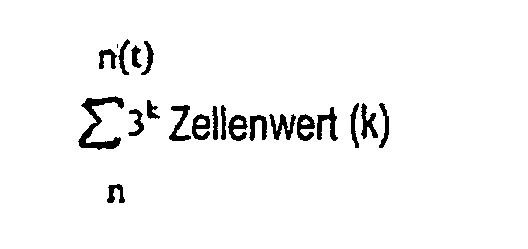
- Verfahren nach Anspruch 19, wobei sich in Schritt (f) die Gruppierung zu der Rohwertzahl verwandelt, und zwar unter Verwendung folgender Formel:wobei n = die erste Position der Zellen (19-26) in der Spalte (18), n(t) = die Gesamtzahl der Zellen (19-26) in der Spalte (18), k = die Position der Zelle (19-26) in der Spalte (18), und Zellenwert(k) = der Wert einer Zelle (19-26), die in der Position k angeordnet ist.
- Verfahren nach Anspruch 19, wobei Schritt (c) in der Weise ausgeführt wird, dass:(c1) die Farbe der obersten Zelle (19) festgestellt wird;(c2) unter Verwendung eines zuvor festgelegten Abtastwinkels von der obersten Zelle (19) ausgehend abwärts zur nächstgelegenen Zelle abgetastet wird, bis die der obersten Zelle (19) nächstgelegene Zelle abgetastet ist;(c3) die Farbe der als nächstes abgetasteten Zelle festgestellt wird;(c4) festgestellt wird, ob die Farbe der als nächstes abgetasteten Zelle sich in derselben Farben-Gruppe befindet wie die oberste Zelle (19);(c5) wobei, wenn sich die Farbe der als nächstes abgetasteten Zelle nicht in derselben Farben-Gruppe befindet wie die oberste Zelle (19), der Abtastwinkel geändert wird und eine andere Zelle abgetastet wird, die der obersten Zelle (19) am nächsten liegt, und festgestellt wird, ob sich die Farbe dieser zuletzt abgetasteten Zelle in derselben Farben-Gruppe befindet wie die oberste Zelle (19);(c6) wobei, wenn sich die Farbe der als nächstes abgetasteten Zelle in derselben Farben-Gruppe befindet wie die oberste Zelle (19), die zuletzt abgetastete Zelle in der Spalte (18) ist, und anschließend von dort mittels des zuvor festgelegten Abtastwinkels abwärts zu der von dort nächstgelegenen Zelle abgetastet wird;(c7) die Farbe der zuletzt abgetasteten Zelle abgetastet und festgestellt wird;(c8) festgestellt wird, ob die Farbe der zuletzt abgetasteten Zelle sich in derselben Farben-Gruppe befindet wie die zuvor abgetastete Zelle;(c9) wobei, wenn sich die Farbe der zuletzt abgetasteten Zelle nicht in derselben Farben-Gruppe befindet wie die zuvor abgetastete Zelle, der Abtastwinkel geändert wird und eine andere Zelle abgetastet wird, die der zuvor abgetasteten Zelle am nächsten liegt, und festgestellt wird, ob sich die Farbe dieser zuletzt abgetasteten Zelle in derselben Farben-Gruppe befindet wie die zuvor abgetastete Zelle;(c10) wobei, wenn sich die Farbe der zuletzt abgetasteten Zelle in derselben Farben-Gruppe befindet wie die zuvor abgetastete Zelle, die zuletzt abgetastete Zelle die nächste Zelle in der Spalte (18) ist, und anschließend die Schritte (c6)-(c9) wiederholt werden, bis das Ende der abgetasteten Spalte (18) erreicht ist.
- Verfahren nach Anspruch 19, wobei der Strichcode des Weiteren ein vertikales Findermuster (15) neben der ersten Spalte (35) und ein horizontales Findermuster (13) oberhalb der obersten Zelle (19) jeder Spalte (18) enthält, und wobei die oberste Zelle (19) der ersten Spalte (35) mittels des Strichcodelesegerätes (7) lokalisiert wird, um das vertikale Findermuster (15) und das horizontale Findermuster (13) zu lokalisieren, und wobei der Strichcode abgetastet wird, um die obere rechte, die untere rechte und die untere linke Ecke des Strichcodes zu finden, um die Größe des Strichcodes zu ermitteln, wobei sich der Position der obersten Zelle (19) der ersten Spalte (35) unter Verwendung der Größe des Strichcodes genähert wird.
- Verfahren nach Anspruch 23, wobei sich einem Mittelpunkt der obersten Zelle (19) der ersten Spalte (35) unter Verwendung der genäherten Größe und Form der obersten Zelle (19) der ersten Spalte (35) genähert wird.
- Verfahren nach Anspruch 19, wobei, wenn der Strichcode beschädigt ist und die Schritte (a) bis (g) nicht die gesamte Länge einer der Spalten (18) decodieren können, die mittels der Schritte (a) bis (g) erhaltenen Werte in der Gruppierung gespeichert werden und die folgenden Schritte ausgeführt werden, um jede Spalte (18) zu decodieren, die nicht durch die Schritte (a) bis (g) decodiert wurde:(h) Lokalisieren der untersten Zelle (26) der nicht decodierten Spalte (18) mittels des Strichcodelesegerätes (7);(i) Abtasten in Richtung des oberen Endes der nicht decodierten Spalte (18), bis alle Zellen (19-26) in der nicht decodierten Spalte (18) abgetastet und decodiert wurden;(j) Speichern der Farbe jeder Zelle (19-26) in der nicht decodierten Spalte (18) in der Gruppierung; und(k) Konvertieren der Gruppierung zu einer Zahl, welche die Daten darstellt, die in dem Strichcode codiert sind.
- Verfahren nach Anspruch 25, wobei Schritt (i) in der Weise ausgeführt wird, dass:(i1) die Farbe der untersten Zelle (26) festgestellt wird;(i2) unter Verwendung eines zuvor festgelegten Abtastwinkels von der untersten Zelle (26) ausgehend aufwärts zur nächstgelegenen Zelle abgetastet wird, bis die der untersten Zelle (26) nächstgelegene Zelle abgetastet ist;(i3) die Farbe der als nächstes abgetasteten Zelle festgestellt wird;(i4) festgestellt wird, ob die Farbe der als nächstes abgetasteten Zelle sich in derselben Farben-Gruppe befindet wie die unterste Zelle (26);(i5) wobei, wenn sich die Farbe der als nächstes abgetasteten Zelle nicht in derselben Farben-Gruppe befindet wie die unterste Zelle (26), der Abtastwinkel geändert wird und eine andere Zelle abgetastet wird, die der untersten Zelle (26) am nächsten liegt, und festgestellt wird, ob sich die Farbe dieser zuletzt abgetasteten Zelle in derselben Farben-Gruppe befindet wie die unterste Zelle (26);(i6) wobei, wenn sich die Farbe der als nächstes abgetasteten Zelle in derselben Farben-Gruppe befindet wie die unterste Zelle (26), die als nächstes abgetastete Zelle in der abgetasteten Spalte (18) ist, und anschließend von dort mittels des zuvor festgelegten Abtastwinkels aufwärts zu der von dort nächstgelegenen Zelle abgetastet wird;(i7) die Farbe der zuletzt abgetasteten Zelle abgetastet und festgestellt wird;(i8) festgestellt wird, ob die Farbe der zuletzt abgetasteten Zelle sich in derselben Farben-Gruppe befindet wie die zuvor abgetastete Zelle;(i9) wobei, wenn sich die Farbe der zuletzt abgetasteten Zelle nicht in derselben Farben-Gruppe befindet wie die zuvor abgetastete Zelle, der Abtastwinkel geändert wird und eine andere Zelle abgetastet wird, die der zuvor abgetasteten Zelle am nächsten liegt, und festgestellt wird, ob sich die Farbe dieser zuletzt abgetasteten Zelle in derselben Farben-Gruppe befindet wie die zuvor abgetastete Zelle;(i10) wobei, wenn sich die Farbe der zuletzt abgetasteten Zelle in derselben Farben-Gruppe befindet wie die zuvor abgetastete Zelle, die zuletzt abgetastete Zelle die nächste Zelle in der Spalte (18) ist, und anschließend die Schritte (i7)-(i9) wiederholt werden, bis das Ende der abgetasteten Spalte (18) erreicht ist.
- Strichcode nach Anspruch 1, wobei jede Spalte (18) eine oberste und eine unterste Zelle (19, 26) aufweist, wobei die oberste und die unterste Zelle (19, 26) von unterschiedlicher Farbe innerhalb der Farben-Gruppe, aus denen die Zellen (19-26) in der Spalte (18) bestehen, sind.
- Strichcode nach Anspruch 27, wobei ein Rohwert jeder Spalte (18) errechnet wird durch:wobei n = die erste Position der Zellen (19-26) in der Spalte (18), n(t) = die Gesamtzahl der Zellen (19-26) in der Spalte (18), k = die Position der Zelle (19-26) in der Spalte (18), und Zellenwert(k) = der Wert einer Zelle (19-26), die in der Position k angeordnet ist.

- Strichcode nach Anspruch 28, wobei der Rohwert von jeder Spalte (18) mit einem Datenwert, einem Reed-Solomon-Wert oder einem sonstigen Wert korreliert ist, wobei der Datenwert, Reed-Solomon-Wert oder sonstige Wert die Daten darstellt, die in dem Strichcode codiert sind.
- Verfahren zum Lesen eines nach Anspruch 27 gebildeten Strichcodes, wobei das Verfahren folgende Schritte umfasst:(a) Bereitstellen eines Strichcodelesegerätes (7);(b) Lokalisieren der obersten Zelle (19) der zu decodierenden Spalte (18) mit Hilfe des Strichcodelesegerätes (7);(c) Abtasten (3805), ausgehend von der obersten Zelle (19), bis zum unteren Ende der zu decodierenden Spalte (18), bis alle Zellen (19-26) in der zu decodierenden Spalte (18) abgetastet wurden;(d) Speichern (3810) der Farbe jeder Zelle (19-26) in der zu decodierenden Spalte (18) in einer Gruppierung;(e) Wiederholen der Schritte (b) bis (d) für jede zu decodierende Spalte (18), bis jede Spalte (18) decodiert wurde;(f) Konvertieren jeder Gruppierung zu einem Rohwert; und(g) Korrelieren des Rohwertes mit einem Datenwert, einem Reed-Solomon-Wert oder einem sonstigen Wert, wobei der Datenwert, Reed-Solomon-Wert oder sonstige Wert die Daten darstellt, die in dem Strichcode codiert sind.
- Verfahren nach Anspruch 30, wobei der Strichcode eine erste und eine letzte Spalte (35, 38) aufweist, zwischen denen mehrere Spalten (36, 37) angeordnet sind, und wobei die Spalten (18) in der Reihenfolge von der ersten zur letzten decodiert werden.
- Verfahren nach Anspruch 30, wobei sich in Schritt (f) die Gruppierung zu der Rohwertzahl verwandelt, und zwar unter Verwendung folgender Formel:wobei n = die erste Position der Zellen (19-26) in der Spalte (18), n(t) = die Gesamtzahl der Zellen (19-26) in der Spalte (18), k = die Position der Zelle (19-26) in der Spalte (18), und Zellenwert(k) = der Wert einer Zelle (19-26), die in der Position k angeordnet ist.

- Verfahren nach Anspruch 30, wobei Schritt (c) in der Weise ausgeführt wird, dass:(c1) die Farbe der obersten Zelle (19) festgestellt wird;(c2) unter Verwendung eines zuvor festgelegten Abtastwinkels von der obersten Zelle (19) ausgehend abwärts zur nächstgelegenen Zelle abgetastet wird, bis die der obersten Zelle (19) nächstgelegene Zelle abgetastet ist;(c3) die Farbe der als nächstes abgetasteten Zelle festgestellt wird;(c4) festgestellt wird, ob die Farbe der als nächstes abgetasteten Zelle sich in derselben Farben-Gruppe befindet wie die oberste Zelle (19);(c5) wobei, wenn sich die Farbe der als nächstes abgetasteten Zelle nicht in derselben Farben-Gruppe befindet wie die oberste Zelle (19), der Abtastwinkel geändert wird und eine andere Zelle abgetastet wird, die der obersten Zelle am nächsten liegt, und festgestellt wird, ob sich die Farbe dieser zuletzt abgetasteten Zelle in derselben Farben-Gruppe befindet wie die oberste Zelle (19);(c6) wobei, wenn sich die Farbe der als nächstes abgetasteten Zelle in derselben Farben-Gruppe befindet wie die oberste Zelle (19), die zuletzt abgetastete Zelle in der Spalte (18) ist, und anschließend von dort mittels des zuvor festgelegten Abtastwinkels abwärts zu der von dort nächstgelegenen Zelle abgetastet wird;(c7) die Farbe der zuletzt abgetasteten Zelle abgetastet und festgestellt wird;(c8) festgestellt wird, ob die Farbe der zuletzt abgetasteten Zelle sich in derselben Farben-Gruppe befindet wie die zuvor abgetastete Zelle;(c9) wobei, wenn sich die Farbe der zuletzt abgetasteten Zelle nicht in derselben Farben-Gruppe befindet wie die zuvor abgetastete Zelle, der Abtastwinkel geändert wird und eine andere Zelle abgetastet wird, die der zuvor abgetasteten Zelle am nächsten liegt, und festgestellt wird, ob sich die Farbe dieser zuletzt abgetasteten Zelle in derselben Farben-Gruppe befindet wie die zuvor abgetastete Zelle;(c10) wobei, wenn sich die Farbe der zuletzt abgetasteten Zelle in derselben Farben-Gruppe befindet wie die zuvor abgetastete Zelle, die zuletzt abgetastete Zelle die nächste Zelle in der Spalte (18) ist, und anschließend die Schritte (c6)-(c9) wiederholt werden, bis das Ende der abgetasteten Spalte (18) erreicht ist.
- Verfahren nach Anspruch 30, wobei der Strichcode des Weiteren ein vertikales Findermuster (15) neben der ersten Spalte (35) und ein horizontales Findermuster (13) oberhalb der obersten Zelle (19) jeder Spalte (18) enthält, und wobei die oberste Zelle (19) der ersten Spalte (35) mittels des Strichcodelesegerätes (7) lokalisiert wird, um das vertikale Findermuster (15) und das horizontale Findermuster (13) zu lokalisieren, und wobei der Strichcode abgetastet wird, um die obere rechte, die untere rechte und die untere linke Ecke des Strichcodes zu finden, um die Größe des Strichcodes zu ermitteln, wobei sich der Position der obersten Zelle (19) der ersten Spalte (35) unter Verwendung der Größe des Strichcodes genähert wird.
- Verfahren nach Anspruch 34, wobei sich einem Mittelpunkt der obersten Zelle (19) der ersten Spalte (35) unter Verwendung der genäherten Größe und Form der obersten Zelle (19) der ersten Spalte (35) genähert wird.
- Verfahren nach Anspruch 30, wobei, wenn der Strichcode beschädigt ist und die Schritte (a) bis (g) nicht die gesamte Länge einer der Spalten (18) decodieren können, die mittels der Schritte (a) bis (g) erhaltenen Werte in der Gruppierung gespeichert werden und die folgenden Schritte ausgeführt werden, um jede Spalte (18) zu decodieren, die nicht durch die Schritte (a) bis (g) decodiert wurde:(h) Lokalisieren der untersten Zelle (26) der nicht decodierten Spalte (18) mittels des Strichcodelesegerätes (7);(i) Abtasten in Richtung des oberen Endes der nicht decodierten Spalte (18), bis alle Zellen (19-26) in der nicht decodierten Spalte (18) abgetastet und decodiert wurden;(j) Speichern der Farbe jeder Zelle (19-26) in der nicht decodierten Spalte (18) in der Gruppierung; und(k) Konvertieren der Gruppierung zu einer Zahl, welche die Daten darstellt, die in dem Strichcode codiert sind.
- Verfahren nach Anspruch 36, wobei Schritt (i) in der Weise ausgeführt wird, dass:(i1) die Farbe der untersten Zelle (26) festgestellt wird;(i2) unter Verwendung eines zuvor festgelegten Abtastwinkels von der untersten Zelle (26) ausgehend aufwärts zur nächstgelegenen Zelle abgetastet wird, bis die der untersten Zelle (26) nächstgelegene Zelle abgetastet ist;(i3) die Farbe der als nächstes abgetasteten Zelle festgestellt wird;(i4) festgestellt wird, ob die Farbe der als nächstes abgetasteten Zelle sich in derselben Farben-Gruppe befindet wie die unterste Zelle (26);(i5) wobei, wenn sich die Farbe der als nächstes abgetasteten Zelle nicht in derselben Farben-Gruppe befindet wie die unterste Zelle (26), der Abtastwinkel geändert wird und eine andere Zelle abgetastet wird, die der untersten Zelle (26) am nächsten liegt, und festgestellt wird, ob sich die Farbe dieser zuletzt abgetasteten Zelle in derselben Farben-Gruppe befindet wie die unterste Zelle (26) ;(i6) wobei, wenn sich die Farbe der als nächstes abgetasteten Zelle in derselben Farben-Gruppe befindet wie die unterste Zelle (26), die als nächstes abgetastete Zelle in der abgetasteten Spalte (18) ist, und anschließend von dort mittels des zuvor festgelegten Abtastwinkels aufwärts zu der von dort nächstgelegenen Zelle abgetastet wird;(i7) die Farbe der zuletzt abgetasteten Zelle abgetastet und festgestellt wird;(i8) festgestellt wird, ob die Farbe der zuletzt abgetasteten Zelle sich in derselben Farben-Gruppe befindet wie die zuvor abgetastete Zelle;(i9) wobei, wenn sich die Farbe der zuletzt abgetasteten Zelle nicht in derselben Farben-Gruppe befindet wie die zuvor abgetastete Zelle, der Abtastwinkel geändert wird und eine andere Zelle abgetastet wird, die der zuvor abgetasteten Zelle am nächsten liegt, und festgestellt wird, ob sich die Farbe dieser zuletzt abgetasteten Zelle in derselben Farben-Gruppe befindet wie die zuvor abgetastete Zelle;(i10) wobei, wenn sich die Farbe der zuletzt abgetasteten Zelle in derselben Farben-Gruppe befindet wie die zuvor abgetastete Zelle, die zuletzt abgetastete Zelle die nächste Zelle in der Spalte (18) ist, und anschließend die Schritte (i7)-(i9) wiederholt werden, bis das Ende der abgetasteten Spalte (18) erreicht ist.
- Verfahren zum Codieren von Daten in einem Strichcode, der von einem Strichcodelesegerät (7) gelesen werden kann, wobei der Strichcode Folgendes umfasst: mehrere Spalten (18), wobei jede Spalte aus mehreren Zellen (19-26) gebildet ist und wobei jede Spalte einen Rohwert darstellt, wobei jeder Zelle in jeder der Spalten eine Farbe zugeordnet ist, wobei die Farbe entweder einer ersten Farben-Gruppe oder einer zweiten Farben-Gruppe entstammt, wobei jeder Farbe in jeder Farben-gruppe ein Wert zugeordnet ist, wobei in jeder Spalte die Zellen entweder der ersten Farben-Gruppe oder der zweiten Farben-Gruppe entnommen sind, wobei das Verfahren folgende Schritte umfasst:(a) Bilden einer validen Gruppe von Daten, die alle möglichen validen Kombinationen von Zellenwerten für eine Spalte des Strichcodes darstellt, wobei benachbarte Zellenwerte in jeder Kombination voneinander verschieden sind;(b) Auswählen zuvor festgelegter Kombinationen der validen Gruppe von Daten zur Darstellung von Daten, die in dem Strichcode codiert werden sollen;(c) Korrelieren der zuvor festgelegten Kombinationen mit den Farben, die durch die Zellenwerte in jeder Kombination dargestellt werden; und(d) Bilden von Spalten des Strichcodes auf der Basis der ausgewählten zuvor festgelegten Kombinationen, dergestalt, dass benachbarte Spalten nicht aus der gleichen Farben-Gruppe gebildet werden.
Applications Claiming Priority (3)
| Application Number | Priority Date | Filing Date | Title |
|---|---|---|---|
| US4344197P | 1997-04-08 | 1997-04-08 | |
| US43441P | 1997-04-08 | ||
| PCT/US1998/007243 WO1998045799A1 (en) | 1997-04-08 | 1998-04-08 | Distortion resistant double-data correcting color transition barcode and method of generating and using same |
Publications (3)
| Publication Number | Publication Date |
|---|---|
| EP1016027A1 EP1016027A1 (de) | 2000-07-05 |
| EP1016027A4 EP1016027A4 (de) | 2002-08-28 |
| EP1016027B1 true EP1016027B1 (de) | 2005-06-15 |
Family
ID=21927189
Family Applications (1)
| Application Number | Title | Priority Date | Filing Date |
|---|---|---|---|
| EP98914679A Expired - Lifetime EP1016027B1 (de) | 1997-04-08 | 1998-04-08 | Verformungsfeste, doppeldaten korrigierende, farbübergangsstreifenkode und ihres erzeugungs- und benutzungsverfahren |
Country Status (8)
| Country | Link |
|---|---|
| US (1) | US6070805A (de) |
| EP (1) | EP1016027B1 (de) |
| JP (1) | JP2001519068A (de) |
| AT (1) | ATE298113T1 (de) |
| CA (1) | CA2285626A1 (de) |
| DE (1) | DE69830597D1 (de) |
| IL (2) | IL131894A0 (de) |
| WO (1) | WO1998045799A1 (de) |
Families Citing this family (100)
| Publication number | Priority date | Publication date | Assignee | Title |
|---|---|---|---|---|
| US6155491A (en) * | 1998-05-29 | 2000-12-05 | Welch Allyn Data Collection, Inc. | Lottery game ticket processing apparatus |
| US6141441A (en) * | 1998-09-28 | 2000-10-31 | Xerox Corporation | Decoding data from patterned color modulated image regions in a color image |
| US6244764B1 (en) * | 2000-01-21 | 2001-06-12 | Robotic Vision Systems, Inc. | Method for data matrix print quality verification |
| KR100418862B1 (ko) * | 2000-03-14 | 2004-02-14 | 주식회사 칼라짚미디어 | 물리적으로 표현된 코드이미지를 이용한 광고 서비스 방법및 그 장치 |
| US7185816B1 (en) * | 2000-05-04 | 2007-03-06 | Symbol Technologies, Inc. | Bar code and method of forming a bar code having color for encoding supplemental information |
| US6941026B1 (en) * | 2000-06-13 | 2005-09-06 | Cognex Corporation | Method and apparatus using intensity gradients for visual identification of 2D matrix symbols |
| US6666377B1 (en) | 2000-07-18 | 2003-12-23 | Scott C. Harris | Bar code data entry device |
| US6691922B2 (en) * | 2000-12-28 | 2004-02-17 | Intermec Ip Corp. | Method and apparatus for encoding data in logos |
| US7111787B2 (en) | 2001-05-15 | 2006-09-26 | Hand Held Products, Inc. | Multimode image capturing and decoding optical reader |
| US6722569B2 (en) * | 2001-07-13 | 2004-04-20 | Welch Allyn Data Collection, Inc. | Optical reader having a color imager |
| US6834807B2 (en) | 2001-07-13 | 2004-12-28 | Hand Held Products, Inc. | Optical reader having a color imager |
| US20100194976A1 (en) * | 2001-10-10 | 2010-08-05 | Smith Peter H | Computer based aids for independent living and health |
| US20030080191A1 (en) * | 2001-10-26 | 2003-05-01 | Allen Lubow | Method and apparatus for applying bar code information to products during production |
| US20050131733A1 (en) * | 2001-12-17 | 2005-06-16 | Allen Lubow | Sealable individual bar coded packets |
| EP1466297A4 (de) * | 2001-12-17 | 2005-10-19 | Int Barcode Corp | Als einzelstrichcode wirkender doppelseitiger strichcode |
| US20030116630A1 (en) * | 2001-12-21 | 2003-06-26 | Kba-Giori S.A. | Encrypted biometric encoded security documents |
| US20030117262A1 (en) * | 2001-12-21 | 2003-06-26 | Kba-Giori S.A. | Encrypted biometric encoded security documents |
| US8041645B2 (en) * | 2003-08-21 | 2011-10-18 | Pitney Bowes Inc. | Document security utilizing color gradients |
| US7299984B2 (en) * | 2003-08-21 | 2007-11-27 | Pitney Bowes Inc. | Postage indicia including encoded ink characteristic data |
| US7055746B2 (en) * | 2004-04-07 | 2006-06-06 | Pitney Bowes Inc. | Postage indicia including color bar sequence to aid in authentication |
| WO2005067533A2 (en) * | 2004-01-14 | 2005-07-28 | International Barcode Corporation | Scannable virtual bar code image compensating for distortions |
| WO2005086076A1 (en) * | 2004-03-03 | 2005-09-15 | Signal Tree Research, Inc. | System for encoding information using colors |
| KR100560330B1 (ko) * | 2004-04-21 | 2006-03-30 | 에이디정보통신 주식회사 | 색상 보정이 가능한 대용량 2차원 칼라 바코드인코딩/디코딩 시스템 및 그 방법 |
| US7118041B2 (en) | 2004-04-27 | 2006-10-10 | Hewlett-Packard Development Company, L.P. | Two-dimensional color barcode with preserved plane and lossy plane layers |
| EP1593935A1 (de) * | 2004-05-06 | 2005-11-09 | Leica Geosystems AG | Höhenmesslatte, ihre Verwendung in einem Höhenmessgerät und in einem Verfahren zur Bestimmung von Höhen |
| WO2005111923A2 (en) * | 2004-05-06 | 2005-11-24 | United States Postal Service | Scannable article having a signature section with alignment bars |
| US7229025B2 (en) * | 2004-06-07 | 2007-06-12 | Pitney Bowes Inc. | Barcode with enhanced additional stored data |
| US7751585B2 (en) * | 2004-06-28 | 2010-07-06 | Microsoft Corporation | System and method for encoding high density geometric symbol set |
| US9296214B2 (en) * | 2004-07-02 | 2016-03-29 | Zih Corp. | Thermal print head usage monitor and method for using the monitor |
| US7710598B2 (en) * | 2004-08-23 | 2010-05-04 | Harrison Jr Shelton E | Polychromatic encoding system, method and device |
| US7454086B2 (en) | 2004-09-28 | 2008-11-18 | Ricoh Company, Ltd. | Techniques for positioning images in electronic documents |
| JP2006127025A (ja) * | 2004-10-27 | 2006-05-18 | Design Barcode Kk | デザインバーコード |
| DE102004057495A1 (de) * | 2004-11-29 | 2006-06-01 | Siemens Ag | Feld zur Darstellung farbcodierter Daten, Verfahren zur Codierung von Daten, Verfahren zur Eingabe von Daten |
| US20070021191A1 (en) * | 2005-02-15 | 2007-01-25 | White Michael L | Method and apparatus for storing information on a wager gaming voucher |
| US7676038B2 (en) * | 2005-03-08 | 2010-03-09 | Hewlett-Packard Development Company, L.P. | Secure printing method to thwart counterfeiting |
| US7455013B2 (en) * | 2005-03-08 | 2008-11-25 | Hewlett-Packard Development Company, L.P. | Secure printing method to thwart counterfeiting |
| US8599174B2 (en) * | 2005-03-18 | 2013-12-03 | The Invention Science Fund I, Llc | Verifying a written expression |
| US7809215B2 (en) * | 2006-10-11 | 2010-10-05 | The Invention Science Fund I, Llc | Contextual information encoded in a formed expression |
| US8102383B2 (en) * | 2005-03-18 | 2012-01-24 | The Invention Science Fund I, Llc | Performing an action with respect to a hand-formed expression |
| US7873243B2 (en) | 2005-03-18 | 2011-01-18 | The Invention Science Fund I, Llc | Decoding digital information included in a hand-formed expression |
| US8229252B2 (en) | 2005-03-18 | 2012-07-24 | The Invention Science Fund I, Llc | Electronic association of a user expression and a context of the expression |
| US7791593B2 (en) * | 2005-03-18 | 2010-09-07 | The Invention Science Fund I, Llc | Machine-differentiatable identifiers having a commonly accepted meaning |
| US8290313B2 (en) * | 2005-03-18 | 2012-10-16 | The Invention Science Fund I, Llc | Electronic acquisition of a hand formed expression and a context of the expression |
| US8340476B2 (en) | 2005-03-18 | 2012-12-25 | The Invention Science Fund I, Llc | Electronic acquisition of a hand formed expression and a context of the expression |
| US8787706B2 (en) | 2005-03-18 | 2014-07-22 | The Invention Science Fund I, Llc | Acquisition of a user expression and an environment of the expression |
| US8232979B2 (en) * | 2005-05-25 | 2012-07-31 | The Invention Science Fund I, Llc | Performing an action with respect to hand-formed expression |
| US9114187B2 (en) | 2005-04-28 | 2015-08-25 | Zih Corp. | Antimicrobial coating for identification devices |
| US20060293929A1 (en) * | 2005-06-23 | 2006-12-28 | Chunghwa Telecom Co., Ltd. | Electronic-ticket service system based on color-scale-code image recognition |
| EP1826705A1 (de) | 2006-02-25 | 2007-08-29 | F.Hoffmann-La Roche Ag | Analytisches Verbrauchsmittel und Anordnung zum Auslesen von Informationen |
| US8789756B2 (en) * | 2006-02-25 | 2014-07-29 | Roche Diagnostics Operations, Inc. | Test element coding apparatuses, systems and methods |
| US8550350B2 (en) * | 2006-02-28 | 2013-10-08 | Konica Minolta Laboratory U.S.A., Inc. | Color barcode with enhanced capacity and readability for a closed loop system |
| US7478746B2 (en) * | 2006-05-31 | 2009-01-20 | Konica Minolta Systems Laboratory, Inc. | Two-dimensional color barcode and method of generating and decoding the same |
| CN101467161A (zh) * | 2006-06-14 | 2009-06-24 | 威泰克公司 | 多维符号体系和相关方法 |
| US20090194596A1 (en) * | 2006-07-19 | 2009-08-06 | B-Core Inc. | Optical Symbol, Item to Which Optical Symbol is Attached, Method of Attaching Optical Symbol to Item, and Optical Recognition Code Recognizing Method |
| US8113432B2 (en) * | 2006-07-19 | 2012-02-14 | B-Core Inc. | Apparatus for recognizing an optical recognition code in which a code symbol of a 1-dimensional color bit code indicative of certain data is divided into a plurality of code symbols |
| FR2918825B1 (fr) * | 2007-07-09 | 2009-11-27 | Jacques Rivaillier | Procede codant sequentiellement sur plusieurs caracteres ou plusieurs octets une information fragmentee independamment de l'information pre-existante. |
| WO2009054363A1 (ja) * | 2007-10-25 | 2009-04-30 | Takahiro Saito | 情報コード |
| TW200937299A (en) * | 2007-11-09 | 2009-09-01 | B Core Inc | Optical identification code and marking method of the same and recognition method of the same and goods marked with the same, recognition method of colour and computer program executing the ridognition method of colour, auto identification code using col |
| EP2248068B1 (de) | 2008-01-29 | 2014-04-30 | Veritec, Inc. | Zweidimensionales symbol und verfahren, um es zu lesen |
| US9794448B1 (en) * | 2008-06-04 | 2017-10-17 | Hao-jan Chang | Visible multiple codes system, method and apparatus |
| US8194973B2 (en) | 2008-06-13 | 2012-06-05 | Hewlett-Packard Development Company, L.P. | Decoding information from a captured image |
| US8720780B2 (en) * | 2009-04-08 | 2014-05-13 | Blackberry Limited | Systems, devices, and methods for displaying a barcode at a computing device |
| US8047447B2 (en) * | 2009-05-06 | 2011-11-01 | Xerox Corporation | Method for encoding and decoding data in a color barcode pattern |
| US8879994B2 (en) | 2009-10-02 | 2014-11-04 | Blackberry Limited | Methods and devices for facilitating Bluetooth pairing using a camera as a barcode scanner |
| US8593697B2 (en) * | 2010-01-11 | 2013-11-26 | Hewlett-Packard Development Company, L.P. | Document processing |
| US9105023B2 (en) * | 2010-02-26 | 2015-08-11 | Blackberry Limited | Methods and devices for transmitting and receiving data used to activate a device to operate with a server |
| US9298964B2 (en) | 2010-03-31 | 2016-03-29 | Hand Held Products, Inc. | Imaging terminal, imaging sensor to determine document orientation based on bar code orientation and methods for operating the same |
| US9104934B2 (en) | 2010-03-31 | 2015-08-11 | Hand Held Products, Inc. | Document decoding system and method for improved decoding performance of indicia reading terminal |
| US9396421B2 (en) | 2010-08-14 | 2016-07-19 | Rujan Entwicklung Und Forschung Gmbh | Producing, capturing and using visual identification tags for moving objects |
| US8657200B2 (en) | 2011-06-20 | 2014-02-25 | Metrologic Instruments, Inc. | Indicia reading terminal with color frame processing |
| US9111186B2 (en) * | 2011-10-12 | 2015-08-18 | University Of Rochester | Color barcodes for mobile applications: a per channel framework |
| MX346785B (es) * | 2012-06-06 | 2017-03-30 | Sodyo Ltd | Anclajes para la navegación basado en la localización y aplicaciones de realidad aumentada. |
| US10147214B2 (en) | 2012-06-06 | 2018-12-04 | Sodyo Ltd. | Display synchronization using colored anchors |
| GB2526261B (en) | 2014-04-28 | 2017-08-02 | Gelliner Ltd | Encoded cells and cell arrays |
| US10635958B2 (en) | 2015-01-28 | 2020-04-28 | Sodyo Ltd. | Hybrid visual tagging using customized colored tiles |
| US10546172B2 (en) | 2015-03-30 | 2020-01-28 | Temptime Corporation | Two dimensional barcode with dynamic environmental data system, method, and apparatus |
| EP3278266B1 (de) | 2015-03-30 | 2023-09-13 | Temptime Corporation | Zweidimensionaler barcode mit dynamischem umweltdatensystem, verfahren und vorrichtung |
| EP3104306B2 (de) * | 2015-06-11 | 2023-11-01 | Scantrust SA | Zweidimensionaler strichcode |
| US10936837B1 (en) * | 2018-05-23 | 2021-03-02 | Amazon Technologies, Inc. | 2D barcode overlays |
| CN112424794B (zh) | 2018-07-11 | 2024-06-07 | 索迪欧有限公司 | 使用马赛克图像传感器检测高分辨率的机器可读标签 |
| US10534948B1 (en) | 2019-03-18 | 2020-01-14 | Capital One Services, Llc | Optimizing detection of images in relation to targets based on colorspace transformation techniques |
| US10496911B1 (en) | 2019-03-18 | 2019-12-03 | Capital One Services, Llc | Detection of images in relation to targets based on colorspace transformation techniques and utilizing ultraviolet and infrared light |
| US10509991B1 (en) | 2019-03-18 | 2019-12-17 | Capital One Services, Llc | Detection of images in relation to targets based on colorspace transformation techniques and utilizing infrared light |
| US10496862B1 (en) | 2019-03-18 | 2019-12-03 | Capital One Services, Llc | Detection of images in relation to targets based on colorspace transformation techniques and utilizing ultraviolet light |
| US10523420B1 (en) | 2019-04-18 | 2019-12-31 | Capital One Services, Llc | Transmitting encoded data along transmission mediums based on colorspace schemes |
| US10614635B1 (en) | 2019-07-25 | 2020-04-07 | Capital One Services, Llc | Augmented reality system with color-based fiducial marker |
| US11120241B2 (en) * | 2019-07-30 | 2021-09-14 | Temptime Corporation | Two dimensional barcode provided with dynamic environmental indicator provided within a gap |
| US10833852B1 (en) | 2019-10-03 | 2020-11-10 | Capital One Services, Llc | Encoded data along tape based on colorspace schemes |
| US10715183B1 (en) * | 2019-10-25 | 2020-07-14 | Capital One Services, Llc | Data encoding with error-correcting code pursuant to colorspace schemes |
| US10867226B1 (en) | 2019-11-04 | 2020-12-15 | Capital One Services, Llc | Programmable logic array and colorspace conversions |
| US10762371B1 (en) | 2019-11-14 | 2020-09-01 | Capital One Services, Llc | Object detection techniques using colorspace conversions |
| US10878600B1 (en) | 2019-12-10 | 2020-12-29 | Capital One Services, Llc | Augmented reality system with color-based fiducial marker utilizing local adaptive technology |
| JP7358284B2 (ja) * | 2020-03-25 | 2023-10-10 | 株式会社日立製作所 | コード、情報処理システム、及び情報処理装置 |
| US11302036B2 (en) | 2020-08-19 | 2022-04-12 | Capital One Services, Llc | Color conversion between color spaces using reduced dimension embeddings |
| US11615280B2 (en) | 2020-08-31 | 2023-03-28 | Temptime Corporation | Barcodes with security material and readers for same |
| US11951761B2 (en) | 2020-09-17 | 2024-04-09 | Temptime Corporation | Environmental history monitor with security features |
| US11241902B1 (en) | 2020-09-17 | 2022-02-08 | Temptime Corporation | Environmental history monitor with positional displacement and security features |
| US11734539B2 (en) | 2021-04-05 | 2023-08-22 | Temptime Corporation | Dynamic optical property windows in indicia with sensors |
| US12020097B1 (en) | 2023-01-31 | 2024-06-25 | Temptime Corporation | 2D bar code using active overlays |
| US20250252425A1 (en) * | 2024-02-06 | 2025-08-07 | Multi Packaging Solutions, Inc. | Secure transaction card |
Family Cites Families (9)
| Publication number | Priority date | Publication date | Assignee | Title |
|---|---|---|---|---|
| CH495017A (de) * | 1968-07-16 | 1970-08-15 | Ciba Geigy | Verfahren zur Abtastung von Farbcodes und zu deren Umwandlung in Binärcodes sowie Einrichtung zur Durchführung dieses Verfahrens |
| US4251798A (en) * | 1978-05-31 | 1981-02-17 | Symbol Technologies | Portable laser scanning arrangement for and method of evaluating and validating bar code symbols |
| US4283622A (en) * | 1979-05-14 | 1981-08-11 | Ncr Corporation | Bar code reader |
| US4783838A (en) * | 1984-12-26 | 1988-11-08 | Konishiroku Photo Industry Co., Ltd. | Image processing method and apparatus therefor |
| US4856820A (en) * | 1987-01-21 | 1989-08-15 | Wright Line Inc. | Coding system |
| US4924078A (en) * | 1987-11-25 | 1990-05-08 | Sant Anselmo Carl | Identification symbol, system and method |
| US4998010A (en) * | 1988-04-08 | 1991-03-05 | United Parcel Service Of America, Inc. | Polygonal information encoding article, process and system |
| US5153928A (en) * | 1989-06-09 | 1992-10-06 | Casio Computer Co., Ltd. | Method and apparatus for recording/reproducing mesh pattern data |
| CA2053460A1 (en) * | 1991-09-13 | 1993-03-14 | Eugene Bernard Joseph | Analog waveform decoder |
-
1998
- 1998-04-08 IL IL13189498A patent/IL131894A0/xx active IP Right Grant
- 1998-04-08 DE DE69830597T patent/DE69830597D1/de not_active Expired - Lifetime
- 1998-04-08 JP JP54315598A patent/JP2001519068A/ja not_active Ceased
- 1998-04-08 AT AT98914679T patent/ATE298113T1/de not_active IP Right Cessation
- 1998-04-08 WO PCT/US1998/007243 patent/WO1998045799A1/en not_active Ceased
- 1998-04-08 EP EP98914679A patent/EP1016027B1/de not_active Expired - Lifetime
- 1998-04-08 US US09/057,415 patent/US6070805A/en not_active Expired - Lifetime
- 1998-04-08 CA CA002285626A patent/CA2285626A1/en not_active Abandoned
-
1999
- 1999-09-14 IL IL131894A patent/IL131894A/en not_active IP Right Cessation
Also Published As
| Publication number | Publication date |
|---|---|
| ATE298113T1 (de) | 2005-07-15 |
| CA2285626A1 (en) | 1998-10-15 |
| EP1016027A4 (de) | 2002-08-28 |
| JP2001519068A (ja) | 2001-10-16 |
| US6070805A (en) | 2000-06-06 |
| DE69830597D1 (de) | 2005-07-21 |
| IL131894A (en) | 2006-06-11 |
| IL131894A0 (en) | 2001-03-19 |
| EP1016027A1 (de) | 2000-07-05 |
| WO1998045799A1 (en) | 1998-10-15 |
Similar Documents
| Publication | Publication Date | Title |
|---|---|---|
| US6070805A (en) | Distortion resistant double-data correcting color transition barcode and method of generating and using same | |
| US7281660B2 (en) | Two-dimensional code having superior decoding properties making it possible to control the level of error correcting codes, and method for encoding and decoding the same | |
| US6685095B2 (en) | Apparatus and method for decoding damaged optical codes | |
| US7028911B2 (en) | Methods and systems for encoding and decoding data in 2D symbology | |
| US7510125B2 (en) | Multi-dimensional symbologies and related methods | |
| US6321986B1 (en) | Robust machine-readable symbology and method and apparatus for printing and reading same | |
| US5959285A (en) | Two-dimensional bar code symbology using gray code encodation scheme | |
| US7185816B1 (en) | Bar code and method of forming a bar code having color for encoding supplemental information | |
| US4794239A (en) | Multitrack bar code and associated decoding method | |
| US4998010A (en) | Polygonal information encoding article, process and system | |
| US5553084A (en) | Error correction enhancement for code one and other machine-readable symbologies | |
| US20250053768A1 (en) | Two-dimensional barcode, method and system for encoding data into said two-dimensional barcode, and method and system for imaging and decoding said two-dimensional barcode | |
| KR20010006507A (ko) | 기계-판독 가능한 심볼로지 및 그의 인쇄 및 판독 방법 및 장치 | |
| US5811787A (en) | Two-dimensional bar code symbology using implicit version information encoding | |
| KR20030085511A (ko) | 2차원 바코드 카드 및 그 디코딩 방법 | |
| US6330972B1 (en) | Error correction enhancement for code 93i and other machine-readable symbologies | |
| US6761314B2 (en) | Bar code symbology for consumer scanning applications | |
| JPH04277887A (ja) | アドオンバーコード読取装置 | |
| MXPA99009196A (en) | Distortion resistant double-data correcting color transition barcode and method of generating and using same |
Legal Events
| Date | Code | Title | Description |
|---|---|---|---|
| PUAI | Public reference made under article 153(3) epc to a published international application that has entered the european phase |
Free format text: ORIGINAL CODE: 0009012 |
|
| 17P | Request for examination filed |
Effective date: 19990921 |
|
| AK | Designated contracting states |
Kind code of ref document: A1 Designated state(s): AT BE CH DE DK ES FI FR GB IT LI NL SE |
|
| RAP1 | Party data changed (applicant data changed or rights of an application transferred) |
Owner name: ZIH CORPORATION |
|
| A4 | Supplementary search report drawn up and despatched |
Effective date: 20020716 |
|
| AK | Designated contracting states |
Kind code of ref document: A4 Designated state(s): AT BE CH DE DK ES FI FR GB IT LI NL SE |
|
| RIC1 | Information provided on ipc code assigned before grant |
Free format text: 7G 06K 7/12 A, 7G 06K 19/06 B |
|
| 17Q | First examination report despatched |
Effective date: 20040611 |
|
| GRAP | Despatch of communication of intention to grant a patent |
Free format text: ORIGINAL CODE: EPIDOSNIGR1 |
|
| GRAS | Grant fee paid |
Free format text: ORIGINAL CODE: EPIDOSNIGR3 |
|
| GRAA | (expected) grant |
Free format text: ORIGINAL CODE: 0009210 |
|
| AK | Designated contracting states |
Kind code of ref document: B1 Designated state(s): AT BE CH DE DK ES FI FR GB IT LI NL SE |
|
| PG25 | Lapsed in a contracting state [announced via postgrant information from national office to epo] |
Ref country code: NL Free format text: LAPSE BECAUSE OF FAILURE TO SUBMIT A TRANSLATION OF THE DESCRIPTION OR TO PAY THE FEE WITHIN THE PRESCRIBED TIME-LIMIT Effective date: 20050615 Ref country code: LI Free format text: LAPSE BECAUSE OF FAILURE TO SUBMIT A TRANSLATION OF THE DESCRIPTION OR TO PAY THE FEE WITHIN THE PRESCRIBED TIME-LIMIT Effective date: 20050615 Ref country code: IT Free format text: LAPSE BECAUSE OF FAILURE TO SUBMIT A TRANSLATION OF THE DESCRIPTION OR TO PAY THE FEE WITHIN THE PRESCRIBED TIME-LIMIT;WARNING: LAPSES OF ITALIAN PATENTS WITH EFFECTIVE DATE BEFORE 2007 MAY HAVE OCCURRED AT ANY TIME BEFORE 2007. THE CORRECT EFFECTIVE DATE MAY BE DIFFERENT FROM THE ONE RECORDED. Effective date: 20050615 Ref country code: FI Free format text: LAPSE BECAUSE OF FAILURE TO SUBMIT A TRANSLATION OF THE DESCRIPTION OR TO PAY THE FEE WITHIN THE PRESCRIBED TIME-LIMIT Effective date: 20050615 Ref country code: CH Free format text: LAPSE BECAUSE OF FAILURE TO SUBMIT A TRANSLATION OF THE DESCRIPTION OR TO PAY THE FEE WITHIN THE PRESCRIBED TIME-LIMIT Effective date: 20050615 Ref country code: BE Free format text: LAPSE BECAUSE OF FAILURE TO SUBMIT A TRANSLATION OF THE DESCRIPTION OR TO PAY THE FEE WITHIN THE PRESCRIBED TIME-LIMIT Effective date: 20050615 Ref country code: AT Free format text: LAPSE BECAUSE OF FAILURE TO SUBMIT A TRANSLATION OF THE DESCRIPTION OR TO PAY THE FEE WITHIN THE PRESCRIBED TIME-LIMIT Effective date: 20050615 |
|
| REG | Reference to a national code |
Ref country code: GB Ref legal event code: FG4D Ref country code: CH Ref legal event code: EP |
|
| REF | Corresponds to: |
Ref document number: 69830597 Country of ref document: DE Date of ref document: 20050721 Kind code of ref document: P |
|
| PG25 | Lapsed in a contracting state [announced via postgrant information from national office to epo] |
Ref country code: SE Free format text: LAPSE BECAUSE OF FAILURE TO SUBMIT A TRANSLATION OF THE DESCRIPTION OR TO PAY THE FEE WITHIN THE PRESCRIBED TIME-LIMIT Effective date: 20050915 Ref country code: DK Free format text: LAPSE BECAUSE OF FAILURE TO SUBMIT A TRANSLATION OF THE DESCRIPTION OR TO PAY THE FEE WITHIN THE PRESCRIBED TIME-LIMIT Effective date: 20050915 |
|
| PG25 | Lapsed in a contracting state [announced via postgrant information from national office to epo] |
Ref country code: DE Free format text: LAPSE BECAUSE OF FAILURE TO SUBMIT A TRANSLATION OF THE DESCRIPTION OR TO PAY THE FEE WITHIN THE PRESCRIBED TIME-LIMIT Effective date: 20050916 |
|
| NLV1 | Nl: lapsed or annulled due to failure to fulfill the requirements of art. 29p and 29m of the patents act | ||
| REG | Reference to a national code |
Ref country code: CH Ref legal event code: PL |
|
| PG25 | Lapsed in a contracting state [announced via postgrant information from national office to epo] |
Ref country code: GB Free format text: LAPSE BECAUSE OF NON-PAYMENT OF DUE FEES Effective date: 20060408 |
|
| PLBE | No opposition filed within time limit |
Free format text: ORIGINAL CODE: 0009261 |
|
| STAA | Information on the status of an ep patent application or granted ep patent |
Free format text: STATUS: NO OPPOSITION FILED WITHIN TIME LIMIT |
|
| 26N | No opposition filed |
Effective date: 20060316 |
|
| EN | Fr: translation not filed | ||
| PG25 | Lapsed in a contracting state [announced via postgrant information from national office to epo] |
Ref country code: FR Free format text: LAPSE BECAUSE OF FAILURE TO SUBMIT A TRANSLATION OF THE DESCRIPTION OR TO PAY THE FEE WITHIN THE PRESCRIBED TIME-LIMIT Effective date: 20060811 |
|
| GBPC | Gb: european patent ceased through non-payment of renewal fee |
Effective date: 20060408 |
|
| PG25 | Lapsed in a contracting state [announced via postgrant information from national office to epo] |
Ref country code: FR Free format text: LAPSE BECAUSE OF FAILURE TO SUBMIT A TRANSLATION OF THE DESCRIPTION OR TO PAY THE FEE WITHIN THE PRESCRIBED TIME-LIMIT Effective date: 20050615 |
|
| PG25 | Lapsed in a contracting state [announced via postgrant information from national office to epo] |
Ref country code: ES Free format text: LAPSE BECAUSE OF NON-PAYMENT OF DUE FEES Effective date: 20060430 |