EP1016340A2 - Dispositif automatique d'accouplement multifonctionnel pour outils agricoles ou équivalents - Google Patents
Dispositif automatique d'accouplement multifonctionnel pour outils agricoles ou équivalents Download PDFInfo
- Publication number
- EP1016340A2 EP1016340A2 EP99500242A EP99500242A EP1016340A2 EP 1016340 A2 EP1016340 A2 EP 1016340A2 EP 99500242 A EP99500242 A EP 99500242A EP 99500242 A EP99500242 A EP 99500242A EP 1016340 A2 EP1016340 A2 EP 1016340A2
- Authority
- EP
- European Patent Office
- Prior art keywords
- coupling
- arm
- arms
- similar
- hydraulic cylinder
- Prior art date
- Legal status (The legal status is an assumption and is not a legal conclusion. Google has not performed a legal analysis and makes no representation as to the accuracy of the status listed.)
- Withdrawn
Links
Images






Classifications
-
- A—HUMAN NECESSITIES
- A01—AGRICULTURE; FORESTRY; ANIMAL HUSBANDRY; HUNTING; TRAPPING; FISHING
- A01B—SOIL WORKING IN AGRICULTURE OR FORESTRY; PARTS, DETAILS, OR ACCESSORIES OF AGRICULTURAL MACHINES OR IMPLEMENTS, IN GENERAL
- A01B59/00—Devices specially adapted for connection between animals or tractors and agricultural machines or implements
- A01B59/002—Details, component parts
-
- A—HUMAN NECESSITIES
- A01—AGRICULTURE; FORESTRY; ANIMAL HUSBANDRY; HUNTING; TRAPPING; FISHING
- A01B—SOIL WORKING IN AGRICULTURE OR FORESTRY; PARTS, DETAILS, OR ACCESSORIES OF AGRICULTURAL MACHINES OR IMPLEMENTS, IN GENERAL
- A01B59/00—Devices specially adapted for connection between animals or tractors and agricultural machines or implements
- A01B59/06—Devices specially adapted for connection between animals or tractors and agricultural machines or implements for machines mounted on tractors
- A01B59/066—Devices specially adapted for connection between animals or tractors and agricultural machines or implements for machines mounted on tractors of the type comprising at least two lower arms and one upper arm generally arranged in a triangle, e.g. three-point hitches
- A01B59/067—Devices specially adapted for connection between animals or tractors and agricultural machines or implements for machines mounted on tractors of the type comprising at least two lower arms and one upper arm generally arranged in a triangle, e.g. three-point hitches the lower arms being lifted or lowered by power actuator means internally incorporated in the tractor
-
- A—HUMAN NECESSITIES
- A01—AGRICULTURE; FORESTRY; ANIMAL HUSBANDRY; HUNTING; TRAPPING; FISHING
- A01B—SOIL WORKING IN AGRICULTURE OR FORESTRY; PARTS, DETAILS, OR ACCESSORIES OF AGRICULTURAL MACHINES OR IMPLEMENTS, IN GENERAL
- A01B59/00—Devices specially adapted for connection between animals or tractors and agricultural machines or implements
- A01B59/06—Devices specially adapted for connection between animals or tractors and agricultural machines or implements for machines mounted on tractors
- A01B59/066—Devices specially adapted for connection between animals or tractors and agricultural machines or implements for machines mounted on tractors of the type comprising at least two lower arms and one upper arm generally arranged in a triangle, e.g. three-point hitches
- A01B59/068—Devices specially adapted for connection between animals or tractors and agricultural machines or implements for machines mounted on tractors of the type comprising at least two lower arms and one upper arm generally arranged in a triangle, e.g. three-point hitches the lower arms being lifted or lowered by power actuator means provided externally on the tractor
-
- A—HUMAN NECESSITIES
- A01—AGRICULTURE; FORESTRY; ANIMAL HUSBANDRY; HUNTING; TRAPPING; FISHING
- A01B—SOIL WORKING IN AGRICULTURE OR FORESTRY; PARTS, DETAILS, OR ACCESSORIES OF AGRICULTURAL MACHINES OR IMPLEMENTS, IN GENERAL
- A01B71/00—Construction or arrangement of setting or adjusting mechanisms, of implement or tool drive or of power take-off; Means for protecting parts against dust, or the like; Adapting machine elements to or for agricultural purposes
- A01B71/06—Special adaptations of coupling means between power take-off and transmission shaft to the implement or machine
Definitions
- the present Invention Patent application refers to the registration of an automatic device for all-purpose coupling of agricultural implements and the like, incorporating remarkable innovations and advantages in front of the present coupling systems used heretofore.
- a system has been devised suitable for coupling the implements or trailers to a tractor or industrial vehicle without requiring to act from the vehicle's outside and without requiring additional workmen, so safely, speedy and comfortably working is obtained therefrom.
- a tractor may couple several farm implements such as a cultivator, a sulphur duster, a trailer, a land leveller, a tank, a rake and the like using three widely-extended coupling systems.
- These coupling systems are based on a coupling structure which is located at the tractors' rear side.
- This structure is made up with two arms securely fixed to the tractor's chassis at the lower side and between the rear wheels, this position allowing a lifting and lowering motion as regards to the ground and a mutually opening and closing motion.
- the arms' lifting and lowering motion is driven by the pump and the hydraulic pistons from the tractor, and to open and close each of the arms the operator has to lower the tractor and manually do it by means of an externally accessed semiautomatic or manual device.
- a third supporting member (called third point) is equidistantly placed between the two arms and above them this member is provided with a tensioner which by using a screw or similar allows to approach or separate the end which is hooking the farm implement top portion.
- Every farm implement has three coupling points making up a triangle wherein the lower parallel arms and the tractor's third point are hooked with a tensioner to the farm implement's triangle top vertex, the linkage is strengthened by pins and bolts. If the farm implement is securely placed to the tractor's three anchoring points it is then called a mounted farm implement, because its position can be lifted from the ground and its height can be adjusted according to the lifting of the lower arms; said configuration is peculiar of the multi-furrow implement or is requiring height adjustment such as the ploughshares, cultivators, plows and the like. Also there are farm implements which are linked to a tractor only by means of one or two lower anchoring points. These farm implements are called propelled implements because its shape only allowed the tractor vehicle to exert a dragging action thereover, as is peculiarly seen in trailers, tanks, sulphur dusters and the like.
- Said full operation is manually performed from the tractor outside, requiring even the aid of a second operator with a high effort from the operator or operators, because usually the farm implement has to be moved with the associated risk of the farm implement unbalance and falling down or having to face the tractor up to the farm implement repeatedly just to locate it better.
- the users when making this operation become more or less wounded or injured, also they might receive a blow, a pinch, a snag, or a relative gashed scratch.
- Class II couplings are based in that the farm implement lower bolts are having a number of adapted spheres nesting thereafter into the tractor's arms and closed by a latch so that they cannot skip, this is a quicker and easier operation, but this coupling has to be manually pursued, being the same process when dealing with the third point.
- Class III couplings carry a bar linking the tractor's two lower arms and the farm implement having two inverted hooks at the connecting triangle base which can directly be nested into the tractor, when the lower arms are lifted and secured with a latch in each hook, which is yielding when the bar is lifted.
- the devices pertaining to the third point have to be driven from the tractor outside. All this only serves for the mounted implements, because all the dragged implements require another coupling type, quite differently from the mounted implements, which are directly coupled to the tractor chassis; the farm implement currently having a perforation or ring at the end of a boom at its front side and a bolt or pivot provided at the tractor's rear side is made to go through to start a rotation.
- the automatic device for all-purpose coupling of agricultural implements and the like object of the present invention is characterized in that it comprises a device assembly which parts and motions which they may be performing, allowed to couple and uncouple different farm implements, tools and jigs without requiring external tampering, all the operation can practically be carried out from the vehicle. It is intended to improve safety, comfortability, speed and productivity of people who with a vehicle, usually a tractor, had to perform multiple implement changes for the several works carried out in the agriculture, cattle-farming, industry, building field and a number of others operating sectors.
- the present state of the art is not allowing the farm implements to be coupled in a fully automatic mode from the vehicle itself, meaning that at least an operator shall perform several manual operations from the outside until the farm implement is firmly secured to the vehicle substantially with the personal effort involved in all that, accident risks and additionally when the farm implement if faulty-hooked or undesirably swinging.
- the present invention provides very substantial innovations. All parts to be present in the farm implements for hooking or coupling are unified and rationalized; all the farm implements must have the same standard support for the coupling, with the same shapes, dimensions and sizes.
- the farm implements should have a number of supports to be balanced and reasonably levelled when remaining standing prior to the coupling operation, so that they can face up the vehicle and be a help in the coupling operation.
- the operating mechanical base comprises generally hydraulic cylinders, although they can also be pneumatical, and the power is provided by a pump or compressor located at the tractor and driven by the tractor's engine.
- the vehicle provided with the new invention has a coupling device comprising two vertically-swinging parallel arms fixed by one end to the tractor chassis at its rear side in an almost parallel shape, and having at its free end a support for securing the farm implements.
- Each one of these arms is having at the external or internal side, a hydraulic cylinder capable of moving the arm in the transversal sense, concurrently closing or opening both arms, by varying their divergence or convergence, and respective hydraulic cylinders are linked by an end to the tractor's chassis at a colinear point with the shaft outlined by the two linkages of the swinging arms and at the other end by respectively ramming at an intermediate point, the swinging arm having thereby an oblique position between the cylinder and the associated arm.
- the third supporting point is seen comprising a pivoted arm at its linkage with the chassis and vertically swinging and having at its end, a telescopic hydraulic cylinder having at its free end, a U-shaped hook or similar or an open-end top-fitted vertical slider.
- this third top linkage point is respectively associated with each one of the lower swinging arms by means of a pivoted tierod and crossheads and ball-joints at their two ends.
- the two tierods mutually form an isosceles triangle with its lower side of variable dimensions.
- This structure allowed to drive the third point by using the tierod pulling or displacement concurrently exerted by both lower swinging arms.
- the upwardly or downwardly swing of the swinging arms is causing the same motion on the arm of the third point.
- the swinging arms opening or closing operation by means of the tensioning cylinders is causing a triangle strain performed by the tierods between the arms, thus giving way to a vertical motion at the free end of the third point.
- the farm implement shall have at its lower side a standard coupling made up with an isosceles triangle configuration structure having two horizontally-arranged bolts or similar, one at each side of the base, and at the top end, a suitable area for nesting into the slider located at the end of the arm associated with the tractor's third point.
- the farm implement coupling operation to the tractor is simple. After facing up the tractor rear side to the farm implement's front side, the lower swinging arms are placed in an opened position, at the height of the farm implement's lower bolts and the automatic closing of each said arms is then performed, by means of the action of the tensioning cylinders.
- the swinging arms approaching motion is straining the triangle formed by the tierods and upwardly pushes the arm of the third point.
- the arm motion combined with the end telescopic motion of said arm is suitable to nest the hook into the slider with the farm implement's anchoring top-sided triangle.
- the third point is then adjusted using the telescopic arm and the farm implement remained secured and ready for use. All these operations are performed from the driver's seat by the driver, using the acting controls of the relevant hydraulic cylinders in a comfortable, speedy and safety way.
- the farm implement uncoupling operation is quite analogous but contrariwise. After resting the farm implement on the ground, it is only required to open the separation between the swinging arms, and the lower supports will then be released from the farm implement of said arms. During this motion the tierods make the third point's arm to go downwardly and this point can then be removed by using the telescopic cylinder.
- the coupling operation is easily performed and simply and only requires to face up the tractor rear side with the boom and then close the opening between the tractors's lower swinging arms, when the implement or trailer coupling supports had abutted with the ends of the arms receiving them so the operation is completed thereby.
- To release the implement or trailer is only required to open the opening between the tractor's swinging arms and uncoupled the implement thereby from the tractor.
- a second construable model does not need the third point, its building basically consists in what follows.
- the tractor having at the rear side and between the wheels, two vertically-guided swinging arms fixed to one end of the tractor chassis and each arranged in an almost parallel way.
- Both arms having at its free end a hingely-pivoted vertical member having at its vertical projection, two holes, each with a supporting point or points and between these two supporting points a vertical slider can be seen being run by a bolt or sliding contact provided at the end of a hydraulic cylinder, the body of which is parallel to the swinging arm and is strongly interlocked thereto.
- each one of the two swinging arms is having linked thereto an obliquely hydraulic cylinder which is suitable thereby to give to the arm a transversal motion from one side to the other.
- This cylinder is fixed by one end to the tractor chassis by using a pivoting member located at a phantom line between the pivoting member linkages of both swinging arms and the opposite end fixed to an intermediate point in the relative swinging arm.
- the swinging arms are having a distinctive motion allowing its reciprocating vertical displacement, an opening or closing operation of their mutual convergence and the cylinders which are pivoting the support movable member placed at the end of the arms, allowing a swing of said members upon a variation of the tilting.
- the farm implement shall have a coupling device made up with a squared frame located at the front side of the linkage, and this frame shall have at each side, a pair of horizontally projecting bolts or supports matching in shape and arrangement with the hole drilled in the movable member provided in the swinging arms.
- the implementation is simply, because it is only required to face up the tractor's swinging arms with the previously cited supports located at the implement coupling.
- the opening is subsequently caused between the tractor's swinging arms and the cited supports are then located in the relative holes suitable to receive them in the swinging arms until the abutment is obtained.
- the farm implement is integral with the movable parts at the ends of the swinging arms.
- a third construable model of the invention has a differentiated system having a greater mechanical stiffness.
- the design of this model basically comprises two parallel-arranged swinging arms at the tractor's rear side and between the wheels. These parallel arms cannot vary their divergence by opening or closing their opening and only have the concurrently vertical swinging motion.
- At the end of each arm can be found a vertically-positioned pivoted hydraulic cylinder.
- This piston downwardly has a U-shaped fork or member and at the extensible top end, another similar fork.
- This vertical piston can be swinging from front to back due to the operation of an ancillary hydraulic cylinder having a pivoted end at a projecting support of an intermediate point of the swinging arm and at the pivoted opposite end in an intermediate point of the vertical hydraulic cylinder. In this way, the extension of this ancillary cylinder allows to vary the rake of the vertical hydraulic cylinder provided with the forks.
- Each vertical hydraulic cylinder is suitable for being arranged between two pairs of supports in the farm implement to be coupled. After the hydraulic cylinder is located between the farm implement supports, the forks extension is nesting each cylinder between relative pairs of supports, securing in this way the farm implement to the tractor vehicle.
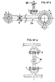
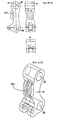
- Figure 1 is a profiled, plant view in elevation of the triangular support (1) to be fitted in the mounted farm implements (first model).
- Figure 2 is a profiled plant view in elevation of the support (2) for dragged farm implements and an assembly example of the part in the implement boom (3) (first model and second model).
- Figure 3 is a detail in elevation of the swinging arm (34) (first model).
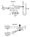
- Figure 4 is a detail of the tierod (36) linking the swinging arm (34) with the top arm (35) (first model).
- Figure 5 is a detail of the top arm (35), hydraulic cylinder (9) and hook (10) (first model).
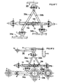
- Figure 6 is a partial plant view of the lower arm (34) and hydraulic cylinder (first model).
- Figure 7 is a perspective view of the hung takeoff (15) from the coupling structure (first model).
- Figure 8 is a perspective view of the coupling structure assembly arranged at the rear side of a tractor (first model).
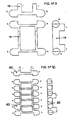
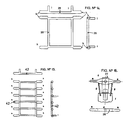
- Figure 9 is a profiled, plant view in elevation of the supporting structure (18) in the mounted farm implements (second model).
- Figure 10 is a profiled, plant view in elevation of a supporting variable (40) in the mounted farm implements. With the chance of securing at different heights (second model).
- Figure 11 is a plan view in elevation of the assembled swinging arm (38) excepting the cylinder (11) (second model).
- Figure 12 is a profiled, plant view in elevation of the coupling part (24) provided in the swinging arm (38) (second model).
- Figure 13 is a perspective view of the coupling part (24) provided in the swinging arm (38) (second model).
- Figure 14 is a profiled, plant view in elevation of the supporting structure (25) in the mounted farm implements (second improved model).
- Figure 15 is a profiled, plant view in elevation of the supporting structure (42) in the mounted farm implements, With the chance of securing to different heights (second improved model).
- Figure 16 is a profiled, plant view in elevation of the support (26) for dragged implements and an assembly example of the part in the boom (27) of the farm implement (second improved model).
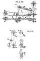
- Figure 17 is a plant view in elevation of the assembled swinging arm (41) excepting the cylinder (11) (second improved model).
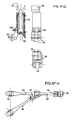
- Figure 18 is a profiled, plant view in elevation of the coupling part (29) provided in the swinging arm (41) (second improved model).
- Figure 19 is perspective view of the second invention model coupled to the structure of the shovel arranged at the front side of a tractor.
- Figure 20 is a profiled, plant view in elevation of the supporting structure (44) for the dragged farm implements (third model).
- Figure 21 is a view in elevation of the assembled swinging arm (43) (third model).
- Figure 22 is a profiled, plant view in elevation of the coupling part (32) provided in the swinging arm (43) (third model).
- Figure 23 is a plant view of the assembled swinging arm (43) (third model).
- Figure 24 is a plant view in elevation of the swinging arm (38) (second model).
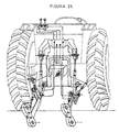
- Figure 25 is a perspective view of the automatic device anchoring fitted on the tractor.
- Figure 26 is a view in elevation of the arm (41) or (38) or (43) showing an alternative arrangement of the pivoting member (23) in the clamping part (29) or (24) or (32) (second or third models).
- the first model is suitable for tractors working with the sensible point relative to the effort at the third point.
- the displacement of the third anchoring point can widely be varied forwardly and rearwardly without any effort problems thereto.
- the second and third models are suitable for tractors working with the sensible point relative to the effort in the lower bars. That is, the lower bars bear a higher pressure of longitudinal traction or weight suspension, without calling for a requirement that third point had a large longitudinal effort or motion forwardly and rearwardly.
- Example of a preferred embodiment for the first development model Example of a preferred embodiment for the first development model.
- the vehicle provided with the new invention has a coupling device at its rear side comprising preferably three arms (34a, 34b, 35) (figure 3, figure 5) fitted to the chassis. At the lower side, two arms (34a, 34b) parallel and symmetrical with each other can be seen horizontally arranged and each pivoted to the chassis at an end (5) and with the possibility of vertically swinging.
- Each arm (34) is laterally related to a hydraulic cylinder (11) (figure 6), laterally and obliquely arranged, this hydraulic cylinder (11) being secured at an end to a ball joint (6) located at an intermediate point of said arm (34) and at the other end to a pivoting member (14) and to the vehicle chassis located at a colinear point with the cited shaft by the two couplings (5a, 5b) to the arms' chassis (34a, 34b).
- an implement securing support(4) is seen thereto.
- a third arm (35) (figure 5) is pivotedly fitted to the chassis (13), this arm having at its free end a telescopic hydraulic cylinder (9) showing at its end, a sliding hook (10) or fork.
- the top arm (35) is mechanically related with each one of the lower arms (34a, 34b) by means of two tierods (36a, 36b) (figure 4). These tierods (36a, 36b) are pivoted at their ends, at an intermediate point of each arm by means of ball joint (7a, 7b, 8), crossheads or similar.
- the mounted implement suitable for coupling with the cited system has at its front side a standardized structure comprising a frame (1) (figure 1) in the shape of an isosceles triangle having two horizontal elongations (a) at its base, one at each side, preferably with a cylindrical shape and topped by a hemisphere.
- the triangle (1) showed, at its top side, designed for fitting the arm associated to the third point, a rotating horizontal cylindrical bushing (b) which can be detached by means of a pin.
- Said triangular structure (1) showed several anchoring members (c) with the farm implement fully distributed.
- connection boom (3) (figure 2) with a transversal coupling comprising a bar (2) at its ends being provided with two cylindrical terminals (e) topped at the ends by a hemisphere suitable for being accepted by the tractor coupling (4), and at the intermediate point of said coupling a hole (d) is drilled for a vertically projecting bolt to go through from the boom (3) and a rotation is allowed according to a vertical shaft.
- the coupling (2) is kept perpendicularly to the boom (3) in the uncoupling position due to the action of the tensioning springs (g).
- the vehicle comprises a coupling device preferably at its rear side, provided with two equal arms (38a, 38b) (figure 11) and parallel and horizontally arranged fitted to the chassis by means of a ball joint (19a, 19b) and with the possibility of reciprocatingly swing and concurrently mutually being opened and closed.
- Each arm is related with a hydraulic cylinder at the holes (20), which deliver to both arms (38a, 38b) a upwardly and downwardly motion in a concurrent way.
- each arm (38a, 38b) is laterally associated with a laterally obliquely-arranged hydraulic cylinder (11) (figure 24), this hydraulic cylinder (11) being fitted by one end to a ball joint (21) located at an intermediate point of said arm (38) and to the other end with a pivoting member (3) placed at a colinear point with the cited shaft by the two couplings (19a, 19b) to the tractor chassis.
- a coupling part (24) with the implement is seen at the free end of each arm (38) .
- Said part (24) is pivoted to the arm (38) by means of the pivoting member (23) which allows to said part (24) to have a limited forwardly and rearwardly rotation.
- the coupling part (24) has elongated shape to the high, and two transversal and going through holes are drilled therein suitable to receive the supports (18) (figure 9) of the farm implement coupling.
- the part (24) having alongside a sliding groove (30a) run by a bolt or slider provided at the end of the hydraulic cylinder (22).
- Said hydraulic cylinder (22) is parallel to the arm (38) and fitted by its body with said arm (38).
- the free and projected arm towards the part (24) has at the end the previously cited bolt or slider inserted into the groove (30a) of the part (24).
- the pivoting member (23) existing at the coupling part (24) is placed at the same height that the lower hole (39) for tractors sensible to the efforts in the lower arms (38). But as an alternative construction for tractors sensible to the effort at the third point, the part (24) has said pivoting member (23) at an intermediate point which improved the effort distribution at the pair of holes (39) (figure 26).
- the mounted implement suitable to be coupled with the disclosed coupling device has to be provided at its front side with a standard coupling structure (18) (figure 9).
- This standard coupling structure (18) has the shape of a rectangular frame, having at each side, a pair of supports (h) horizontally projected in a cylindrical way with the topped end in a hemispherical shape or similar, suitable to nesting into the holes (39) drilled in the coupling part (24).
- the frame (18) having in turn four extensions (i) for welding or assembly on the farm implement.
- a similar structure (40) (figure 10) to the disclosed structure (18) arranged on the farm implement has been envisaged but substantially higher at the top and having several height-overlapped supporting sets at both sides, such as the tractor can be coupled in a supporting set (h) associated to the desirable height.
- connection boom (3) (figure 2) with a transversal coupling made up with a bar (2) having at its ends, two cylindrical terminals (e) topped at the ends by a hemisphere suitable for being accepted into the hole (39) of the part (24), at the intermediate point of said coupling is drilled a hole (d) to go through a vertically projecting bolt from the boom (3) allowing its rotation according to a vertical shaft.
- the coupling (2) is kept perpendicularly to the boom (3) in the uncoupling position due to the effect of two tensioning springs (g).
- the second development model accepts a modified embodiment providing mechanical simplicity and rigidity improvements.
- This second improved development model comprises two equal symmetrical and parallel arms (41a, 41b) (figure 17) similar to the arms (38a, 38b) but differentiated when the cylinder is embossed at a diverse position.
- the cylinder (22) has a pivoted end over a projecting support (45) perpendicularly to an intermediate area of said arm (41) and the opposite end of said cylinder (22) is pivoted in turn at a point (30b) of the coupling part (29).
- the holes (39) drilled at the coupling part (24) are replaced by drilled spheres (31) (figure 18). These drilled spheres having a counterweight for their stability.
- the embodiment of the second improved model accepts a modification of the pivoting member position (23) showed in the coupling part (29). It can be located at the same height than the lower hole (31) or as an alternative construction for tractors sensible to the effort in the third point, the part (29) having said pivoting member (23) at an intermediate point between both coupling spheres (31) (figure 26) improving effort distribution between said pair of spheres (31).
- the vehicle provided with the new invention has a coupling device at its rear side preferably comprising two symmetrical, parallel and mutually integrated arms (43) (figure 21) in a way that both have a concurrently vertical swinging motion.
- Each arm (42) having at the tractor's near end, a pivoting member (19) whereon said arm (43) is swinging.
- a hole (20) is drilled, at this point the hydraulic cylinder sensible for giving the vertical swinging motion to the arm is pivoted thereto.
- a vertically-projected support having a hydraulic cylinder (22) in a pivoting member (45), at its end, the opposite end of the cylinder is ramming a pivoting member (30b) at an intermediate point of the vertically-arranged part (22) which in turn is pivoted, at the lower part, with the arm (43) by means of the pivoting member (23).
- the coupling part (32) is basically made up with an extensible hydraulic cylinder having fork-like configurations at both ends.
- the mounted farm implement itself has at its front side, a coupling structure (44) (figure 20) comprising a rectangular frame with two supporting pairs (h) horizontally projecting from each side, and with a cylindrical shape provided with a hemispherical-rounded end.
- the frame having at its rear side, some projections or flanges (i) suitable to be integrated with the implement by welding o similar assembly.
- the same coupling structure (44) can be used which has at its center area, a transversally-located horizontal crossmember which at its intermediate point has a hole drilled suitable for a bolt to go through, this bolt placed at the end of the implement's boom (12) to allow its horizontal pivoting motion.
Landscapes
- Life Sciences & Earth Sciences (AREA)
- Engineering & Computer Science (AREA)
- Mechanical Engineering (AREA)
- Soil Sciences (AREA)
- Environmental Sciences (AREA)
- Zoology (AREA)
- Agricultural Machines (AREA)
- Lifting Devices For Agricultural Implements (AREA)
Applications Claiming Priority (2)
| Application Number | Priority Date | Filing Date | Title |
|---|---|---|---|
| ES009802701A ES2187307B1 (es) | 1998-12-29 | 1998-12-29 | Mecanismo automatico para el enganche universal de aperos agricolas y similares. |
| ES9802701 | 1998-12-29 |
Publications (2)
| Publication Number | Publication Date |
|---|---|
| EP1016340A2 true EP1016340A2 (fr) | 2000-07-05 |
| EP1016340A3 EP1016340A3 (fr) | 2004-07-07 |
Family
ID=8306230
Family Applications (1)
| Application Number | Title | Priority Date | Filing Date |
|---|---|---|---|
| EP99500242A Withdrawn EP1016340A3 (fr) | 1998-12-29 | 1999-12-15 | Dispositif automatique d'accouplement multifonctionnel pour outils agricoles ou équivalents |
Country Status (3)
| Country | Link |
|---|---|
| US (1) | US6352124B1 (fr) |
| EP (1) | EP1016340A3 (fr) |
| ES (1) | ES2187307B1 (fr) |
Cited By (3)
| Publication number | Priority date | Publication date | Assignee | Title |
|---|---|---|---|---|
| FR2857557A1 (fr) * | 2003-07-17 | 2005-01-21 | Deere & Co | Dispositif de couplage rapide avec elements de crochets doubles |
| FR2998522A1 (fr) * | 2012-11-26 | 2014-05-30 | Naturagriff Sarl | Chassis intermediaire avec centrale hydraulique incorporee et transmission multifonctionnelle |
| CN104981145A (zh) * | 2013-02-07 | 2015-10-14 | 库恩股份有限公司 | 带挂接装置的包括改进的回位装置的割草机 |
Families Citing this family (7)
| Publication number | Priority date | Publication date | Assignee | Title |
|---|---|---|---|---|
| US6293077B1 (en) * | 2000-05-02 | 2001-09-25 | Mtd Products Inc | Deck attachment and lift system |
| US20040071644A1 (en) * | 2002-07-08 | 2004-04-15 | Nathali Mougin | Nail varnish |
| WO2004080729A2 (fr) * | 2003-03-06 | 2004-09-23 | Nelson Christopher A | Raccord d'air tournant pour systeme de gonflage de pneus central |
| US7048070B2 (en) * | 2003-07-17 | 2006-05-23 | Deere & Company | Quick coupler assembly with dual hook members |
| GB201020863D0 (en) * | 2010-12-09 | 2011-01-26 | Agco Internat Ltd | Linkage rocker arm on an agricultural vehicle |
| CN109249755B (zh) * | 2018-10-30 | 2023-11-14 | 苏昶 | 一种独立悬挂辅助伸长装置 |
| US11589492B2 (en) * | 2020-02-28 | 2023-02-28 | Deere & Company | Stabilizer for a rear hitch |
Family Cites Families (12)
| Publication number | Priority date | Publication date | Assignee | Title |
|---|---|---|---|---|
| DE1270872B (de) * | 1964-11-28 | 1968-06-20 | Heinrich Weiste | Vorrichtung zum Kuppeln von Geraeten an Schlepper mit Kraftheber |
| GB1175371A (en) * | 1966-03-02 | 1969-12-23 | Massey Ferguson Perkins Ltd | Improvements in or relating to Tractor-Implement Hitches. |
| NL6614855A (fr) * | 1966-10-21 | 1968-04-22 | ||
| FR2061572B1 (fr) * | 1969-07-25 | 1973-03-16 | Renault | |
| US4519623A (en) * | 1983-05-09 | 1985-05-28 | Orthman Manufacturing, Inc. | Tractor front end hitch |
| DE8516603U1 (de) * | 1985-06-07 | 1986-02-27 | Müller, Rudolf, 7712 Blumberg | Fahrzeug zum Anhängen von land- oder forstwirtschaftlichen Zusatzgeräten |
| DE4118683C1 (fr) * | 1991-06-07 | 1992-05-27 | Jean Walterscheid Gmbh, 5204 Lohmar, De | |
| US5697454A (en) * | 1995-07-18 | 1997-12-16 | Wilcox Brothers Incorporated | Three-point hitch assembly |
| US5601146A (en) * | 1995-08-15 | 1997-02-11 | Case Corporation | Hitch assembly for a tractor |
| US5975216A (en) * | 1997-10-10 | 1999-11-02 | Tructor, Inc. | Low profile transferrable hydraulic three point hitch |
| US6089328A (en) * | 1998-08-28 | 2000-07-18 | Caterpillar, Inc. | Hitch assembly for a work machine |
| US6149180A (en) * | 1998-12-28 | 2000-11-21 | Haws; James E. | Longitudinally adjustable lift arm for a three-point hitch |
-
1998
- 1998-12-29 ES ES009802701A patent/ES2187307B1/es not_active Expired - Lifetime
-
1999
- 1999-12-15 EP EP99500242A patent/EP1016340A3/fr not_active Withdrawn
- 1999-12-28 US US09/473,069 patent/US6352124B1/en not_active Expired - Fee Related
Non-Patent Citations (1)
| Title |
|---|
| None |
Cited By (4)
| Publication number | Priority date | Publication date | Assignee | Title |
|---|---|---|---|---|
| FR2857557A1 (fr) * | 2003-07-17 | 2005-01-21 | Deere & Co | Dispositif de couplage rapide avec elements de crochets doubles |
| FR2998522A1 (fr) * | 2012-11-26 | 2014-05-30 | Naturagriff Sarl | Chassis intermediaire avec centrale hydraulique incorporee et transmission multifonctionnelle |
| CN104981145A (zh) * | 2013-02-07 | 2015-10-14 | 库恩股份有限公司 | 带挂接装置的包括改进的回位装置的割草机 |
| CN104981145B (zh) * | 2013-02-07 | 2017-04-26 | 库恩股份有限公司 | 带挂接装置的包括改进的回位装置的割草机 |
Also Published As
| Publication number | Publication date |
|---|---|
| EP1016340A3 (fr) | 2004-07-07 |
| US6352124B1 (en) | 2002-03-05 |
| ES2187307A1 (es) | 2003-06-01 |
| ES2187307B1 (es) | 2005-07-01 |
Similar Documents
| Publication | Publication Date | Title |
|---|---|---|
| US3948327A (en) | Wingfold configuration | |
| US4015855A (en) | Implement hitch | |
| US6443236B2 (en) | Three-point hitch for a tractor | |
| US6352124B1 (en) | Automatic device for all-purpose coupling of agricultural implements and the like | |
| US20120138321A1 (en) | Three-point front hitch mountable to the frame of an agricultural tractor | |
| US5566536A (en) | Mower-conditioner platform suspension including single upper arm and hydraulic cylinder for platform lift | |
| US8382207B2 (en) | Three point linkage systems | |
| US2786589A (en) | Implement carrier | |
| US4424982A (en) | Attachment device for a motor vehicle | |
| US6915862B2 (en) | Three point hitch for utility vehicle | |
| US2423148A (en) | Quick demountable cultivator | |
| US2834277A (en) | Quick hitch system | |
| US2750724A (en) | Harrow hitch | |
| KR101973947B1 (ko) | 승용관리기용 작업기 연결장치 | |
| US6533042B1 (en) | Attachment for tractor | |
| US20070098538A1 (en) | Mount apparatus and method for attaching three-point hitch implements to front arms of a front-end loader | |
| US6663338B1 (en) | Three-point hitch loader | |
| CA2391471C (fr) | Support de repos de debroussailleuse rotative | |
| US4214636A (en) | Three-point hitch adapter | |
| JP2002191204A (ja) | 農用トラクタの作業機連結装置 | |
| US4340239A (en) | Farm implement with two-way hitch | |
| US2962104A (en) | Quick-hitch means for attaching agricultural implements to a tractor | |
| WO2004056168A1 (fr) | Systeme d'attelage automatise | |
| CN212463960U (zh) | 独立式三点悬挂装置 | |
| JPH0623204Y2 (ja) | 牽引型農作業機の連結装置 |
Legal Events
| Date | Code | Title | Description |
|---|---|---|---|
| PUAI | Public reference made under article 153(3) epc to a published international application that has entered the european phase |
Free format text: ORIGINAL CODE: 0009012 |
|
| AK | Designated contracting states |
Kind code of ref document: A2 Designated state(s): AT BE CH CY DE DK ES FI FR GB GR IE IT LI LU MC NL PT SE |
|
| AX | Request for extension of the european patent |
Free format text: AL;LT;LV;MK;RO;SI |
|
| RIC1 | Information provided on ipc code assigned before grant |
Ipc: 7A 01B 59/041 B Ipc: 7A 01B 59/00 B Ipc: 7A 01B 59/06 A |
|
| PUAL | Search report despatched |
Free format text: ORIGINAL CODE: 0009013 |
|
| AK | Designated contracting states |
Kind code of ref document: A3 Designated state(s): AT BE CH CY DE DK ES FI FR GB GR IE IT LI LU MC NL PT SE |
|
| AX | Request for extension of the european patent |
Extension state: AL LT LV MK RO SI |
|
| STAA | Information on the status of an ep patent application or granted ep patent |
Free format text: STATUS: THE APPLICATION IS DEEMED TO BE WITHDRAWN |
|
| 18D | Application deemed to be withdrawn |
Effective date: 20040701 |