EP1016494A2 - Procédé et dispositif d'usinage de materiaux au laser sous gaz protecteur avec différents flux volumiques comme protection d'optique - Google Patents
Procédé et dispositif d'usinage de materiaux au laser sous gaz protecteur avec différents flux volumiques comme protection d'optique Download PDFInfo
- Publication number
- EP1016494A2 EP1016494A2 EP99125817A EP99125817A EP1016494A2 EP 1016494 A2 EP1016494 A2 EP 1016494A2 EP 99125817 A EP99125817 A EP 99125817A EP 99125817 A EP99125817 A EP 99125817A EP 1016494 A2 EP1016494 A2 EP 1016494A2
- Authority
- EP
- European Patent Office
- Prior art keywords
- nozzle
- protective gas
- flow
- gas
- laser
- Prior art date
- Legal status (The legal status is an assumption and is not a legal conclusion. Google has not performed a legal analysis and makes no representation as to the accuracy of the status listed.)
- Withdrawn
Links
Images
Classifications
-
- B—PERFORMING OPERATIONS; TRANSPORTING
- B23—MACHINE TOOLS; METAL-WORKING NOT OTHERWISE PROVIDED FOR
- B23K—SOLDERING OR UNSOLDERING; WELDING; CLADDING OR PLATING BY SOLDERING OR WELDING; CUTTING BY APPLYING HEAT LOCALLY, e.g. FLAME CUTTING; WORKING BY LASER BEAM
- B23K26/00—Working by laser beam, e.g. welding, cutting or boring
- B23K26/14—Working by laser beam, e.g. welding, cutting or boring using a fluid stream, e.g. a jet of gas, in conjunction with the laser beam; Nozzles therefor
- B23K26/1435—Working by laser beam, e.g. welding, cutting or boring using a fluid stream, e.g. a jet of gas, in conjunction with the laser beam; Nozzles therefor involving specially adapted flow-control means
-
- B—PERFORMING OPERATIONS; TRANSPORTING
- B23—MACHINE TOOLS; METAL-WORKING NOT OTHERWISE PROVIDED FOR
- B23K—SOLDERING OR UNSOLDERING; WELDING; CLADDING OR PLATING BY SOLDERING OR WELDING; CUTTING BY APPLYING HEAT LOCALLY, e.g. FLAME CUTTING; WORKING BY LASER BEAM
- B23K26/00—Working by laser beam, e.g. welding, cutting or boring
- B23K26/14—Working by laser beam, e.g. welding, cutting or boring using a fluid stream, e.g. a jet of gas, in conjunction with the laser beam; Nozzles therefor
-
- B—PERFORMING OPERATIONS; TRANSPORTING
- B23—MACHINE TOOLS; METAL-WORKING NOT OTHERWISE PROVIDED FOR
- B23K—SOLDERING OR UNSOLDERING; WELDING; CLADDING OR PLATING BY SOLDERING OR WELDING; CUTTING BY APPLYING HEAT LOCALLY, e.g. FLAME CUTTING; WORKING BY LASER BEAM
- B23K26/00—Working by laser beam, e.g. welding, cutting or boring
- B23K26/14—Working by laser beam, e.g. welding, cutting or boring using a fluid stream, e.g. a jet of gas, in conjunction with the laser beam; Nozzles therefor
- B23K26/1435—Working by laser beam, e.g. welding, cutting or boring using a fluid stream, e.g. a jet of gas, in conjunction with the laser beam; Nozzles therefor involving specially adapted flow-control means
- B23K26/1438—Working by laser beam, e.g. welding, cutting or boring using a fluid stream, e.g. a jet of gas, in conjunction with the laser beam; Nozzles therefor involving specially adapted flow-control means for directional control
-
- B—PERFORMING OPERATIONS; TRANSPORTING
- B23—MACHINE TOOLS; METAL-WORKING NOT OTHERWISE PROVIDED FOR
- B23K—SOLDERING OR UNSOLDERING; WELDING; CLADDING OR PLATING BY SOLDERING OR WELDING; CUTTING BY APPLYING HEAT LOCALLY, e.g. FLAME CUTTING; WORKING BY LASER BEAM
- B23K26/00—Working by laser beam, e.g. welding, cutting or boring
- B23K26/14—Working by laser beam, e.g. welding, cutting or boring using a fluid stream, e.g. a jet of gas, in conjunction with the laser beam; Nozzles therefor
- B23K26/1462—Nozzles; Features related to nozzles
- B23K26/1464—Supply to, or discharge from, nozzles of media, e.g. gas, powder, wire
- B23K26/1476—Features inside the nozzle for feeding the fluid stream through the nozzle
-
- B—PERFORMING OPERATIONS; TRANSPORTING
- B23—MACHINE TOOLS; METAL-WORKING NOT OTHERWISE PROVIDED FOR
- B23K—SOLDERING OR UNSOLDERING; WELDING; CLADDING OR PLATING BY SOLDERING OR WELDING; CUTTING BY APPLYING HEAT LOCALLY, e.g. FLAME CUTTING; WORKING BY LASER BEAM
- B23K26/00—Working by laser beam, e.g. welding, cutting or boring
- B23K26/14—Working by laser beam, e.g. welding, cutting or boring using a fluid stream, e.g. a jet of gas, in conjunction with the laser beam; Nozzles therefor
- B23K26/1462—Nozzles; Features related to nozzles
- B23K26/1488—Means for protecting nozzles, e.g. the tip surface
Definitions
- the invention relates to a method for laser material processing, wherein a focused Laser beam is guided onto the workpiece to be machined and the optics in the Laser material processing head is protected with the help of a gas stream.
- the invention further relates to a device for laser material processing, which means for guiding a focused laser beam onto a workpiece to be machined and Means for protecting the optics in the laser material processing head with the help of a gas stream includes.
- a focused laser beam essentially becomes a understood laser beam focused on the workpiece surface. Except for the predominantly used method with a focus on the workpiece surface The invention cannot use laser radiation even in the rarely used variant radiation focused precisely on the workpiece surface can be applied.
- the laser processing systems are known per se. As a rule, they have a laser processing head, possibly with a Laser beam coaxially arranged nozzle. Laser processing systems are often used used in conjunction with a CNC control.
- the main laser processing methods are laser beam welding and laser beam cutting and methods of laser beam surface treatment are known.
- the Laser beam cutting is differentiated between three process variants, the Laser beam flame cutting, laser beam fusion cutting and laser beam sublimation cutting.
- the process of laser beam surface treatment include above all laser beam hardening, laser beam remelting, laser beam alloying, laser beam coating and laser beam drilling.
- the proceedings laser beam surface treatment are usually used where conventional surface processes are not used or only with great disadvantages can be.
- the high energy of the laser beam is used in the processes listed Material of the workpiece to be machined is heated, melted or evaporated.
- Protective and / or process gases are usually used in laser material processing or working gases are used. Depending on the process and what is to be processed Material, the gases used can have different tasks. For example, the use of a hard gas jet results in a laser cut Covering with protective gas can create a weld, a trace of hardness, a trace around molten material, a label, an engraving or the like become.
- metallic and / or other material heated to temperatures at which a reaction with the enveloping gases In many cases, this becomes technical gases used to make these material processing processes more effective, faster and / or with to be able to perform improved quality.
- Laser welding (usually using a laser welding head) is used Considered below as representative of laser material processing.
- the welding process often creates splashes, which move away from the workpiece and contaminate the laser optics.
- the laser optics are lenses, but also mirrors or others optical elements addressed.
- shielding gases are primarily used to cover the weld seam by using protective gas. Because with many methods of laser material processing metallic and / or other material is heated to temperatures at which react with the enveloping gases. In many cases technical gases are used to make these material processing processes more effective, to be able to perform faster and / or with improved quality.
- the protective gases are primarily intended to prevent laser welding seams For example, in the case of stainless steel welding, they are oxidized and then reworked must be that welds contain pores or that others quality-reducing characteristics occur.
- the present invention is therefore based on the object of a method and Show device of the type mentioned, in which the material processing is improved by means of laser with a view to protecting the optics.
- coaxial protective gases should be made possible. It will be a Processing under stable process parameters (e.g. beam quality, protective gas purity) sought. In principle, the use of different protective gases should not be used be restricted.
- This object is achieved for the method in that the Inert gas in a first region of the nozzle channel in the direction of flow Laser beam coaxial nozzle guided as a coaxial jet to protect the optics and the protective gas with a reduced volume flow via a flow direction second area of the nozzle channel of the nozzle against the surface of the workpiece is directed.
- This object is achieved for the device in that a in Direction of flow of the first region of a nozzle channel one coaxial to the laser beam arranged nozzle for guiding protective gas as a coaxial jet to protect the optics and means for reducing the volume flow of the protective gas in an in Direction of flow second area of the nozzle channel of the nozzle opposite the Volume flow of the protective gas in the first region of the nozzle channel in the direction of flow the nozzle are provided.
- the Shielding gas fulfills two functions: On the one hand, shielding gas also provides comparatively large volume flow for effective protection of the optics. On the other hand, a comparatively low volume flow of protective gas fulfills the actual purpose of the cover during the welding process.
- Mirror optics can also be used within the scope of the invention. At low Laser powers can be used to ensure gas tightness on the workpiece Optics can be used.
- the protective gas is the first in the flow direction Area of the nozzle channel of the nozzle with a comparatively high flow rate to protect the optics and the shielding gas with reduced flow velocity directed against the surface of the workpiece.
- the protective gas is partially in the laser material processing head over a or several gas channels are circulated. This allows the amount of shielding gas required be reduced.
- means for the partial suction of protective gas provided from the first region of the nozzle channel of the nozzle.
- These can in particular Means for generating a flow of inert gas in the first region of the Include nozzle channel of the nozzle acting centrifugal force.
- A preferably serves Impeller for generating centrifugal force.
- the impeller can for example an electric motor, for example in connection with gear wheels or a toothed belt a magnetic or pneumatic drive can be moved.
- impeller is possible, the speed and / or the Position of the wings can be varied. This allows, for example, the choice whether more gas is drawn in from the optics or also from the workpiece should.
- Means for cleaning and / or cooling the protective gas in particular be provided for the gas channel or channels of the circuit.
- the invention can be used in connection with all types of lasers. Above all, it is suitable for use in laser processing with Nd-YAG lasers, Eximer lasers, diode lasers and CO 2 lasers.
- Inert gases such as argon are particularly suitable as protective gases for laser welding, Neon and helium, but also for example nitrogen, oxygen, carbon dioxide, Hydrogen, hydrocarbons and the mixtures of the aforementioned gases.
- the invention can also be used in connection with other laser processing methods can be used to advantage (for example when laser cutting).
- laser processing methods cutting, drilling, remelting, removing, sintering and / or hardening Use of a laser in question.
- the invention also enables the use of radiation sources other than lasers.
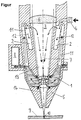
- the laser welding head shown in FIG. 1 has a lens 6 for focusing the Laser beam 3 on.
- Protective gas is supplied via the protective gas feed 4.
- the Shielding gas flows in a first region 13 of the nozzle channel in the direction of flow the nozzle 5 arranged coaxially to the laser beam as a coaxial jet 7 with comparatively high flow velocity. This serves to protect the optics 6.
- the protective gas is against the surface of the workpiece with reduced flow velocity 9, namely the welding process 10.
- An impeller 1 is installed between the laser optics 6 and the welding process 10, whose axis of rotation is coaxial with the laser beam 3.
- the impeller 1 also rotates a sufficiently high speed (the rotation is indicated by arrows), so that by the centrifugal force the gas 7 from the center (in the flow direction first Area 13 of the central nozzle channel) and sucked off by the impeller 1 is pressed outside. From there through the design of the gas channels 11 Gas flow first against the beam direction of the laser beam 3 and then - tight under the optics 6 - back into the beam path and down towards the laser radiation 3 is deflected.
- Shielding gas supplied under the optics flow through the area between the protective gas nozzle 5 and the optics 6 very often until it leaves the welding head through the protective gas nozzle 5 for the welding process 10.
- the protective gas is compared to the first region 13 of the flow direction Nozzle channel of the nozzle 5 reduced volume flow in the direction of flow second area 14 of the nozzle channel of the nozzle 5 against the surface of the workpiece 9 headed.
- the flow rate and thus the protective effect for the optics can be achieved by the speed of the impeller 1 can be determined and optimized.
- Splashes 12 flying in through the protective gas nozzle 5 are discharged through the coaxial jet 7 prevented from reaching lens 6.
- Splashes 12 are either by the Coaxial jet 7 is again pressed in the direction of workpiece 9 out of the protective gas nozzle 5 or sucked out of the central nozzle duct by the impeller 1 and in the splash trap 2 collected. Due to the different centrifugal forces on gas and material splashes 12, the splashes 12 can be extracted relatively easily from the protective gas and be collected.
- Figure 1 is a drive 8 (electric motor) with coupling via gears to the Impeller shown.
- the optics reliably protect and maintain the purity of the shielding gases used.
Landscapes
- Physics & Mathematics (AREA)
- Optics & Photonics (AREA)
- Engineering & Computer Science (AREA)
- Plasma & Fusion (AREA)
- Mechanical Engineering (AREA)
- Laser Beam Processing (AREA)
Applications Claiming Priority (2)
| Application Number | Priority Date | Filing Date | Title |
|---|---|---|---|
| DE19900001 | 1999-01-01 | ||
| DE19900001 | 1999-01-01 |
Publications (1)
| Publication Number | Publication Date |
|---|---|
| EP1016494A2 true EP1016494A2 (fr) | 2000-07-05 |
Family
ID=7893520
Family Applications (1)
| Application Number | Title | Priority Date | Filing Date |
|---|---|---|---|
| EP99125817A Withdrawn EP1016494A2 (fr) | 1999-01-01 | 1999-12-23 | Procédé et dispositif d'usinage de materiaux au laser sous gaz protecteur avec différents flux volumiques comme protection d'optique |
Country Status (2)
| Country | Link |
|---|---|
| EP (1) | EP1016494A2 (fr) |
| DE (1) | DE19962625A1 (fr) |
Cited By (5)
| Publication number | Priority date | Publication date | Assignee | Title |
|---|---|---|---|---|
| WO2014191463A1 (fr) * | 2013-05-29 | 2014-12-04 | Reis Group Holding Gmbh & Co. Kg | Dispositif à jet transversal et procédé d'évacuation de contaminants |
| CN110039175A (zh) * | 2019-05-29 | 2019-07-23 | 武汉奥森迪科智能科技股份有限公司 | 一种激光切割头喷嘴导气装置 |
| US11484970B2 (en) | 2017-02-21 | 2022-11-01 | General Electric Company | Additive manufacturing system and method of forming an object in a powder bed |
| US12042866B2 (en) | 2021-03-16 | 2024-07-23 | General Electric Company | Additive manufacturing apparatus and fluid flow mechanism |
| CN118989663A (zh) * | 2024-10-25 | 2024-11-22 | 江苏友发钢管有限公司 | 一种激光切割头及其切割装置 |
Families Citing this family (3)
| Publication number | Priority date | Publication date | Assignee | Title |
|---|---|---|---|---|
| DE102005030067A1 (de) | 2005-06-27 | 2006-12-28 | FHS Hochschule für Technik, Wirtschaft und soziale Arbeit St. Gallen | Verfahren und Vorrichtung zur Herstellung eines dreidimensionalen Gegenstandes durch ein generatives 3D-Verfahren |
| DE102006045554A1 (de) * | 2006-09-25 | 2008-04-03 | Keysystech Gmbh | Schutzvorrichtung für die Optik eines Laserschweißscanners |
| DE102011121697B4 (de) | 2011-12-16 | 2016-04-14 | Precitec Kg | Laserbearbeitungsvorrichtung zur Bearbeitung eines Werkstücks mittels eines Laserstrahls |
-
1999
- 1999-12-23 DE DE19962625A patent/DE19962625A1/de not_active Withdrawn
- 1999-12-23 EP EP99125817A patent/EP1016494A2/fr not_active Withdrawn
Cited By (8)
| Publication number | Priority date | Publication date | Assignee | Title |
|---|---|---|---|---|
| WO2014191463A1 (fr) * | 2013-05-29 | 2014-12-04 | Reis Group Holding Gmbh & Co. Kg | Dispositif à jet transversal et procédé d'évacuation de contaminants |
| US10092981B2 (en) | 2013-05-29 | 2018-10-09 | Kuka Deutschland Gmbh | Crossjet assembly and method for carrying away contaminants |
| US11484970B2 (en) | 2017-02-21 | 2022-11-01 | General Electric Company | Additive manufacturing system and method of forming an object in a powder bed |
| US12059748B2 (en) | 2017-02-21 | 2024-08-13 | General Electric Company | Additive manufacturing system and method of forming an object in a powder bed |
| CN110039175A (zh) * | 2019-05-29 | 2019-07-23 | 武汉奥森迪科智能科技股份有限公司 | 一种激光切割头喷嘴导气装置 |
| CN110039175B (zh) * | 2019-05-29 | 2024-05-17 | 武汉奥森迪科智能科技股份有限公司 | 一种激光切割头喷嘴导气装置 |
| US12042866B2 (en) | 2021-03-16 | 2024-07-23 | General Electric Company | Additive manufacturing apparatus and fluid flow mechanism |
| CN118989663A (zh) * | 2024-10-25 | 2024-11-22 | 江苏友发钢管有限公司 | 一种激光切割头及其切割装置 |
Also Published As
| Publication number | Publication date |
|---|---|
| DE19962625A1 (de) | 2000-07-06 |
Similar Documents
| Publication | Publication Date | Title |
|---|---|---|
| EP1016493A2 (fr) | Procédé et dispositif d'usinage de matériaux au laser sous gaz protecteur avec vélocité différente comme protection d'optique | |
| EP1607167B1 (fr) | Sytème cross-jet pour soudage laser hybride | |
| DE60314758T2 (de) | Laserschweissverfahren zur plasmaverhinderung | |
| DE19948895B4 (de) | Laserschweisseinrichtung | |
| EP3965990B1 (fr) | Procédé et dispositif de traitement au laser d'une pièce | |
| EP0655021B1 (fr) | Procede de decoupage au laser de pieces a usiner se presentant sous forme de bandes ou de plaques, notamment de tole electrique | |
| DE10226359B4 (de) | Laserbearbeitungskopf zur Bearbeitung, insbesondere zum Schneiden eines Werkstücks mittels Laserstrahl | |
| EP4035823A1 (fr) | Procédé d'usinage par faisceau d'une pièce tabulaire ou tubulaire | |
| EP0458180B1 (fr) | Procédé et dispositif pour couper par rayon laser | |
| EP1016494A2 (fr) | Procédé et dispositif d'usinage de materiaux au laser sous gaz protecteur avec différents flux volumiques comme protection d'optique | |
| EP0600250B1 (fr) | Procédé pour le soudage de pièces d'oeuvre par un rayon laser et buse de soudage à laser | |
| EP1022087B1 (fr) | Soudage au laser avec gaz de traitement | |
| DE102018108824A1 (de) | Verfahren und Vorrichtung zum Laserschweißen | |
| EP1365883B1 (fr) | Soudage au laser de metaux non ferreux au moyen de diodes laser en presence d'un gaz de traitement | |
| DE19905739A1 (de) | Verfahren und Vorrichtung zur Lasermaterialbearbeitung mit koaxialem Gasstrom | |
| DE2211195A1 (de) | Verfahren und Vorrichtung zur Materialschweißung | |
| EP1016492A2 (fr) | Usinage de pièces sous gaz de traitement et sous gaz protecteur | |
| WO2005099959A1 (fr) | Procede et buse d'usinage ou d'analyse d'une piece ou d'un echantillon par un rayon energetique | |
| EP1339525A1 (fr) | Gaz de processus et procede de soudage au laser | |
| DE19858681A1 (de) | Vehrfahren und Vorrichtug zur Lasermaterialbearbeitung mit einem Gasstrom geringer Strömungsgeschwindigkeit | |
| DE2536573C3 (de) | Verfahren zum Schneiden von Werkstücken mittels aus dem Schneidkopf eines CO2 -Lasers austretender Laser- und Gasstrahlen | |
| EP1022086A2 (fr) | Soudage au laser avec gaz de traitement | |
| DE19616844A1 (de) | Verfahren zum Laserbeschichten sowie zum Laserschweißen von metallischen Werkstücken | |
| DE10203452B4 (de) | Vorrichtung zur Bearbeitung eines Werkstückes mit einem Laserstrahl | |
| DE19858684A1 (de) | Verfahren und Vorrichtung zur Lasermaterialbearbeitung mit großflächigem Gasstrom |
Legal Events
| Date | Code | Title | Description |
|---|---|---|---|
| PUAI | Public reference made under article 153(3) epc to a published international application that has entered the european phase |
Free format text: ORIGINAL CODE: 0009012 |
|
| AK | Designated contracting states |
Kind code of ref document: A2 Designated state(s): AT BE CH CY DE DK ES FI FR GB GR IE IT LI LU MC NL PT SE |
|
| AX | Request for extension of the european patent |
Free format text: AL;LT;LV;MK;RO;SI |
|
| RAP1 | Party data changed (applicant data changed or rights of an application transferred) |
Owner name: LINDE GAS AG |
|
| RAP1 | Party data changed (applicant data changed or rights of an application transferred) |
Owner name: LINDE AG |
|
| STAA | Information on the status of an ep patent application or granted ep patent |
Free format text: STATUS: THE APPLICATION IS DEEMED TO BE WITHDRAWN |
|
| 18D | Application deemed to be withdrawn |
Effective date: 20020702 |