EP1016573A2 - In einem elektrohydraulischen Steuergerät integrierter Drucksensor - Google Patents
In einem elektrohydraulischen Steuergerät integrierter Drucksensor Download PDFInfo
- Publication number
- EP1016573A2 EP1016573A2 EP99126060A EP99126060A EP1016573A2 EP 1016573 A2 EP1016573 A2 EP 1016573A2 EP 99126060 A EP99126060 A EP 99126060A EP 99126060 A EP99126060 A EP 99126060A EP 1016573 A2 EP1016573 A2 EP 1016573A2
- Authority
- EP
- European Patent Office
- Prior art keywords
- sensor
- valve body
- bore
- pressure
- base portion
- Prior art date
- Legal status (The legal status is an assumption and is not a legal conclusion. Google has not performed a legal analysis and makes no representation as to the accuracy of the status listed.)
- Granted
Links
Images


Classifications
-
- F—MECHANICAL ENGINEERING; LIGHTING; HEATING; WEAPONS; BLASTING
- F15—FLUID-PRESSURE ACTUATORS; HYDRAULICS OR PNEUMATICS IN GENERAL
- F15B—SYSTEMS ACTING BY MEANS OF FLUIDS IN GENERAL; FLUID-PRESSURE ACTUATORS, e.g. SERVOMOTORS; DETAILS OF FLUID-PRESSURE SYSTEMS, NOT OTHERWISE PROVIDED FOR
- F15B13/00—Details of servomotor systems ; Valves for servomotor systems
- F15B13/02—Fluid distribution or supply devices characterised by their adaptation to the control of servomotors
- F15B13/06—Fluid distribution or supply devices characterised by their adaptation to the control of servomotors for use with two or more servomotors
- F15B13/08—Assemblies of units, each for the control of a single servomotor only
- F15B13/0803—Modular units
-
- B—PERFORMING OPERATIONS; TRANSPORTING
- B60—VEHICLES IN GENERAL
- B60T—VEHICLE BRAKE CONTROL SYSTEMS OR PARTS THEREOF; BRAKE CONTROL SYSTEMS OR PARTS THEREOF, IN GENERAL; ARRANGEMENT OF BRAKING ELEMENTS ON VEHICLES IN GENERAL; PORTABLE DEVICES FOR PREVENTING UNWANTED MOVEMENT OF VEHICLES; VEHICLE MODIFICATIONS TO FACILITATE COOLING OF BRAKES
- B60T8/00—Arrangements for adjusting wheel-braking force to meet varying vehicular or ground-surface conditions, e.g. limiting or varying distribution of braking force
- B60T8/32—Arrangements for adjusting wheel-braking force to meet varying vehicular or ground-surface conditions, e.g. limiting or varying distribution of braking force responsive to a speed condition, e.g. acceleration or deceleration
- B60T8/34—Arrangements for adjusting wheel-braking force to meet varying vehicular or ground-surface conditions, e.g. limiting or varying distribution of braking force responsive to a speed condition, e.g. acceleration or deceleration having a fluid pressure regulator responsive to a speed condition
- B60T8/36—Arrangements for adjusting wheel-braking force to meet varying vehicular or ground-surface conditions, e.g. limiting or varying distribution of braking force responsive to a speed condition, e.g. acceleration or deceleration having a fluid pressure regulator responsive to a speed condition including a pilot valve responding to an electromagnetic force
- B60T8/3615—Electromagnetic valves specially adapted for anti-lock brake and traction control systems
- B60T8/3675—Electromagnetic valves specially adapted for anti-lock brake and traction control systems integrated in modulator units
-
- F—MECHANICAL ENGINEERING; LIGHTING; HEATING; WEAPONS; BLASTING
- F15—FLUID-PRESSURE ACTUATORS; HYDRAULICS OR PNEUMATICS IN GENERAL
- F15B—SYSTEMS ACTING BY MEANS OF FLUIDS IN GENERAL; FLUID-PRESSURE ACTUATORS, e.g. SERVOMOTORS; DETAILS OF FLUID-PRESSURE SYSTEMS, NOT OTHERWISE PROVIDED FOR
- F15B11/00—Servomotor systems without provision for follow-up action; Circuits therefor
- F15B11/02—Systems essentially incorporating special features for controlling the speed or actuating force of an output member
- F15B11/028—Systems essentially incorporating special features for controlling the speed or actuating force of an output member for controlling the actuating force
-
- G—PHYSICS
- G01—MEASURING; TESTING
- G01L—MEASURING FORCE, STRESS, TORQUE, WORK, MECHANICAL POWER, MECHANICAL EFFICIENCY, OR FLUID PRESSURE
- G01L19/00—Details of, or accessories for, apparatus for measuring steady or quasi-steady pressure of a fluent medium insofar as such details or accessories are not special to particular types of pressure gauges
- G01L19/0007—Fluidic connecting means
-
- G—PHYSICS
- G01—MEASURING; TESTING
- G01L—MEASURING FORCE, STRESS, TORQUE, WORK, MECHANICAL POWER, MECHANICAL EFFICIENCY, OR FLUID PRESSURE
- G01L19/00—Details of, or accessories for, apparatus for measuring steady or quasi-steady pressure of a fluent medium insofar as such details or accessories are not special to particular types of pressure gauges
- G01L19/0007—Fluidic connecting means
- G01L19/003—Fluidic connecting means using a detachable interface or adapter between the process medium and the pressure gauge
-
- G—PHYSICS
- G01—MEASURING; TESTING
- G01L—MEASURING FORCE, STRESS, TORQUE, WORK, MECHANICAL POWER, MECHANICAL EFFICIENCY, OR FLUID PRESSURE
- G01L19/00—Details of, or accessories for, apparatus for measuring steady or quasi-steady pressure of a fluent medium insofar as such details or accessories are not special to particular types of pressure gauges
- G01L19/0061—Electrical connection means
- G01L19/0084—Electrical connection means to the outside of the housing
-
- G—PHYSICS
- G01—MEASURING; TESTING
- G01L—MEASURING FORCE, STRESS, TORQUE, WORK, MECHANICAL POWER, MECHANICAL EFFICIENCY, OR FLUID PRESSURE
- G01L19/00—Details of, or accessories for, apparatus for measuring steady or quasi-steady pressure of a fluent medium insofar as such details or accessories are not special to particular types of pressure gauges
- G01L19/06—Means for preventing overload or deleterious influence of the measured medium on the measuring device or vice versa
- G01L19/0627—Protection against aggressive medium in general
- G01L19/0645—Protection against aggressive medium in general using isolation membranes, specially adapted for protection
-
- G—PHYSICS
- G01—MEASURING; TESTING
- G01L—MEASURING FORCE, STRESS, TORQUE, WORK, MECHANICAL POWER, MECHANICAL EFFICIENCY, OR FLUID PRESSURE
- G01L19/00—Details of, or accessories for, apparatus for measuring steady or quasi-steady pressure of a fluent medium insofar as such details or accessories are not special to particular types of pressure gauges
- G01L19/14—Housings
-
- G—PHYSICS
- G01—MEASURING; TESTING
- G01L—MEASURING FORCE, STRESS, TORQUE, WORK, MECHANICAL POWER, MECHANICAL EFFICIENCY, OR FLUID PRESSURE
- G01L19/00—Details of, or accessories for, apparatus for measuring steady or quasi-steady pressure of a fluent medium insofar as such details or accessories are not special to particular types of pressure gauges
- G01L19/14—Housings
- G01L19/142—Multiple part housings
-
- G—PHYSICS
- G01—MEASURING; TESTING
- G01L—MEASURING FORCE, STRESS, TORQUE, WORK, MECHANICAL POWER, MECHANICAL EFFICIENCY, OR FLUID PRESSURE
- G01L19/00—Details of, or accessories for, apparatus for measuring steady or quasi-steady pressure of a fluent medium insofar as such details or accessories are not special to particular types of pressure gauges
- G01L19/14—Housings
- G01L19/147—Details about the mounting of the sensor to support or covering means
-
- G—PHYSICS
- G01—MEASURING; TESTING
- G01L—MEASURING FORCE, STRESS, TORQUE, WORK, MECHANICAL POWER, MECHANICAL EFFICIENCY, OR FLUID PRESSURE
- G01L19/00—Details of, or accessories for, apparatus for measuring steady or quasi-steady pressure of a fluent medium insofar as such details or accessories are not special to particular types of pressure gauges
- G01L19/14—Housings
- G01L19/148—Details about the circuit board integration, e.g. integrated with the diaphragm surface or encapsulation
-
- G—PHYSICS
- G01—MEASURING; TESTING
- G01L—MEASURING FORCE, STRESS, TORQUE, WORK, MECHANICAL POWER, MECHANICAL EFFICIENCY, OR FLUID PRESSURE
- G01L9/00—Measuring steady of quasi-steady pressure of fluid or fluent solid material by electric or magnetic pressure-sensitive elements; Transmitting or indicating the displacement of mechanical pressure-sensitive elements, used to measure the steady or quasi-steady pressure of a fluid or fluent solid material, by electric or magnetic means
- G01L9/0041—Transmitting or indicating the displacement of flexible diaphragms
- G01L9/0051—Transmitting or indicating the displacement of flexible diaphragms using variations in ohmic resistance
-
- G—PHYSICS
- G01—MEASURING; TESTING
- G01L—MEASURING FORCE, STRESS, TORQUE, WORK, MECHANICAL POWER, MECHANICAL EFFICIENCY, OR FLUID PRESSURE
- G01L9/00—Measuring steady of quasi-steady pressure of fluid or fluent solid material by electric or magnetic pressure-sensitive elements; Transmitting or indicating the displacement of mechanical pressure-sensitive elements, used to measure the steady or quasi-steady pressure of a fluid or fluent solid material, by electric or magnetic means
- G01L9/0041—Transmitting or indicating the displacement of flexible diaphragms
- G01L9/0072—Transmitting or indicating the displacement of flexible diaphragms using variations in capacitance
-
- F—MECHANICAL ENGINEERING; LIGHTING; HEATING; WEAPONS; BLASTING
- F15—FLUID-PRESSURE ACTUATORS; HYDRAULICS OR PNEUMATICS IN GENERAL
- F15B—SYSTEMS ACTING BY MEANS OF FLUIDS IN GENERAL; FLUID-PRESSURE ACTUATORS, e.g. SERVOMOTORS; DETAILS OF FLUID-PRESSURE SYSTEMS, NOT OTHERWISE PROVIDED FOR
- F15B2211/00—Circuits for servomotor systems
- F15B2211/20—Fluid pressure source, e.g. accumulator or variable axial piston pump
- F15B2211/25—Pressure control functions
-
- F—MECHANICAL ENGINEERING; LIGHTING; HEATING; WEAPONS; BLASTING
- F15—FLUID-PRESSURE ACTUATORS; HYDRAULICS OR PNEUMATICS IN GENERAL
- F15B—SYSTEMS ACTING BY MEANS OF FLUIDS IN GENERAL; FLUID-PRESSURE ACTUATORS, e.g. SERVOMOTORS; DETAILS OF FLUID-PRESSURE SYSTEMS, NOT OTHERWISE PROVIDED FOR
- F15B2211/00—Circuits for servomotor systems
- F15B2211/50—Pressure control
- F15B2211/505—Pressure control characterised by the type of pressure control means
- F15B2211/50554—Pressure control characterised by the type of pressure control means the pressure control means controlling a pressure downstream of the pressure control means, e.g. pressure reducing valve
-
- F—MECHANICAL ENGINEERING; LIGHTING; HEATING; WEAPONS; BLASTING
- F15—FLUID-PRESSURE ACTUATORS; HYDRAULICS OR PNEUMATICS IN GENERAL
- F15B—SYSTEMS ACTING BY MEANS OF FLUIDS IN GENERAL; FLUID-PRESSURE ACTUATORS, e.g. SERVOMOTORS; DETAILS OF FLUID-PRESSURE SYSTEMS, NOT OTHERWISE PROVIDED FOR
- F15B2211/00—Circuits for servomotor systems
- F15B2211/50—Pressure control
- F15B2211/52—Pressure control characterised by the type of actuation
- F15B2211/526—Pressure control characterised by the type of actuation electrically or electronically
-
- F—MECHANICAL ENGINEERING; LIGHTING; HEATING; WEAPONS; BLASTING
- F15—FLUID-PRESSURE ACTUATORS; HYDRAULICS OR PNEUMATICS IN GENERAL
- F15B—SYSTEMS ACTING BY MEANS OF FLUIDS IN GENERAL; FLUID-PRESSURE ACTUATORS, e.g. SERVOMOTORS; DETAILS OF FLUID-PRESSURE SYSTEMS, NOT OTHERWISE PROVIDED FOR
- F15B2211/00—Circuits for servomotor systems
- F15B2211/60—Circuit components or control therefor
- F15B2211/63—Electronic controllers
- F15B2211/6303—Electronic controllers using input signals
- F15B2211/6306—Electronic controllers using input signals representing a pressure
- F15B2211/6313—Electronic controllers using input signals representing a pressure the pressure being a load pressure
-
- F—MECHANICAL ENGINEERING; LIGHTING; HEATING; WEAPONS; BLASTING
- F15—FLUID-PRESSURE ACTUATORS; HYDRAULICS OR PNEUMATICS IN GENERAL
- F15B—SYSTEMS ACTING BY MEANS OF FLUIDS IN GENERAL; FLUID-PRESSURE ACTUATORS, e.g. SERVOMOTORS; DETAILS OF FLUID-PRESSURE SYSTEMS, NOT OTHERWISE PROVIDED FOR
- F15B2211/00—Circuits for servomotor systems
- F15B2211/60—Circuit components or control therefor
- F15B2211/63—Electronic controllers
- F15B2211/6303—Electronic controllers using input signals
- F15B2211/6346—Electronic controllers using input signals representing a state of input means, e.g. joystick position
-
- F—MECHANICAL ENGINEERING; LIGHTING; HEATING; WEAPONS; BLASTING
- F15—FLUID-PRESSURE ACTUATORS; HYDRAULICS OR PNEUMATICS IN GENERAL
- F15B—SYSTEMS ACTING BY MEANS OF FLUIDS IN GENERAL; FLUID-PRESSURE ACTUATORS, e.g. SERVOMOTORS; DETAILS OF FLUID-PRESSURE SYSTEMS, NOT OTHERWISE PROVIDED FOR
- F15B2211/00—Circuits for servomotor systems
- F15B2211/60—Circuit components or control therefor
- F15B2211/665—Methods of control using electronic components
- F15B2211/6653—Pressure control
-
- F—MECHANICAL ENGINEERING; LIGHTING; HEATING; WEAPONS; BLASTING
- F15—FLUID-PRESSURE ACTUATORS; HYDRAULICS OR PNEUMATICS IN GENERAL
- F15B—SYSTEMS ACTING BY MEANS OF FLUIDS IN GENERAL; FLUID-PRESSURE ACTUATORS, e.g. SERVOMOTORS; DETAILS OF FLUID-PRESSURE SYSTEMS, NOT OTHERWISE PROVIDED FOR
- F15B2211/00—Circuits for servomotor systems
- F15B2211/70—Output members, e.g. hydraulic motors or cylinders or control therefor
- F15B2211/705—Output members, e.g. hydraulic motors or cylinders or control therefor characterised by the type of output members or actuators
- F15B2211/7051—Linear output members
- F15B2211/7052—Single-acting output members
Definitions
- This invention relates in general to pressure sensors and in particular to a pressure sensor which is integrated into an electro-hydraulic control unit for an anti-lock brake system.
- ABS anti-lock brake system
- a typical ABS which controls all four vehicle wheels, includes a plurality of normally open and normally closed solenoid valves which are mounted within a control valve body and connected to the vehicle hydraulic brake system.
- a separate hydraulic source such as a motor driven pump, is included in the ABS for reapplying hydraulic pressure to the controlled wheel brakes during an ABS braking cycle.
- the pump is typically included within the control valve body while the pump motor is mounted upon the exterior of the control valve body.
- RWAL rear wheel anti-lock brake system
- RWAL does not include a motor driver pump, but utilizes the vehicle master brake cylinder as a source of pressurized brake fluid. While RWAL has a limited volume of pressurized brake fluid available during an ABS braking cycle, elimination of the pump and pump motor simplifies the system while reducing the cost thereof.
- Both four wheel ABS and two wheel RWAL include an electronic control module which has a microprocessor.
- the control module is electrically coupled to the pump motor, for a four wheel ABS.
- the control module also is connected to a plurality of solenoid coils associated with the solenoid valves and one or more wheel speed sensors for monitoring the speed and deceleration of the controlled wheels.
- the control module also is electrically coupled to a pressure sensor which monitors the pressure generated by the vehicle master cylinder.
- the control module is typically mounted within a removable housing which is attached to the control valve body to form a compact unit which is often referred to as an ABS Electro-hydraulic Control Unit (ECU).
- ECU ABS Electro-hydraulic Control Unit
- the microprocessor in the ABS control module continuously receives speed signals from the wheel speed sensors and pressure signals from the pressure sensor.
- the microprocessor monitors the wheel speed signals and pressure signals for potential wheel lock-up conditions.
- the microprocessor is operative to actuate the pump motor, in a four wheel ABS.
- the microprocessor also is operable to selectively operate the solenoid valves in the valve body to cyclically relieve and reapply hydraulic pressure to the controlled wheel brakes.
- the hydraulic pressure applied to the controlled wheel brakes is adjusted by the operation of the solenoid valves to limit wheel slippage to a safe level while continuing to produce adequate brake torque to decelerate the vehicle as desired by the driver.
- This invention relates to an improved pressure sensor which is integrated into an electro-hydraulic control unit for an anti-lock brake system.
- prior art pressure sensors used in Anti-lock Brake Systems are threaded into either a port in the vehicle master cylinder or an external surface of the electro-hydraulic control valve.
- the external pressure sensor location exposes the sensor to the under-hood operating environment of the vehicle and requires that the sensor be hermetically sealed.
- Installing a threaded pressure sensor is labor intensive and has a potential for introducing contaminants into the brake fluid.
- Such pressure sensors also require a dedicated wiring harness which requires an additional manufacturing process step of connecting the harness end to the sensor. Accordingly, it would be desirable to provide an alternate sensor design which eliminates these difficulties.
- the pressure sensor is mounted in a hydraulic control system valve body adjacent to a plurality of solenoid valves and enclosed by a removable housing which also carries solenoid coils for the solenoid valves.
- the electrical connector is a male connector and the housing carries a female connector which cooperates with the male connector to form an electrical connection for the pressure sensing device.
- the sensor base portion can be formed having a stepped exterior shape with the valve body bore also being stepped. The bore step cooperates with the sensor base portion step to limit the insertion distance of the sensor into the valve body bore.
- the pressure sensor includes a signal conditioning circuit carried by the sensor base portion.
- the signal conditioning circuit performs diagnostic tests upon the pressure sensing device and, upon detecting a non-operable pressure sensor, generates an error signal. The diagnostic test can be performed upon initial power up of the sensor and/or during operation of the sensor.
- the signal conditioning circuit is connected to a microprocessor included in an anti-lock brake system, the signal conditioning circuit being responsive to a signal from the microprocessor to transmit pressure data to the microprocessor.
- the sensor also can include a temperature sensor with the signal conditioning circuit being operable to transmit temperature data to the microprocessor.
- the pressure sensor also can be used in a traction control system or in a vehicle stability system.
- the invention also contemplates a method for installing a sensor into a hydraulic valve body.
- the method includes providing a pressure sensor having a cylindrical base portion which carries a spring ring in a first circumferential groove formed therein and a ring of resilient material carried in a second circumferential groove formed therein.
- the pressure sensor is partially inserted into a bore in a valve block for a hydraulic control system until the ring of resilient material forms a seal with the wall of the valve block bore.
- the pressure sensor is connected to pressure monitoring equipment and the valve block bore is pressurized. The the monitoring equipment is observed to confirm operation of the pressure sensor.
- the pressure sensor is inserted fully into the valve block bore upon obtaining readings to indicate satisfactory operation of the pressure sensor with the spring ring engaging a circumferential groove formed in the wall of the valve body bore and cooperating therewith to retain the sensor within the valve body bore.
- the sensor 10 includes a generally cylindrical base 11 having a central axial bore 12 formed therein. As best seen in Fig. 3, the upper end of the bore 12 terminates in a diaphragm 13.
- the base 11 also has upper and lower circumferential grooves 14 and 15, respectively, formed therein. In the preferred embodiment, the base of the upper groove 14 has a semi-circular cross section.
- a keyway 30 is formed in the cap 29 which receives a complementary key 31 formed upon an outer surface of the male connector 25, as shown in Figs. 2 and 3.
- the key 31 cooperates with the keyway 30 to prevent rotation of the male connector 25 relative to the cap 29.
- the invention can be practiced without the keyway 30 and key 31.
- the connector 25 and sensor cap 29 are supported upon the sensor base 11 by a cylindrical sleeve 32.
- the male connector 25 is received by a complementary female connector (not shown) to electrically couple the sensor 10 to the ABS electronic control module.
- the axial symmetry of the connector 25 eliminates the need to orient the connector components relative to one another and thereby simplifies the manufacturing process.
- the invention further contemplates that the sensor 10 is permanently mounted upon a hydraulic control valve body 40, as illustrated in Fig. 4.
- the sensor 10 is received by a pressure sensor bore 41 formed in the valve body 40.
- the upper portion of the pressure sensor bore 41 includes a reduced diameter portion 42 having chamfered edges. The purpose for the reduced diameter portion 42 will be described below.
- the lower edge of the reduced diameter portion 42 defines a circumferential retaining groove 43.
- An internal passageway 44 formed in the valve body 40 provides communication between the valve body bore 41 and the master cylinder supply portion of the valve body 40 (not shown).
- An O-ring 45 formed from a resilient material is disposed in the lower groove 15 formed in the base 11 of the sensor 10.
- the O-ring 45 is compressed between the wall of the valve body bore 41 and the lower sensor groove 14 to form a seal therebetween.
- a circular spring ring 46 carried by the upper groove 14 formed in the base 11 of the sensor 10 retains the sensor 10 in the valve body bore 41. As shown in Fig. 4, the spring ring 46 extends into the circumferential retaining groove 43 formed in the wall of the pressure sensor bore 41. Upon initial insertion of the pressure sensor 10 into the pressure sensor bore 41, the chamfered edge of the reduced diameter portion 42 of the bore 41 cooperates with the spring ring 46 to compress the ring 46. Upon further insertion of the sensor 10, the ring 46 expands in a radial direction into the retaining groove 43 to retain the sensor 10 within the bore 41.
- the pressure sensor 10 is a non-serviceable part which is permanently fixed in the valve body 40. When installed, the sensor 10 is flush with the surface of the valve body 40 with only the electrical connector 25 extending above the valve body surface. Also in the preferred embodiment, the sensor is co-located with the solenoid valves. Accordingly, the complementary female connector is carried by the ABS electronic control module (not shown). As described above, the ABS electronic control module is mounted in a removable housing. Accordingly, an electrical connection with the sensor 10 is made when the control module housing is installed upon the valve body 40. This eliminates the separate wiring harness required by prior art pressure sensors. Furthermore, the control module housing provides a hermetic seal for the pressure sensor 10, eliminating any need for a separate seal therefor.
- the invention further contemplates a test position for the sensor 10, which is illustrated in Fig. 5.
- Components shown in Fig. 5 which are similar to components shown in Fig. 4 have the same numerical designators.
- the sensor 10 is partially inserted into the valve body bore 41.
- the O-ring 45 is compressed by the wall of the bore 41 to form a seal between the sensor 10 and the bore wall.
- the spring ring 46 is compressed into the semi-circular base of the upper groove 14 by the reduced diameter portion 42 of the bore 41 above the sensor retaining groove 43.
- the electrical connector 25 to connected to a test apparatus (not shown). This allows pressurization of the bore 41 and testing of the sensor 10 to confirm proper operation of the sensor 10.
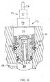
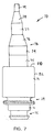
- the ground ring 74 is connected internally to the signal conditioning circuit (not shown) contained within the sensor portion 72 of the sensor 70.
- a first tapered portion 76 of insulated material extends axially from the ground ring to a second ring 77 formed from an electrically conductive material.
- the second ring 77 is connected internally to the signal conditioning circuit and thus provides an output signal connection.
- a second tapered portion 78 extends axially from the second ring 77 to a cylindrical tip 79 formed from electrically conducting material. The tip 79 extends through the connector 73 and provides a connection between a power supply and the signal conditioning circuit.
- a ground flange 80 is mounted upon the upper surface of the sensor portion 72.
- the sensor portion 72 includes a cylindrical metal housing 82 which has an upper end crimped onto the ground flange 80.
- the ground flange 80 is capacitively coupled (not shown) to the ground ring 74 to provide a ground for the sensor housing 82, while the coupling capacitor blocks noise from the signal conditioning circuit ground. Because the rings 74 and 77 extend completely around the connector 73, the orientation of the sensor 70 in the valve block is not important.
- the connector 73 is received by a corresponding female connector (not shown) having three electrical connectors.
- the female connector is mounted upon the electronic control module.
- the tapered portions 76 and 78 help guide the female connector over the male connector 73 when the electronic control module housing is assembled onto the valve body.
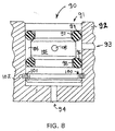
- Fig. 8 illustrates another embodiment 90 of the pressure sensor.
- the sensor 90 is shown disposed in a bore 91 formed in a hydraulic valve body 92.
- a cross bore 93 provides communication between the bore 92 and the vehicle master cylinder (not shown).
- An axial bore 94 provides a vent for the lower end of the bore 91.
- the pressure sensor includes first and second O-rings, 95 and 96, respectfully, which are disposed in first and second circumferential grooves 97 and 98.
- a third circumferential groove 100 is formed in the lower end of the sensor 90.
- a retaining spring ring 101 is disposed in the third groove 100 and cooperates with a corresponding groove 102 formed in the wall of the bore 91 to retain the pressure sensor 90 within the bore 91.
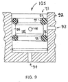
- FIG. 9 An alternate embodiment 105 of the pressure sensor 90 shown in Fig. 8 is illustrated in Fig. 9. Components shown in Fig. 9 which are similar to components in Fig. 8 have the same numerical designators. As described above, the axial forces exerted upon the sensor 105 are balanced. Therefore, the pressure sensor 105 does not include a spring retaining ring and the corresponding grooves to retain the sensor 105 within the bore 91 are not needed. Accordingly, the sensor 105 has a simpler structure and is less costly to manufacture that the sensor 90 described above.
- the signal conditioning circuit 23 can include an Application Specific Integrated Circuit (ASIC) which would provide a serial number output.
- ASIC Application Specific Integrated Circuit
- the electrical connector would include a bi-directional output pin.
- the serial output would be requested by the electronic control unit microprocessor.
- the electronic control unit microprocessor also could provide continuous monitoring of the sensor for faults such as bridge stray resistance, bridge open circuited, bridge short circuited, and/or ASIC failure. Upon power up, the ASIC could also perform a self test to assure that the pressure sensor is operational. Should the sensor be non-operational, the ASIC would generate an error signal which would be transmitted to the microprocessor in the electronic control module.
- the microprocessor would be responsive to the error signal to disable the ABS and provide a warning signal to the vehicle operator, such as illuminating a warning light.
Landscapes
- Physics & Mathematics (AREA)
- General Physics & Mathematics (AREA)
- Engineering & Computer Science (AREA)
- Fluid Mechanics (AREA)
- Mechanical Engineering (AREA)
- General Engineering & Computer Science (AREA)
- Electromagnetism (AREA)
- Chemical & Material Sciences (AREA)
- Analytical Chemistry (AREA)
- Transportation (AREA)
- Regulating Braking Force (AREA)
- Snaps, Bayonet Connections, Set Pins, And Snap Rings (AREA)
Applications Claiming Priority (6)
| Application Number | Priority Date | Filing Date | Title |
|---|---|---|---|
| US11398498P | 1998-12-28 | 1998-12-28 | |
| US113984P | 1998-12-28 | ||
| US11534199P | 1999-01-11 | 1999-01-11 | |
| US115341P | 1999-01-11 | ||
| DE19916087A DE19916087A1 (de) | 1999-04-09 | 1999-04-09 | Anordnung zur Messung eines Fluiddrucks |
| DE19916087 | 1999-04-09 |
Publications (3)
| Publication Number | Publication Date |
|---|---|
| EP1016573A2 true EP1016573A2 (de) | 2000-07-05 |
| EP1016573A3 EP1016573A3 (de) | 2000-10-18 |
| EP1016573B1 EP1016573B1 (de) | 2006-11-02 |
Family
ID=27219077
Family Applications (1)
| Application Number | Title | Priority Date | Filing Date |
|---|---|---|---|
| EP99126060A Expired - Lifetime EP1016573B1 (de) | 1998-12-28 | 1999-12-28 | Pressure sensor for a hydraulic control system and method for installing the sensor |
Country Status (1)
| Country | Link |
|---|---|
| EP (1) | EP1016573B1 (de) |
Cited By (8)
| Publication number | Priority date | Publication date | Assignee | Title |
|---|---|---|---|---|
| WO2000061414A1 (de) * | 1999-04-09 | 2000-10-19 | Lucas Industries Public Limited Company | Anordnung zur messung eines fluiddrucks |
| WO2003064230A1 (en) * | 2002-01-31 | 2003-08-07 | Kelsey-Hayes Company | Pressure sensor integrated into an electro-hydraulic control unit |
| WO2004001362A1 (de) * | 2002-06-22 | 2003-12-31 | Robert Bosch Gmbh | Einfaches hochdruck-sensor-gehaeuse durch verbindungsteil (auch emv) |
| US7011380B2 (en) * | 2001-08-13 | 2006-03-14 | Continental Teves Ag & Co. Ohg | Electrohydraulic pressure regulating device |
| CN108412922A (zh) * | 2018-05-07 | 2018-08-17 | 西安航空制动科技有限公司 | 一种飞机液压刹车系统压力调节器 |
| WO2019030121A1 (de) * | 2017-08-09 | 2019-02-14 | Ifm Electronic Gmbh | Messgerät zur messung des drucks eines mediums in einem behältnis und kapazitive druckmesszelle |
| CN111406243A (zh) * | 2017-11-30 | 2020-07-10 | 株式会社富士金 | 流量控制装置 |
| CN114935368A (zh) * | 2022-06-10 | 2022-08-23 | 陕西秦北检验检测有限公司 | 一种储罐附件压力流量检测装置 |
Family Cites Families (13)
| Publication number | Priority date | Publication date | Assignee | Title |
|---|---|---|---|---|
| US2935292A (en) * | 1957-11-07 | 1960-05-03 | Floyd M Williamson | Gauge retainers |
| ATE55467T1 (de) * | 1986-02-17 | 1990-08-15 | Hydrotechnik Gmbh | Fluidisches system mit messvorrichtung. |
| WO1988003491A1 (fr) * | 1986-11-14 | 1988-05-19 | Alfred Teves Gmbh | Dispositif electrohydraulique de controle continu de la pression de systemes hydrauliques de freinage de vehicules a moteur |
| FI81911C (fi) * | 1987-12-07 | 1990-12-10 | Vaisala Oy | Trycksaendare. |
| DE4121278A1 (de) * | 1991-06-27 | 1993-01-07 | Bosch Gmbh Robert | Hydraulische bremsanlage mit blockierschutzeinrichtung, insbesondere fuer kraftfahrzeuge |
| DE4211307A1 (de) * | 1992-04-04 | 1993-10-07 | Teves Gmbh Alfred | Elektromagnetventil, insbesondere für hydraulische Bremsanlagen mit Schlupfregelung |
| US5402824A (en) * | 1992-04-24 | 1995-04-04 | Nisshinbo Industries Inc. | Solenoid valve |
| US5343757A (en) * | 1992-05-21 | 1994-09-06 | Fuji Koki Manufacturing Co., Ltd. | Pressure sensor |
| DE19514383A1 (de) * | 1995-04-19 | 1996-10-24 | Teves Gmbh Alfred | Hydraulische Kraftfahrzeugbremsanlage mit Bremsschlupfregelung und/oder automatischem Bremseneingriff zur Antriebs- und/oder Fahrdynamikregelung |
| DE19545091B4 (de) * | 1995-12-04 | 2007-08-02 | Hydrostar Dipl.-Ing. Rolf Oehler Verwaltungs- und Beteiligungs-GmbH & Co. KG | Meßgerät mit einem Druckaufnehmer |
| DE19616658B4 (de) * | 1996-03-18 | 2009-11-19 | Ifm Electronic Gmbh | Meßgerät, z. B. Druckmeßgerät oder Strömungsmeßgerät |
| FR2750652B1 (fr) * | 1996-07-04 | 1998-11-13 | Peugeot | Systeme de commande d'une suspension hydropneumatique de vehicule automobile |
| US6312061B1 (en) * | 1998-11-25 | 2001-11-06 | Kelsey-Hayes Company | Structure for mounting a cluster of pressure sensors upon an electro-hydraulic brake system control unit |
-
1999
- 1999-12-28 EP EP99126060A patent/EP1016573B1/de not_active Expired - Lifetime
Cited By (12)
| Publication number | Priority date | Publication date | Assignee | Title |
|---|---|---|---|---|
| WO2000061414A1 (de) * | 1999-04-09 | 2000-10-19 | Lucas Industries Public Limited Company | Anordnung zur messung eines fluiddrucks |
| US6722204B2 (en) | 1999-04-09 | 2004-04-20 | Lucas Industries Plc | Balanced fluid pressure sensor |
| US7011380B2 (en) * | 2001-08-13 | 2006-03-14 | Continental Teves Ag & Co. Ohg | Electrohydraulic pressure regulating device |
| WO2003064230A1 (en) * | 2002-01-31 | 2003-08-07 | Kelsey-Hayes Company | Pressure sensor integrated into an electro-hydraulic control unit |
| WO2004001362A1 (de) * | 2002-06-22 | 2003-12-31 | Robert Bosch Gmbh | Einfaches hochdruck-sensor-gehaeuse durch verbindungsteil (auch emv) |
| US7363819B2 (en) | 2002-06-22 | 2008-04-29 | Robert Bosch Gmbh | High-pressure sensor housing which is simplified by means of a connection element (also emc) |
| WO2019030121A1 (de) * | 2017-08-09 | 2019-02-14 | Ifm Electronic Gmbh | Messgerät zur messung des drucks eines mediums in einem behältnis und kapazitive druckmesszelle |
| CN111406243A (zh) * | 2017-11-30 | 2020-07-10 | 株式会社富士金 | 流量控制装置 |
| CN108412922A (zh) * | 2018-05-07 | 2018-08-17 | 西安航空制动科技有限公司 | 一种飞机液压刹车系统压力调节器 |
| CN108412922B (zh) * | 2018-05-07 | 2019-11-15 | 西安航空制动科技有限公司 | 一种飞机液压刹车系统压力调节器 |
| CN114935368A (zh) * | 2022-06-10 | 2022-08-23 | 陕西秦北检验检测有限公司 | 一种储罐附件压力流量检测装置 |
| CN114935368B (zh) * | 2022-06-10 | 2024-05-28 | 陕西秦北检验检测有限公司 | 一种储罐附件压力流量检测装置 |
Also Published As
| Publication number | Publication date |
|---|---|
| EP1016573B1 (de) | 2006-11-02 |
| EP1016573A3 (de) | 2000-10-18 |
Similar Documents
| Publication | Publication Date | Title |
|---|---|---|
| US6374679B1 (en) | Pressure sensor integrated into an electro-hydraulic control unit | |
| US6506069B2 (en) | Floating electrical connector for a pressure sensor | |
| US6591684B2 (en) | Pressure sensor intergrated into an electro-hydraulic control unit | |
| US6007162A (en) | Hydraulic motor-vehicle brake system with anti-locking control and automatic actuation of the brakes for the control of the drive and/or travel dynamics | |
| EP1377469B1 (de) | Kombination aus einem automatischen reifenaufblassystem und einem antiblockierbremssystem | |
| US20040015282A1 (en) | High reliability pressure sensor | |
| EP1016573B1 (de) | Pressure sensor for a hydraulic control system and method for installing the sensor | |
| US6347845B1 (en) | Brake system for vehicles | |
| US6443536B1 (en) | Brake pressure modulator with pressure sensor manifold | |
| CN1326717C (zh) | 轮胎爆裂探测器 | |
| US5445448A (en) | Electromagnetically actuatable valve | |
| JP4440634B2 (ja) | 車両ブレーキ装置のブレーキ真空倍力装置とこのブレーキ真空倍力装置を備えた車両ブレーキ装置を運転する方法 | |
| US6220101B1 (en) | Apparatus for measuring multiple pressures | |
| US11904823B2 (en) | Hydraulic block for a hydraulic power unit of a hydraulic power vehicle braking system | |
| US4937553A (en) | Electrohydraulic device for continuously monitoring the pressure in a hydraulic brake system for automotive vehicles | |
| US6494101B2 (en) | Measuring device for brake system of motor vehicle | |
| JP2000009575A (ja) | 圧力測定のための装置 | |
| US7357466B2 (en) | Braking force generator for a hydraulic vehicle brake system | |
| DE10329489B4 (de) | Drucksteuergerät | |
| KR20210048778A (ko) | 브레이크 페달의 변위 감지장치 | |
| US20030205127A1 (en) | Sensor system for a vacuum brake booster | |
| US5195419A (en) | Method for assembling a piston-and-cylinder unit and force transmission element | |
| US6622077B2 (en) | Anti-lock braking system and method | |
| US12344213B2 (en) | Brake pressure sensor | |
| JP3154264B2 (ja) | 差圧センサ |
Legal Events
| Date | Code | Title | Description |
|---|---|---|---|
| PUAI | Public reference made under article 153(3) epc to a published international application that has entered the european phase |
Free format text: ORIGINAL CODE: 0009012 |
|
| AK | Designated contracting states |
Kind code of ref document: A2 Designated state(s): DE ES FR GB IT |
|
| AX | Request for extension of the european patent |
Free format text: AL;LT;LV;MK;RO;SI |
|
| PUAL | Search report despatched |
Free format text: ORIGINAL CODE: 0009013 |
|
| AK | Designated contracting states |
Kind code of ref document: A3 Designated state(s): AT BE CH CY DE DK ES FI FR GB GR IE IT LI LU MC NL PT SE |
|
| AX | Request for extension of the european patent |
Free format text: AL;LT;LV;MK;RO;SI |
|
| 17P | Request for examination filed |
Effective date: 20000926 |
|
| AKX | Designation fees paid |
Free format text: DE ES FR GB IT |
|
| 17Q | First examination report despatched |
Effective date: 20050617 |
|
| GRAP | Despatch of communication of intention to grant a patent |
Free format text: ORIGINAL CODE: EPIDOSNIGR1 |
|
| RTI1 | Title (correction) |
Free format text: DRUCKSENSOR FUER EIN HYDRAULISCHES STEUERSYSTEM UND MONTAGEVERFAHREN FUER DEN SENSOR |
|
| GRAS | Grant fee paid |
Free format text: ORIGINAL CODE: EPIDOSNIGR3 |
|
| GRAA | (expected) grant |
Free format text: ORIGINAL CODE: 0009210 |
|
| AK | Designated contracting states |
Kind code of ref document: B1 Designated state(s): DE ES FR GB IT |
|
| PG25 | Lapsed in a contracting state [announced via postgrant information from national office to epo] |
Ref country code: IT Free format text: LAPSE BECAUSE OF FAILURE TO SUBMIT A TRANSLATION OF THE DESCRIPTION OR TO PAY THE FEE WITHIN THE PRESCRIBED TIME-LIMIT;WARNING: LAPSES OF ITALIAN PATENTS WITH EFFECTIVE DATE BEFORE 2007 MAY HAVE OCCURRED AT ANY TIME BEFORE 2007. THE CORRECT EFFECTIVE DATE MAY BE DIFFERENT FROM THE ONE RECORDED. Effective date: 20061102 |
|
| REG | Reference to a national code |
Ref country code: GB Ref legal event code: FG4D |
|
| REF | Corresponds to: |
Ref document number: 69933846 Country of ref document: DE Date of ref document: 20061214 Kind code of ref document: P |
|
| PG25 | Lapsed in a contracting state [announced via postgrant information from national office to epo] |
Ref country code: ES Free format text: LAPSE BECAUSE OF FAILURE TO SUBMIT A TRANSLATION OF THE DESCRIPTION OR TO PAY THE FEE WITHIN THE PRESCRIBED TIME-LIMIT Effective date: 20070213 |
|
| EN | Fr: translation not filed | ||
| PLBE | No opposition filed within time limit |
Free format text: ORIGINAL CODE: 0009261 |
|
| STAA | Information on the status of an ep patent application or granted ep patent |
Free format text: STATUS: NO OPPOSITION FILED WITHIN TIME LIMIT |
|
| 26N | No opposition filed |
Effective date: 20070803 |
|
| GBPC | Gb: european patent ceased through non-payment of renewal fee |
Effective date: 20070202 |
|
| PG25 | Lapsed in a contracting state [announced via postgrant information from national office to epo] |
Ref country code: GB Free format text: LAPSE BECAUSE OF NON-PAYMENT OF DUE FEES Effective date: 20070202 Ref country code: FR Free format text: LAPSE BECAUSE OF FAILURE TO SUBMIT A TRANSLATION OF THE DESCRIPTION OR TO PAY THE FEE WITHIN THE PRESCRIBED TIME-LIMIT Effective date: 20070615 |
|
| PG25 | Lapsed in a contracting state [announced via postgrant information from national office to epo] |
Ref country code: FR Free format text: LAPSE BECAUSE OF FAILURE TO SUBMIT A TRANSLATION OF THE DESCRIPTION OR TO PAY THE FEE WITHIN THE PRESCRIBED TIME-LIMIT Effective date: 20061102 |
|
| PGFP | Annual fee paid to national office [announced via postgrant information from national office to epo] |
Ref country code: DE Payment date: 20181231 Year of fee payment: 20 |
|
| REG | Reference to a national code |
Ref country code: DE Ref legal event code: R071 Ref document number: 69933846 Country of ref document: DE |