EP1016599B1 - Doppelkammer-Filterbeutel für Aufgussprodukte und Verfahren zur Herstellung desselben - Google Patents
Doppelkammer-Filterbeutel für Aufgussprodukte und Verfahren zur Herstellung desselben Download PDFInfo
- Publication number
- EP1016599B1 EP1016599B1 EP99830793A EP99830793A EP1016599B1 EP 1016599 B1 EP1016599 B1 EP 1016599B1 EP 99830793 A EP99830793 A EP 99830793A EP 99830793 A EP99830793 A EP 99830793A EP 1016599 B1 EP1016599 B1 EP 1016599B1
- Authority
- EP
- European Patent Office
- Prior art keywords
- thread
- filter bag
- heat
- lobes
- bag
- Prior art date
- Legal status (The legal status is an assumption and is not a legal conclusion. Google has not performed a legal analysis and makes no representation as to the accuracy of the status listed.)
- Expired - Lifetime
Links
Images


Classifications
-
- B—PERFORMING OPERATIONS; TRANSPORTING
- B65—CONVEYING; PACKING; STORING; HANDLING THIN OR FILAMENTARY MATERIAL
- B65D—CONTAINERS FOR STORAGE OR TRANSPORT OF ARTICLES OR MATERIALS, e.g. BAGS, BARRELS, BOTTLES, BOXES, CANS, CARTONS, CRATES, DRUMS, JARS, TANKS, HOPPERS, FORWARDING CONTAINERS; ACCESSORIES, CLOSURES, OR FITTINGS THEREFOR; PACKAGING ELEMENTS; PACKAGES
- B65D85/00—Containers, packaging elements or packages, specially adapted for particular articles or materials
- B65D85/70—Containers, packaging elements or packages, specially adapted for particular articles or materials for materials not otherwise provided for
- B65D85/804—Disposable containers or packages with contents which are mixed, infused or dissolved in situ, i.e. without having been previously removed from the package
- B65D85/808—Disposable containers or packages with contents which are mixed, infused or dissolved in situ, i.e. without having been previously removed from the package for immersion in the liquid to release part or all of their contents, e.g. tea bags
- B65D85/812—Disposable containers or packages with contents which are mixed, infused or dissolved in situ, i.e. without having been previously removed from the package for immersion in the liquid to release part or all of their contents, e.g. tea bags with features facilitating their manipulation or suspension
-
- B—PERFORMING OPERATIONS; TRANSPORTING
- B65—CONVEYING; PACKING; STORING; HANDLING THIN OR FILAMENTARY MATERIAL
- B65B—MACHINES, APPARATUS OR DEVICES FOR, OR METHODS OF, PACKAGING ARTICLES OR MATERIALS; UNPACKING
- B65B29/00—Packaging of materials presenting special problems
- B65B29/02—Packaging of substances, e.g. tea, which are intended to be infused in the package
- B65B29/04—Attaching, or forming and attaching, string handles or tags to tea bags
-
- B—PERFORMING OPERATIONS; TRANSPORTING
- B65—CONVEYING; PACKING; STORING; HANDLING THIN OR FILAMENTARY MATERIAL
- B65D—CONTAINERS FOR STORAGE OR TRANSPORT OF ARTICLES OR MATERIALS, e.g. BAGS, BARRELS, BOTTLES, BOXES, CANS, CARTONS, CRATES, DRUMS, JARS, TANKS, HOPPERS, FORWARDING CONTAINERS; ACCESSORIES, CLOSURES, OR FITTINGS THEREFOR; PACKAGING ELEMENTS; PACKAGES
- B65D85/00—Containers, packaging elements or packages, specially adapted for particular articles or materials
- B65D85/70—Containers, packaging elements or packages, specially adapted for particular articles or materials for materials not otherwise provided for
- B65D85/804—Disposable containers or packages with contents which are mixed, infused or dissolved in situ, i.e. without having been previously removed from the package
- B65D85/808—Disposable containers or packages with contents which are mixed, infused or dissolved in situ, i.e. without having been previously removed from the package for immersion in the liquid to release part or all of their contents, e.g. tea bags
Definitions
- the present invention relates to a two-lobed filter bag for products for infusion, such as tea, camomile and similar products and to a method for making such a bag.
- the two pockets of the bag are defined by a series of transversal seals, creating separate pockets or lobes, each with a base and free end.
- a continuously fed thread is then positioned centrally and longitudinally on the tubular web, labels already being attached to the thread, at regular intervals, by a blob of heat-sealable material.
- the filter bag comprises two chambers or lobes obtained from a pair of webs, fed one above the other, following the depositing of product doses, and heat-sealed at the edges, then folded one towards the other with the characteristic "W"-shaped fold.
- the thread to which the label is attached may be wound longitudinally around the filter bag with its ends heat-sealed to the relative surfaces, or may be positioned on a single surface of the filter bag and gathered there under the pick-up label, which also serves to hold the thread in place.
- WO-A-97/19005 illustrates an infusion packet according to the preamble of claim 1, which comprises a pair of sealed compartments (12a, 12b) containing infusion material and joined together at opposite ends of the packet.
- a drawstring (14) attached intermediate its length to a connecting region (8) between the two compartments at one said ends has pull portions extending between the compartments from said attachment and held movably at the opposite end of the packet, whereby said pull portions can be drawn apart to contract the packet.
- the fragility of the join may cause the thread to be detached from the filter bag during packaging and handing of the package - bag, as well as during preparation of the infusion or as it is removed from the container.
- the structure of the bag as it has been made until now is not ideal for fast handling both during packaging (on the machine) and during final use.
- the aim of the present invention is, therefore, to overcome the above-mentioned disadvantages by providing a two-lobed filter bag which is extremely simple to make, very practical to use and safe for making infusions, with a good appearance.
- the filter bag disclosed defined as being of the two-lobed type, is used for containing and using products for infusion, such as tea, camomile and similar products.
- Such a filter bag labelled as a whole with the numeral 1, comprises two pockets or lobes 2 and 3, made of filter paper, each holding a dose 4 of the product for infusion (the product is illustrated with a dashed line).
- the lobes 2 and 3 are positioned in such a way that one surface 2a and 3a of each is opposite and/or in contact with the other and they are joined together at one end 2b and 3b, defining the base 5 of the filter bag 1.
- One end 6a of a bag support thread 6 is attached to one lobe, in this case labelled 3, of the filter bag 1, defining a connection point A.
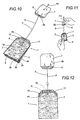
- the other end 6b of the thread 6 is attached to a pick-up label 7 for manipulating the filter bag 1 during infusion (clearly illustrated in Figure 12).
- the portion P of thread 6 between the two ends 6a and 6b is arranged in a packaging configuration, on the surfaces 2a and 3a of the lobes 2 and 3 which make contact with one another and on the base 5, that is to say, it is completely protected by the filter bag 1.
- end 6b of the thread 6 attached to the pick-up label 7 is attached to an additional end portion 8 of the free end 2c of the lobe 2 together with the pick-up element 7, again in a filter bag packaging configuration.
- the length S of the transversal heat-sealed zone 9, along the lobe 2 is preferably longer than the length S1 of the opposite heat-sealed zone 10.
- the additional end portion 8 is defined and delimited by a transversal weakening line L made in the heat-sealed zone 9 of the corresponding lobe 2.
- this weakness L allows the additional end portion 8 to be folded, in the packaging configuration and together with the end 6b of the thread 6, towards the outer surface 3d of the lobe 3 (wrapping around the upper part of the filter bag, see also arrow F1 in Figure 3a).
- the pick-up label 7 is positioned on said surface in such a way that it occupies the minimum amount of space possible.
- the weakness L allows detachment of the additional end portion 8, together with the end 6b of the thread 6 attached to the end portion and the pick-up label 7, so that during use of the bag 1, it allows the portion P of thread 6 to exit the bag as the pick-up label 7 is moved away from the bag 1 (see Figures 7 to 12).
- the loop of the section P1 of thread has the shape of a "U" lying on its side and is positioned completely within the heat-sealed zone 10.
- the structure of the filter bag 1 is completed by the fact that along a zone coinciding with the heat-sealed zones 9 and 10, the free ends 2c and 3c of the lobes 2 and 3, attached to one another in a packaging configuration, have corners 11 and 12 which are symmetrically tapered, relative to the ends, at an angle ⁇ .
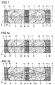
- FIGS. 1b and 1c show how the thread 6 may be deposited on the web in two different configurations on the tubular section of filter paper which will be used to form the bag disclosed.
- the thread 6 is positioned with a surplus portion 6pm, designed to increase the length of the portion P of thread present in the bag 1.
- the portion 6pm is placed on a central sealed section 13 which separates the two lobes 2 and 3.
- the central portion 6pm is substantially another additional section of thread 6, positioned transversally to the longitudinal axis X of the tubular section of filter paper, that is to say, parallel with the central seal 13 defined, for example, by "weak" heat-sealing points T1 and T2 designed to allow the subsequent detachment of the portion 6pm of thread as the thread exits the bag 1.
- the surplus portion 6pm is housed on the base 5 of the bag 1.
- the surplus portion 6pm is arranged in a zigzag pattern (to further increase the length of the portion P of thread 6) defined, for example, by another configuration of weak heat-sealed points labelled T3, T4, T5 and T6.
- This configuration allows the portion 6pm to occupy the minimum amount of space in the bag 1 packaging configuration, and allows the ends 6a and 6b of the thread 6 to be held along the above-mentioned longitudinal axis X.
- a filter bag 1 thus composed is made according to a succession of stages comprising: placing doses 4 of the product for infusion at equal distances from one another on a web of heat-sealable filter paper; folding the web along a longitudinal axis X; longitudinal LS and transversal heat-sealing of the web in such a way as to define a continuous tubular web which is closed and divided into individual portions, defining the lobes 2 and 3, at equal distances from one another (see Figure 1).
- the pairs of portions or lobes 2 and 3 then define the individual filter bag 1 delimited by two different transversal half seals 9 and 10, constituting the respective free ends 2c and 3c of the filter bag, and a complete intermediate seal 13 between the first two 9 and 10, designed to define the base 5 of the filter bag 1.
- the length S of the seal 9 is greater than that of the seal 10, to allow the subsequent definition of the additional end portion 8.
- the thread 6 is placed on the web, which is still continuous, in one of the above-mentioned configurations (see Figures 1a, 1b and 1c), with at least one section P1, coinciding with one end 6a of the thread, defining a loop and positioned on the transversal seal 10 opposite the end 2c on which the other end 6b of the thread 6 is placed.
- the thread positioning stage is followed by a stage in which the ends 6a and 6b of the thread 6 are heat-sealed to the transversal seals 9 and 10.
- the end 6b of the thread 6 positioned on the end 2c is sealed only along a section equal to the length of the additional end portion 8.
- the sealing stage is followed by a stage in which the web is cut, at the end transversal seals, defining the two halves 9 and 10, to obtain an individual filter bag 1 (this configuration is clearly illustrated in Figures 1, 1a, 1b and 1c).
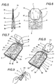
- the lobes 2 and 3 are folded towards one another and the seal 13 is folded into a "W" shape, defining the base 5 of the filter bag 1 and positioning the portion P of thread 6 between the two ends 6a and 6b on the surfaces 2a and 3a of the lobes 2 and 3 in contact with the base 5 (see Figure 2 and the arrows F).
- This folding allows the consequent attachment of the free ends 2c and 3c of the lobes 2 and 3, by another heat-sealing operation, keeping the additional end portion 8 outside the dimensions of the filter bag 1 thus obtained (see Figure 2a).
- the heat-sealing stage is followed by a stage for definition of the additional end portion 8 on the transversal seal (which will become the half 9 and, consequently, the end 2c of the bag 1), by means of a transversal weakening line L (see Figure 2b).
- the pick-up label 7 is attached to the additional end portion 8 and the side of the lobe 2 coinciding with the length of the portion 8, by another heat-sealing operation on the latter (see Figure 3).
- the end portion 8 is then folded, together with the end 6b of the thread 6 attached to it, towards the outer surface 3d of the lobe 3 (see Figure 3a and arrow F1) to "close" the zone at which the original ends 2c and 3c of the bag 1 are connected.
- the final stage in the manufacture of the filter bag 1 envisages cutting of the free ends 2c and 3c of the lobes 2 and 3 and the additional end portion 8, symmetrically relative to the ends, and where the corners 11 and 12 thus defined are tapered at an angle ⁇ (see Figures 4, 5 and 6).
- a first half 9 is preferably made, with the length S of the seal greater than the length S1 of the other half of the seal 10, so as to define an excess portion coinciding with the additional end portion 8. This simplifies the operations for folding the lobes 2 and 3 relative to the transversal centre line of the central seal 13.
- a filter bag 1 made in this way is prepared for infusion by the user as follows: gripping and rotating the pick-up label 7 away from the surface 3d (see arrow F2 in Figure 7); detaching the pick-up label 7, together with the additional end portion 8 and the end 6b of the thread 6 from the joined free ends 2c and 3c of the filter bag 1 (see arrow F3 in Figures 8 and 9) then pulling the pick-up label 7 away from the filter bag 1 (see arrow F4 in Figures 10 and 11) consequently pulling the portion P of thread out of the bag (see also Figure 12).
- the filter bag fulfils the stated aims thanks to the special configuration of the thread, protected between the two lobes and attached to the bag in a zone which is protected by the lobes and with a looped configuration which strengthens the connection between the thread and the bag.
- the end at which the thread and pick-up label are attached is further strengthened by the reciprocal fixing and, at the same time, protected by the additional end portion which is detached, for the bag infusion stage, together with the end of the thread and the pick-up label.
Landscapes
- Engineering & Computer Science (AREA)
- Mechanical Engineering (AREA)
- Packages (AREA)
- Infusion, Injection, And Reservoir Apparatuses (AREA)
- External Artificial Organs (AREA)
Claims (19)
- Doppelkammer-Filterbeutel für Aufgussprodukte, wie Tee, Kamillentee und ähnliche Substanzen, wobei der Filterbeutel (1) vom Typ mit zwei Säckchen (2, 3) aus Filterpapier ist, jede enthaltend eine Dosis (4) eines Aufgussproduktes; wobei die Säckchen (2, 3) auf solche Weise positioniert sind, dass eine Oberfläche (2a, 3a) eines jeden der anderen gegenüberliegt und/oder mit dieser im Kontakt angeordnet ist, und diese an einem, den Boden (5) des Filterbeutels (1) bildenden Ende (2b, 3b) miteinander verbunden sind; wobei ein Ende (6a) von einem Haltefaden (6) des Beutels an wenigstens einem Säckchen (2, 3) des Filterbeutels (1) befestigt ist und einen Verbindungspunkt (A) beschreibt, während das andere Ende (6b) des Fadens (6) an einem Anhänger (7) zum Aufnehmen des Filterbeutels (1) beim Aufgiessen befestigt ist, wobei das Ende (6a) des Fadens (6), welches den Verbindungspunkt (A) mit dem Filterbeutel (1) beschreibt, an dem freien Ende (3c) von dem genannten wenigstens einen Säckchen (3) und das andere Ende (6b) des Fadens, angebracht an dem Anhänger (7), an dem freien Ende (2c) des anderen Säckchens (2) befestigt ist, so dass in einer verpackten Darstellung der Abschnitt (P) des Fadens (6) zwischen den beiden Enden (6a, 6b) an den Oberflächen (2a, 3a) der Säckchen (2, 3), welche sich im Kontakt miteinander befinden, und/oder an dem Boden (5) liegt, dadurch gekennzeichnet, dass das an dem Anhänger (7) befestigte Ende (6b) des Fadens (6) an einem zusätzlichen Endabschnitt (8) des freien Endes (2c) des anderen Säckchens (2) zusammen mit dem Anhänger (7) angebracht ist.
- Filterbeutel nach Patentanspruch 1, dadurch gekennzeichnet, dass der zusätzliche Endabschnitt (8) durch eine querverlaufende, an dem Säckchen (2) angebrachte Abschwächungslinie (L) beschrieben ist, dazu bestimmt, das Lösen des Abschnittes zusammen mit dem Ende (6b) des Fadens (6) und dem Anhänger (7) zu erlauben, so dass während der Benutzung des Beutels (1) der Abschnitt (P) des Fadens (6) aus dem Beutel heraus kommt, wenn der Anhänger (7) von dem Beutel (1) entfernt wird.
- Filterbeutel nach Patentanspruch 1, dadurch gekennzeichnet, dass das den Verbindungspunkt (A) mit dem Beutel (1) beschreibende Ende (6a) des Fadens (6) aus einem Abschnitt (P1) des Fadens (6) besteht, angebracht an dem Ende (3c) des Säckchens (3) und eine Schlaufe beschreibend, das heisst ein stabile, ausgedehnte Kontaktfläche zwischen dem Faden (6) und dem Säckchen (3).
- Filterbeutel nach Patentanspruch 3, dadurch gekennzeichnet, dass die Schlaufe in dem Abschnitt (P1) des Fadens die Form eines auf seiner Seite liegenden "U" hat.
- Filterbeutel nach einem beliebigen der vorstehenden Patentansprüche, bei welchem die Säckchen (2, 3) einen heissversiegelten Bereich oder Abschnitt (9, 10) haben, welcher das entsprechende freie Ende (2c, 3c) verschliesst, wobei der Filterbeutel dadurch gekennzeichnet ist, dass die Enden (6a, 6b) des Fadens (6) an den freien Enden (3c, 2c) der Säckchen (3, 2) an den heissversiegelten Bereichen (10, 9) befestigt sind, von welchen einer den zusätzlichen Endabschnitt (8) des Säckchens (2) enthält, an dem ein Ende (6b) des Fadens befestigt ist; wobei beide Enden (6a, 6b) entlang einer längsverlaufenden Achse (X) des Filterbeutels (1) angeordnet sind.
- Filterbeutel nach den Patentansprüchen 1 und 5, dadurch gekennzeichnet, dass die freien Enden (2c, 3c) der Säckchen (2, 3), die miteinander verbunden sind, in einer verpackten Darstellung entlang einem Bereich, der mit den heissversiegelten Bereichen (9, 10) übereinstimmt, Ecken (11, 12) aufweist, die im Verhältnis zu den Enden in einem vorgegebenen Winkel (α) symmetrisch abgeschrägt sind.
- Filterbeutel nach den Patentansprüchen von 1 bis 5, dadurch gekennzeichnet, dass der zusätzliche Endabschnitt (8) an dem Säckchen (2) durch einen querverlaufenden, heissversiegelten Bereich (9) beschrieben wird, dessen Abmessung (S) entlang dem Säckchen (2) grösser ist als die Abmessung (S1) des gegenüberliegenden heissversiegelten Bereiches (10), wobei der Abschnitt (8) durch eine, an dem heissversiegelten Bereich (9) hergestellte Abschwächungslinie (L) beschrieben wird.
- Filterbeutel nach den Patentansprüchen 1 und 2, dadurch gekennzeichnet, dass der zusätzliche Endabschnitt (8) in einer verpackten Darstellung zusammen mit dem Ende (6b) des Fadens (6) zu der äusseren Oberfläche (3d) des Säckchens (3) hin umgefaltet werden kann, was es dem Anhänger (7) erlaubt, an der genannten Oberfläche positioniert zu werden und die freien Enden (2c, 3c) zu "verschliessen".
- Filterbeutel nach Patentanspruch 1, dadurch gekennzeichnet, dass der Abschnitt (P) des Fadens (6) zwischen den Enden (6a, 6b) eine Zusatzlänge (6pm) enthält, dazu bestimmt, die Länge des Abschnittes (P) des Fadens (6) für den Aufguss zu verlängern.
- Filterbeutel nach Patentanspruch 9, dadurch gekennzeichnet, dass in einer verpackten Darstellung die Zusatzlänge (6pm) am Boden (5) des Filterbeutels (1) angeordnet ist.
- Filterbeutel nach den Patentansprüchen 9 und 10, dadurch gekennzeichnet, dass die Zusatzlänge (6pm) des Fadens (6) aus einem anderen zusätzlichen Abschnitt des Fadens (6) besteht, der sich in zickzackförmig erstreckt, bestimmt durch eine Anzahl von "schwachen" Heissversiegelungspunkten (T1, T2; T3, T4, T5, T6), die dazu dienen, dass anschliessende Lösen der Zusatzlänge (6pm) des Fadens (6) zu erlauben, wenn der Faden (6) aus dem Beutel (1) heraus kommt.
- Verfahren zur Herstellung eines Filterbeutels nach Patentanspruch 1, wobei das Verfahren wenigstens die folgenden Phasen enthält:wobei das Verfahren dadurch gekennzeichnet ist, dass es die folgenden Phasen enthält:Anordnen der Dosen (4) des Aufgussproduktes in gleichmässigen Abständen voneinander auf der Bahn aus heissversiegelbarem Filterpapier;Umfalten der Bahn entlang einer Längsachse (X);Heissversiegeln der Bahn in Längsrichtung (LS) und Querrichtung (9, 10, 13), um eine kontinuierliche, schlauchförmige Bahn zu bilden, die geschlossen und in einzelne Abschnitte unterteilt ist, welche in einem gleichen Abstand voneinander die Säckchen (2, 3) bilden, wobei die aufeinanderfolgenden Paare von Säckchen jeweils einen einzelnen Filterbeutel (1) beschreiben, die durch zwei querverlaufende Siegelnähte abgegrenzt sind, wobei die entsprechenden Hälften (9, 10) die freien Enden (2c, 3c) des Filterbeutels bilden und eine vollständige Siegelnaht (13) zwischen den ersten beiden (9, 10) dazu bestimmt ist, den Boden (5) des Filterbeutels (1) zu beschreiben;Anordnen eines kontinuierlichen Fadens (6) an der schlauchförmigen Bahn (N), wobei der Faden wenigstens einen Abschnitt (P1) hat, der mit einem seiner Enden (6a) übereinstimmt, das an der querverlaufenden Siegelnaht (10) entgegengesetzt zu dem Ende (2c) des Beutels angeordnet ist, an welcher sich das andere Ende (6b) des Fadens (6) befindet; wobei beide Enden (6a, 6b) des Fadens entlang einer Längsachse (X) angeordnet sind;Heissversiegeln wenigstens der Enden (6a, 6b) des Fadens (6) an den querverlaufenden Siegelnähten (10, 9);Zerschneiden der Bahn (N) an den Siegelnähten am Ende, welche die Hälften (9, 10) bilden, um die einzelnen Filterbeutel (1) zu erhalten;Umfalten der Säckchen (2, 3) eins zum anderen hin, so dass der Abschnitt (P) zwischen den beiden Enden (6a, 6b) des Fadens an den Oberflächen (2a, 3a) der Säckchen (2, 3) zu liegen kommt, die sich im Kontakt miteinander befinden, und anschliessendes Verbinden der freien Enden (2c, 3c) der Säckchen (2, 3) miteinander;Bilden eines zusätzlichen Endabschnittes (8), der sich aus der querverlaufenden Siegelnaht (9) ergibt;Anordnen des Endes (6b) des Fadens (6) an dem zusätzlichen Endabschnitt (8), welcher sich an dem Ende (2c) des Beutels befindet;Halten des zusätzlichen Endabschnittes (8) ausserhalb der Abmessungen des wie oben erhaltenen Filterbeutels (1);Anbringen des Anhängers (7) an dem zusätzlichen Endabschnitt (8);Umfalten des zusätzlichen Endabschnittes (8) zusammen mit dem an diesem befestigten Ende (6b) des Fadens (6) gegen die äussere Oberfläche (3d) des Säckchens (3).
- Verfahren nach Patentanspruch 12, dadurch gekennzeichnet, dass der Abschnitt (P1), der mit einem der Enden (6a) des Fadens (6) übereinstimmt, eine Schlaufe beschreibt, die an dem Ende (3c) des Beutels an der querverlaufenden Siegelnaht (10) angeordnet ist.
- Verfahren nach Patentanspruch 12, dadurch gekennzeichnet, dass in der Herstellungsphase der querverlaufenden Siegelnähte (9, 10) an der Bahn eine erste Hälfte der Siegelnaht (9) eine grössere Abmessung (S) aufweist als die Abmessung (S1) der anderen Hälfte der Siegelnaht (10), wobei ein überstehender und mit dem zusätzlichen Abschnitt (8) übereinstimmender Abschnitt gebildet wird.
- Verfahren nach Patentanspruch 12, dadurch gekennzeichnet, dass der Phase des Umfaltens eine Phase zum Bilden des Endabschnittes (8) durch eine querverlaufende Abschwächungslinie (L) vorausgeht, dazu bestimmt, den Endabschnitt (8) von der Hälfte (9) zu trennen.
- Verfahren nach Patentanspruch 12, dadurch gekennzeichnet, dass das Ende (6b) des Fadens (6), welches an dem Anhänger (7) befestigt werden kann, an der Bahn über eine Länge versiegelt wird, die der Länge (L) des zusätzlichen Endabschnittes (8) entspricht.
- Verfahren nach Patentanspruch 12, dadurch gekennzeichnet, dass der Phase des Anbringens des Anhängers (7) eine Phase des Schneidens der freien Enden (2c, 3c) der Säckchen (2, 3) und des zusätzlichen Endabschnittes (8) folgt, und zwar symmetrisch im Verhältnis zu den Enden, wobei die Ecken (11, 12) um einen Winkel (α) abgeschrägt sind.
- Verfahren nach Patentanspruch 12, dadurch gekennzeichnet, dass die Phase des Anbringens des Anhängers (7) durch Heissversiegeln ausgeführt wird.
- Verfahren nach Patentanspruch 12, dadurch gekennzeichnet, dass die Phase des Heissversiegelns der Enden (6a, 6b) des Fadens (6) das gleichzeitige schwache Heissversiegeln einer Zusatzlänge (6pm) des Fadens an der vollständigen mittleren Siegelnaht (13) vorsieht, wobei die genannte Zusatzlänge zickzackförmig angeordnet wird, bestimmt durch eine Anzahl von Heissversiegelungspunkten (T1, T2; T3, T4, T5, T6).
Applications Claiming Priority (2)
| Application Number | Priority Date | Filing Date | Title |
|---|---|---|---|
| IT1998BO000715A IT1304448B1 (it) | 1998-12-24 | 1998-12-24 | Sacchetto - filtro bilobo per prodotti da infusione. |
| ITBO980715 | 1998-12-24 |
Publications (2)
| Publication Number | Publication Date |
|---|---|
| EP1016599A1 EP1016599A1 (de) | 2000-07-05 |
| EP1016599B1 true EP1016599B1 (de) | 2003-07-23 |
Family
ID=11343583
Family Applications (1)
| Application Number | Title | Priority Date | Filing Date |
|---|---|---|---|
| EP99830793A Expired - Lifetime EP1016599B1 (de) | 1998-12-24 | 1999-12-22 | Doppelkammer-Filterbeutel für Aufgussprodukte und Verfahren zur Herstellung desselben |
Country Status (3)
| Country | Link |
|---|---|
| EP (1) | EP1016599B1 (de) |
| DE (1) | DE69909726T2 (de) |
| IT (1) | IT1304448B1 (de) |
Cited By (3)
| Publication number | Priority date | Publication date | Assignee | Title |
|---|---|---|---|---|
| USD779674S1 (en) | 2015-02-27 | 2017-02-21 | 3M Innovative Properties Company | Filter element having a connector |
| USD786443S1 (en) | 2015-02-27 | 2017-05-09 | 3M Innovative Properties Company | Filter element |
| USD792959S1 (en) | 2015-02-27 | 2017-07-25 | 3M Innovative Properties Company | Filter element having a pattern |
Families Citing this family (7)
| Publication number | Priority date | Publication date | Assignee | Title |
|---|---|---|---|---|
| ITBO20020013A1 (it) * | 2002-01-11 | 2003-07-11 | Tecnomeccanica Srl | Busta filtro per contenimento di una sostanza da infusione con accumulo di filo associato alla etichetta di presa e metodo di formatura rela |
| DE202005008832U1 (de) * | 2005-06-03 | 2006-10-12 | Teepack Spezialmaschinen Gmbh & Co. Kg | Aufgussbeutel |
| ITBO20060581A1 (it) * | 2006-07-31 | 2008-02-01 | Ima Spa | Bustina monolobo per prodotti da infusione. |
| ITBO20070408A1 (it) * | 2007-06-11 | 2008-12-12 | I M A Ind Macchine Automatic H | Bustina monolobo per prodotti da infusione. |
| KR101254937B1 (ko) * | 2011-12-05 | 2013-04-23 | 주식회사 티레모 | 스틱형 티백의 제조방법 |
| EP3261729B1 (de) | 2015-02-27 | 2019-08-28 | 3M Innovative Properties Company | Flexibles filterelement mit einem auslass |
| DE202019101345U1 (de) | 2019-03-08 | 2019-06-17 | Badusan Gmbh | Doppelkammer-Faltbeutel für verschiedene Füllmaterialien |
Family Cites Families (5)
| Publication number | Priority date | Publication date | Assignee | Title |
|---|---|---|---|---|
| CH587642A5 (de) * | 1975-03-25 | 1977-05-13 | Sig Schweiz Industrieges | |
| IT1187308B (it) * | 1985-02-08 | 1987-12-23 | Cestind Centro Studi Ind | Sacchetto-filtro biuso per prodotti da infusione e metodo per produrlo |
| EP0448325B1 (de) * | 1990-03-21 | 1993-08-11 | Unilever Plc | Beutel und Verpackungsverfahren |
| TR199800873T2 (xx) * | 1995-11-17 | 1998-08-21 | Unilever N.V. | Demleme po�eti ve bunun imalat�. |
| DE59604043D1 (de) * | 1996-05-07 | 2000-02-03 | Teepack Spezialmaschinen | Doppelkammer-Aufgussbeutel, insbesondere für Tee, und Verfahren zu seiner Herstellung |
-
1998
- 1998-12-24 IT IT1998BO000715A patent/IT1304448B1/it active
-
1999
- 1999-12-22 DE DE69909726T patent/DE69909726T2/de not_active Expired - Lifetime
- 1999-12-22 EP EP99830793A patent/EP1016599B1/de not_active Expired - Lifetime
Cited By (3)
| Publication number | Priority date | Publication date | Assignee | Title |
|---|---|---|---|---|
| USD779674S1 (en) | 2015-02-27 | 2017-02-21 | 3M Innovative Properties Company | Filter element having a connector |
| USD786443S1 (en) | 2015-02-27 | 2017-05-09 | 3M Innovative Properties Company | Filter element |
| USD792959S1 (en) | 2015-02-27 | 2017-07-25 | 3M Innovative Properties Company | Filter element having a pattern |
Also Published As
| Publication number | Publication date |
|---|---|
| ITBO980715A1 (it) | 2000-06-24 |
| IT1304448B1 (it) | 2001-03-19 |
| ITBO980715A0 (it) | 1998-12-24 |
| EP1016599A1 (de) | 2000-07-05 |
| DE69909726D1 (de) | 2003-08-28 |
| DE69909726T2 (de) | 2004-07-22 |
Similar Documents
| Publication | Publication Date | Title |
|---|---|---|
| AU651526B2 (en) | Infusion packets | |
| US4055668A (en) | Infusion package | |
| US4828851A (en) | Filter bag for infusible products | |
| US4730943A (en) | Plastic bag with carrying handle | |
| US3722377A (en) | Bags | |
| EP1016599A1 (de) | Doppelkammer-Filterbeutel für Aufgussprodukte und Verfahren zur Herstellung desselben | |
| US6733804B1 (en) | Multi-chambered infusion bag, especially for tea | |
| CN101687593B (zh) | 用于浸泡产品的单叶过滤袋 | |
| JPH0815895B2 (ja) | ふり出し用浸出製品を封入する両用フィルター袋のための連続自動生産装置 | |
| JP2017159960A (ja) | 袋体を形成する方法及び袋体 | |
| JP2702236B2 (ja) | タグ付き吊り紐を備えた煎じ出し用濾紙袋、その連続製造方法及び製造装置 | |
| GB2052428A (en) | Infusion bags | |
| US7021025B2 (en) | Filter bag for containing a substance for infusion with the gathered thread attached to the pick up tag and the method for producing the bag | |
| US6389781B1 (en) | Two-lobed filter bag for products for infusion | |
| US2987857A (en) | Method of producing infusion bags | |
| CA2237933C (en) | Infusion packet and its manufacture | |
| US2794745A (en) | Infusion bag | |
| WO1993015974A1 (en) | Infusion packages | |
| JP3801244B2 (ja) | 縦長型物品用手提げ袋及びその製造方法 | |
| JPH0630004U (ja) | 濾しパック | |
| AU3461093A (en) | Infusion packages | |
| JPH08281840A (ja) | 包装袋の製造方法及びその包装袋 |
Legal Events
| Date | Code | Title | Description |
|---|---|---|---|
| PUAI | Public reference made under article 153(3) epc to a published international application that has entered the european phase |
Free format text: ORIGINAL CODE: 0009012 |
|
| AK | Designated contracting states |
Kind code of ref document: A1 Designated state(s): DE FR GB IT |
|
| AX | Request for extension of the european patent |
Free format text: AL;LT;LV;MK;RO;SI |
|
| 17P | Request for examination filed |
Effective date: 20000720 |
|
| AKX | Designation fees paid |
Free format text: DE FR GB IT |
|
| 17Q | First examination report despatched |
Effective date: 20020313 |
|
| GRAH | Despatch of communication of intention to grant a patent |
Free format text: ORIGINAL CODE: EPIDOS IGRA |
|
| GRAH | Despatch of communication of intention to grant a patent |
Free format text: ORIGINAL CODE: EPIDOS IGRA |
|
| GRAA | (expected) grant |
Free format text: ORIGINAL CODE: 0009210 |
|
| AK | Designated contracting states |
Designated state(s): DE FR GB IT |
|
| PG25 | Lapsed in a contracting state [announced via postgrant information from national office to epo] |
Ref country code: FR Free format text: LAPSE BECAUSE OF FAILURE TO SUBMIT A TRANSLATION OF THE DESCRIPTION OR TO PAY THE FEE WITHIN THE PRESCRIBED TIME-LIMIT Effective date: 20030723 |
|
| REG | Reference to a national code |
Ref country code: GB Ref legal event code: FG4D |
|
| REF | Corresponds to: |
Ref document number: 69909726 Country of ref document: DE Date of ref document: 20030828 Kind code of ref document: P |
|
| PLBE | No opposition filed within time limit |
Free format text: ORIGINAL CODE: 0009261 |
|
| STAA | Information on the status of an ep patent application or granted ep patent |
Free format text: STATUS: NO OPPOSITION FILED WITHIN TIME LIMIT |
|
| 26N | No opposition filed |
Effective date: 20040426 |
|
| EN | Fr: translation not filed | ||
| REG | Reference to a national code |
Ref country code: GB Ref legal event code: 732E Free format text: REGISTERED BETWEEN 20091022 AND 20091028 |
|
| REG | Reference to a national code |
Ref country code: GB Ref legal event code: 732E Free format text: REGISTERED BETWEEN 20150226 AND 20150304 |
|
| PGFP | Annual fee paid to national office [announced via postgrant information from national office to epo] |
Ref country code: DE Payment date: 20161121 Year of fee payment: 18 Ref country code: GB Payment date: 20161128 Year of fee payment: 18 |
|
| PGFP | Annual fee paid to national office [announced via postgrant information from national office to epo] |
Ref country code: IT Payment date: 20161125 Year of fee payment: 18 |
|
| REG | Reference to a national code |
Ref country code: DE Ref legal event code: R119 Ref document number: 69909726 Country of ref document: DE |
|
| GBPC | Gb: european patent ceased through non-payment of renewal fee |
Effective date: 20171222 |
|
| PG25 | Lapsed in a contracting state [announced via postgrant information from national office to epo] |
Ref country code: DE Free format text: LAPSE BECAUSE OF NON-PAYMENT OF DUE FEES Effective date: 20180703 Ref country code: IT Free format text: LAPSE BECAUSE OF NON-PAYMENT OF DUE FEES Effective date: 20171222 |
|
| PG25 | Lapsed in a contracting state [announced via postgrant information from national office to epo] |
Ref country code: GB Free format text: LAPSE BECAUSE OF NON-PAYMENT OF DUE FEES Effective date: 20171222 |