EP1016737A1 - Cellule d'électrolyse pour la production de gaz - Google Patents
Cellule d'électrolyse pour la production de gaz Download PDFInfo
- Publication number
- EP1016737A1 EP1016737A1 EP99310527A EP99310527A EP1016737A1 EP 1016737 A1 EP1016737 A1 EP 1016737A1 EP 99310527 A EP99310527 A EP 99310527A EP 99310527 A EP99310527 A EP 99310527A EP 1016737 A1 EP1016737 A1 EP 1016737A1
- Authority
- EP
- European Patent Office
- Prior art keywords
- sealing element
- anode
- current collector
- collector plate
- cathode
- Prior art date
- Legal status (The legal status is an assumption and is not a legal conclusion. Google has not performed a legal analysis and makes no representation as to the accuracy of the status listed.)
- Granted
Links
Images







Classifications
-
- C—CHEMISTRY; METALLURGY
- C25—ELECTROLYTIC OR ELECTROPHORETIC PROCESSES; APPARATUS THEREFOR
- C25B—ELECTROLYTIC OR ELECTROPHORETIC PROCESSES FOR THE PRODUCTION OF COMPOUNDS OR NON-METALS; APPARATUS THEREFOR
- C25B1/00—Electrolytic production of inorganic compounds or non-metals
- C25B1/01—Products
- C25B1/13—Ozone
-
- C—CHEMISTRY; METALLURGY
- C25—ELECTROLYTIC OR ELECTROPHORETIC PROCESSES; APPARATUS THEREFOR
- C25B—ELECTROLYTIC OR ELECTROPHORETIC PROCESSES FOR THE PRODUCTION OF COMPOUNDS OR NON-METALS; APPARATUS THEREFOR
- C25B9/00—Cells or assemblies of cells; Constructional parts of cells; Assemblies of constructional parts, e.g. electrode-diaphragm assemblies; Process-related cell features
- C25B9/17—Cells comprising dimensionally-stable non-movable electrodes; Assemblies of constructional parts thereof
- C25B9/19—Cells comprising dimensionally-stable non-movable electrodes; Assemblies of constructional parts thereof with diaphragms
-
- Y—GENERAL TAGGING OF NEW TECHNOLOGICAL DEVELOPMENTS; GENERAL TAGGING OF CROSS-SECTIONAL TECHNOLOGIES SPANNING OVER SEVERAL SECTIONS OF THE IPC; TECHNICAL SUBJECTS COVERED BY FORMER USPC CROSS-REFERENCE ART COLLECTIONS [XRACs] AND DIGESTS
- Y02—TECHNOLOGIES OR APPLICATIONS FOR MITIGATION OR ADAPTATION AGAINST CLIMATE CHANGE
- Y02E—REDUCTION OF GREENHOUSE GAS [GHG] EMISSIONS, RELATED TO ENERGY GENERATION, TRANSMISSION OR DISTRIBUTION
- Y02E60/00—Enabling technologies; Technologies with a potential or indirect contribution to GHG emissions mitigation
- Y02E60/30—Hydrogen technology
- Y02E60/36—Hydrogen production from non-carbon containing sources, e.g. by water electrolysis
Definitions
- the invention relates to an aqueous electrolysis cell for generation of gas, wherein the cell is adapted to be easily attached to or detached from a facility which collects and uses the gas.
- the invention relates to an aqueous electrolysis cell which is assured both of sufficient anticorrosion characteristic and sufficient sealing characteristic against both of ozone gas and ozone aqueous solution, because ozone gas is generated in the cell.
- Electrolysis cells which generate ozone gas by electrolysis reaction of water are known.
- these known types of cells have a cathode chamber and an anode chamber which is separate from the cathode chamber by a cation-exchanger membrane made of, for example, solid electrolyte polymer.
- Hydrogen gas is generated in the cathode chamber.
- Mixed gas of ozone and oxygen is generated in the anode chamber.
- the electrodes in the cells are replaced at an interval of about one or two years, particularly if the cells are used to provide ozone gas to a facility which utilizes ozone gas.
- the facility has a container for separation of gas from liquid.
- the container communicates with the anode chamber directly or via an additional line.
- Such a container hereinafter referred to as a "anode trap" collects the ozone gas.
- the collected ozone gas is provided to the places to use it.
- Japanese Patent Laid-Open (Kokai) No. Hei 10-25586 teaches a structure assembly of an aqueous electrolysis cell which can generate ozone gas, oxygen gas and hydrogen gas.
- the structure is made of components which can be disassembled.
- most of the structure's clamping bolts which have maintained the structure should be loosen or disengaged, wherein many parts around the electrodes come apart totally. Therefore, in order to assemble the parts again, many positioning works have to be done again. It is a very large burden in the maintenance work.
- the object of the present invention is to provide an aqueous electrolysis cell, in which maintenance labors and costs are reduced as compared with conventional aqueous electrolysis cells, especially in the maintenance to replace its electrode portions.
- Another object of the invention is to provide an aqueous electrolysis cell which can be easily attached to and detached from a facility which collects and uses the gas.
- an aqueous electrolysis cell for generation of gas comprises an electrolysis container having an anode chamber and a cathode chamber separated from each other by a membrane, the cell being adapted to generate by electrolysis reaction of water oxygen and ozone in the anode chamber and hydrogen in the cathode chamber.
- the cell includes an anode having permeability to gas and water and fitted on the membrane in such a manner that one surface of the anode is in contact with one surface of the membrane.
- a cathode has permeability to gas and water and is fitted on the membrane in such a manner that one surface of the cathode is in contact with the other surface of the membrane.
- a first sealing element is fitted on the anode and the membrane to surround and seal circumference of the anode, one surface of the first sealing element being in tight contact with the one surface of the membrane, and the first sealing element has an opening communicating with the anode.
- An anode current collector plate has one surface in tight contact with the other surface of the first sealing element, and a through-hole communicating with the opening of the first sealing element.
- a second sealing element has one surface in tight contact with the other surface of the anode current collector plate, and an opening communicating with the through-hole of the anode current collector plate.
- a conduit is provided to connect the flow passage to a separator for collecting gas generated in the anode chamber.
- a flange is also provided and fastened to the conduit, the second sealing element, the anode current collector plate and the first sealing element for providing tight contact therebetween.
- the flange has means for fastening the conduit to the separator.
- a casing defines the anode chamber and the cathode chamber and has a bottom wall.
- each of the flange, the conduit, the second sealing element, the anode current collector plate and the first sealing element has a hole.
- a bolt fastens the flange to the conduit, the second sealing element, the anode current collector plate and the first sealing element through the holes.
- the means for fastening the conduit to the separator may be a hole provided in the flange.
- the cell further comprises a bolt extending through the hole for attaching the flange to the separator.
- the cell further comprises a third sealing element fitted on the cathode and the membrane to surround and seal circumference of the cathode, one surface of the third sealing element being in tight contact with the one surface of the membrane, and the third sealing element having an opening communicating with the cathode.
- a cathode current collector plate has one surface in tight contact with the other surface of the third sealing element, and a through-hole communicating with the opening of said third sealing element.
- a fourth sealing element has one surface in tight contact with the other surface of the cathode current collector plate, and an opening communicating with the through-hole of the cathode current collector plate. The bottom wall of the casing is in tight contact with the other surface of the fourth sealing element.
- Each of the third sealing element, the cathode current collector plate, the fourth sealing element and the casing has a hole.
- the bolt also fastens the flange to the third sealing element, the cathode current collector plate, the fourth sealing element and the casing through the holes.
- an aqueous electrolysis cell 100 for generating ozone gas is hereinafter explained.
- the side of the cell 100 in its usual orientation as shown in Figure 1 is indicated as the front, although the orientation or attitude of the cell 100 in which it can be operated is not always limited to a particular one, as will be mentioned later.
- the cell 100 has a generally cylindrical shape, showing its schematic front elevation in Figure 1.
- the cell 100 has an anode current collector plate 2 and a cathode current collector plate 3.
- the plate 2 is extending leftward from inside of the cell 100.
- the plate 3 is also extending leftward from inside of the cell 100.
- the plate 2 and plate 3 are spaced apart from each other and are connected to a proper power source (not shown in the figures).
- the cell 100 is provided with a pair of flanges 13, one of which extending upward and the other extending downward.
- An ozone user facility which can be supplied ozone gas and oxygen gas from anode chamber of the cell 100 would be, in many cases, provided with a container or something like that for the purpose of receiving aqueous solution that communicates with the anode chamber of the cell 100.
- the container constitutes a separation equipment for separation of gas from liquid.
- Each of the flanges 13 acts for attaching the cell 100 to this kind of container.
- each of the flanges 13 has a hole 22 for receiving a bolt.
- the cell 100 has a casing 8 which has an opening 191 to which a suitable pipeline 19 for letting out a mixed fluid of hydrogen gas and water is connected. Further, a reinforcement plate 14 is provided at front side of the casing 8. The reinforcement plate 14 has an opening 190 in alignment with the opening 191 of the casing 8. This alignment is for the purpose of letting the pipeline 19 extend though the opening 190.
- the casing 8 is partly visible through the opening 190.
- the cathode current collector plate 3 located inside is visible through the opening 191. From the outside of the reinforcement plate 14, eight bolts 12 are inserted into corresponding female threads formed in the flanges 13.
- the bolts are screwed so that the bolts and female threads are tightened against each other so as to keep the following components secured together tightly, i.e., the reinforcement plate 14, the casing 8, four sealing elements (which will be explained later), the cathode current collector plate 3, the anode current collector plate 2, and a tubular connection element 9 (which will be explained later), thus forming the cell 100.
- FIG 2 a plan view of the cell 100 is shown.
- An upper one of the aforementioned two flanges 13 that are fitted at the circumference of the tubular connection element 9 that can be connected to the aforementioned kind of container is indicated in the figure.
- An 0-ring 10 made of fluororesin that is fitted on the circumference of the tubular connection element 9 is also shown.
- Figure 3 is an elevational backside view of the cell 100.
- the anode current collector plate 2 is located at a position deeper than an opening of the tubular connection element 9.
- the plate 2 is partly visible through the opening.
- connection element 9 is extending radially outwardly at one end thereof, which is to be pushed against the pair of electrodes 7, thereby making a closed annular seal substantially impervious to both of gas and liquid, between the pair of electrodes 7 and the connection element 9.
- connection element 9 has a second radially outwardly extending portion which is to be used as an stopper for the O-ring 10 which is fitted on the circumference of the element 9.
- the electrodes portion 7 has an anode 4 and a cathode 5, wherein the anode 4 has a structure permeable to both of gas and water.
- the anode 4 is to be closely contacted against a backside surface of a cation-exchanger membrane 6.
- the cathode 5 also has a structure permeable to both of gas and water.
- the cathode 5 is to be closely contacted against front surface of the cation-exchanger membrane 6.
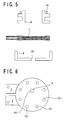
- a first generally flat and thin doughnut-like sealing element la which has a central opening is located, in tight contact with the aforementioned backside surface of the cation-exchanger membrane 6.
- a closed annular seal surrounding the periphery of the anode 4, surrounded by the periphery of the sealing element la is achieved.
- eight through holes are formed in substantially equally spaced apart positions, as a whole making a circle. Six of the eight holes are shown in Figure 9.
- the anode current collector plate 2 is located with one of its surfaces in tight contact with the backside surface of the first sealing element la.
- the plate 2 has a generally disc-shaped portion and eight through holes in the vicinity of the periphery of the disc-shaped portion.
- the eight through holes of the plate 2 are aligned with the aforementioned eight through holes of the first sealing element.
- a plurality of openings 102 are located on a hypothetical generally circular line. These plurality of openings 102 of the plate 2 communicate the central opening of the first sealing element la and further communicate the anode 4 via the central opening.
- At least one of the openings 102 is located to be in the vicinity of the upper periphery of the central opening of the first sealing element la.
- the plate 2 has a lug portion adapted to be connected to an electric power source for the electrolysis. This lug portion sticks out leftward from the generally disc-shaped portion of the plate 2.
- a second generally flat and thin doughnut-like sealing element 1b which has a central opening is located, in tight contact with the backside surface of the plate 2.
- the second sealing element 1b has eight through holes to be aligned with the aforementioned eight through holes of the plate 2.
- the central opening of the second sealing element 1b is positioned and formed to communicate with the aforementioned plurality of openings 102 of the plate 2. In the vicinity of upper periphery of the central opening of the second sealing element 1b, at least one of the plurality of openings 102 is positioned, to communicate with the central opening.
- the second sealing element 1b is located making an annular tight contact with the backside surface of the plate 2, thereby making an annular sealed structure in the area outer than the plurality of central openings 102 of the plate 2.
- a third generally flat and thin doughnut-like sealing element 1c which has a central opening is located, in tight contact with the aforementioned front surface of the cation-exchanger membrane 6.
- a closed annular seal surrounding the periphery of the cathode 5, the periphery of the cathode 5 being surrounded by the periphery of the sealing element 1c is achieved.
- eight through holes are formed in substantially equally spaced apart positions, as a whole making a circle.
- the cathode current collector plate 3 is located with its one surface in tight contact with the front surface of the third sealing element 1c.
- the plate 3 has a generally disc-shaped portion and eight through holes in the vicinity of the periphery of the disc-shaped portion.
- the eight through holes of the plate 3 are aligned with respect to the aforementioned eight through holes of the third sealing element 1c.
- a plurality of openings 103 are located on a hypothetical generally circular line. These plurality of openings 103 of the plate 3 communicate the central opening of the third sealing element 1c and further communicate the cathode 5 via the central opening.
- At least one of the openings 103 is located to be in the vicinity of the upper periphery of the central opening of the third sealing element 1c.
- the plate 3 has a lug portion adapted to be connected to the electric power source for the electrolysis. This lug portion sticks out leftward from the generally disc-shaped portion of the plate 3.
- a fourth generally flat and thin doughnut-like sealing element 1d which has a central opening is located, in tight contact with the front surface of the plate 3.
- the fourth sealing element 1d has eight through holes to be aligned with the aforementioned eight through holes of the plate 3.
- the central opening of the fourth sealing element 1d is positioned and formed to communicate with the aforementioned plurality of openings 103 of the plate 3. In the vicinity of upper periphery of the central opening of the fourth sealing element 1d, at least one of the plurality of openings 103 is positioned, to communicate with the central opening.
- the fourth sealing element 1d is located making an annular tight contact with the front surface of the plate 3, thereby making an annular sealed structure in the area outer than the plurality of central openings 103 of the plate 3.
- the first, second, third and fourth sealing elements 1a-1d are made of polytetrafluoroethylene (PTFE), that is a kind of fluororesin.
- the anode current collector plate 2 and the cathode current collector plate 3 are made of titanium.
- In the anode 4 used is porous titanium as a base material, which is finished by plating with lead dioxide.
- the cathode 5 used is porous titanium as a base material, which is finished by plating with platinum.
- the cation-exchanger membrane 6 is made of the kind of cation-exchange resin, which is known by the trademark of "Nafion 117", a product from Du Pont.
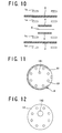
- the casing 8 is explained making a reference to Figure 11, the backside elevation.
- the casing is a generally hollow and cylindrical element, of which backside being a large opening in order that the pair of electrodes 7 are brought into via the large opening.
- the casing 8 has, on the right side in this Figure 11, a pair of cutouts 81 cut at the circumference of its cylindrical portion. These cutouts 81 allows the lug portion of the anode current corrector plate 2 and the lug portion of the cathode current corrector plate 3 to stick out therethrough.
- the cutouts 81 directly communicate or reach the large opening in such a manner that the anode current collector plate 2 and the cathode current collector plate 3 can be brought in the casing 8 and can be placed properly via the large opening and the pair of cutouts 81.
- the front of the casing 8 is for the most part closed but has eight through holes which are to be aligned with the aforementioned eight through holes of the fourth sealing element 1d.
- the front of the casing 8 has the opening 191 to be connected to the suitable pipeline 19 for letting out the mixed fluid of hydrogen gas and water.
- the casing 8 is made of polypropylene.
- the reinforcement plate 14 is generally disk-shaped and has eight through holes in the vicinity of its periphery which are to be aligned with the aforementioned eight through holes of the casing 8.
- the plate 14 also has the aforementioned opening 190 which is to be in alignment with and larger than the opening 191 of the casing 8.
- This reinforcement plate 14 is made of stainless steel of the type "SUS 304" in JIS(Japanese Industrial Standard).
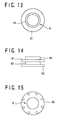
- the tubular connection element 9 has a cylindrical portion 93 which defines its aforementioned inner pass, as is clearly understood referencing the backside view of Figure 13, plan view of Figure 14 and front elevation of Figure 15.
- the element 9 extends radially outwardly at its front end, thereby defining a first doughnut-type disc-shaped portion 92.
- the first doughnut-type disc-shaped portion 92 has eight through holes in the vicinity of its periphery which are to be aligned with the aforementioned eight through holes of the second sealing element 1b. Further, the element 9 extends radially outwardly from the circumference of the cylindrical portion 93, thereby defining a second doughnut-type disc-shaped portion 91.
- the second doughnut-type disc-shaped portion 91 is at the back of and spaced apart from the first doughnut-type disc-shaped portion 92. In the vicinity of the cylindrical portion 93, the backside surface of the second doughnut-type disc-shaped portion 91 can be used as a stopper for the aforementioned 0-ring 10.
- the O-ring is fitted to secure good sealing property when connecting the cell 100 to a container for the aforementioned separation of liquid and gas.
- the connection element 9 is made of poly-tetra-fluoro-ethylene (PTFE), that is a kind of fluororesin.
- the O-ring 10 is made of fluororubber.
- the pair 13 of flanges is a set of two flat members 131 and 132.
- Each of the members 131 and 132 is generally arch-shaped.
- the arch-shaped member 131 has four holes for receiving bolts. These four holes are adapted to be aligned with upper four of the aforementioned eight through holes of the first doughnut-type disc-shaped portion 92.
- the arch-shaped member 132 has four holes for receiving bolts. The four holes of the member 132 are adapted to be aligned with lower four of the aforementioned eight through holes of the first doughnut-type disc-shaped portion 92.
- Each of the four holes of the member 131 and the four holes of the member 132 has a round inner surface which is threaded to properly receive corresponding one of eight bolts 12 which is screwed into the hole.
- the total eight bolts 12 are tightly screwed to fit onto the threaded inner surfaces of the four holes of the member 131 and the four holes of the member 132.
- female threads or nuts corresponding to the bolts 12 are integrally formed with the pair 13 of flanges, forming the four holes for receiving four bolts per each piece of flange.
- the arch-shaped members 131 and 132 are inserted and fitted between the first and second doughnut-type disc-shaped portions 92 and 91.
- each of the arch-shaped members 131 and 132 is shaped to have a part which extends outwardly in a radial direction, more than is necessary to form a mere top portion of the arch.
- Each of the part has a through hole 22 for a bolt which will be tightly screwed into the hole 22 in order to fix and support the tubular connection element 9 onto the outer structure of the aforementioned container for separation of gas from liquid. It is the only two bolts that need to be tightened to fix and support the tubular connection element 9 onto the outer structure of the aforementioned container.
- the two bolts and the arch-shaped members 131 and 132 are made of stainless steel (SUS304).
- the eight bolts 12 can be made of stainless steel (SUS304). Portions of their stems in the neighborhood of their tips are fixed in the female threads of the flanges 13 by screwing. Other portions of the stems are electrically insulated from the aforementioned current collector plates and the electrodes by insulation tubes 11 in which the portions are fitted as shown in Fig. 17.
- the insulation tubes 11 are made of PTFE. Therefore, even when the sealing by the first, the second, the third and the fourth sealing elements are becoming weak and ozone gas or ozone water is leaking towards vicinage of the bolts, the bolts 12 are protected by the corrosion-resistant tubes 11 around the vicinage, enabling to continue the operation as long as the other circumstances permits.
- Figure 18 shows an exploded plan view of one of the tubes 11 and one of the bolts 12.
- An aqueous electrolysis cell 100 for generating ozone gas as shown in Figs. 1-3 was fabricated by assembling the above mentioned parts. Operation test of the cell 100 was carried out in an attitude as shown in the front elevation of Fig. 19 and in the right side view of Fig. 20. In this attitude, the cell was connected to, fixed to, and supported by an external equipment 20 for separation of gas from liquid. After supplying pure water, the electrolysis reaction was started at an electric current density of 100 ampere/dm 2 . 24 hours later, ozone gas concentration of the mixed gas recovered from the anode chamber was 230 g/m 3 .
- the solution is supplied via the external container of the equipment for separating gas from liquid and then via the tubular element 9.
- the supply line of the aqueous solution may be located independently, for instance, as a pipeline directly connecting into the tubular element 9 through the cylindrical surface of the tubular element 9.
- the portion 91 might not be in the donut-type shape but in a shape suitably detouring the supply line.
- the pair of flange 13 might not be limited in the two-part form, that is to say, it can be made as a set of more than two parts, including various changes in forms or shapes.
- the anode was made of porous titanium substrate plated with lead dioxide. However, in a variation, the anode can be made of expanded titanium plated with lead dioxide.
- the cathode was made of porous titanium substrate plated with platinum. However, in a variation, the cathode can be made of expanded titanium plated with platinum. In another variation, carbon electrode might be employed.
- the cell in the above mentioned embodiment is preferably operated in an orientation or attitude with the anode and the cathode separated from each other by a membrane, defining the cathode in the front and the anode in the back.
- the cell can be operated in a lied-down attitude with the anode in the upside.
- an aqueous electrolysis cell in which maintenance labors and costs are greatly reduced because of easy attachment and replacement of the cell to and from the anode trap.
- the cell can be made in a very thin, compact shape. Further, the cell is improved in usage flexibility as compared with conventional ones because the connection structures at the anode trap side can be very simple. Further, in the above embodiment, it is easy to assemble the first sealing element, the anode, the membrane, the anode current collector plate, the second sealing element, the cathode, the third sealing element, the cathode current collector plate and the fourth sealing element by utilizing the insulation tubes 11 as guiding members which increase the working efficiency in positioning of the parts.
Landscapes
- Chemical & Material Sciences (AREA)
- Engineering & Computer Science (AREA)
- Chemical Kinetics & Catalysis (AREA)
- Electrochemistry (AREA)
- Materials Engineering (AREA)
- Metallurgy (AREA)
- Organic Chemistry (AREA)
- Inorganic Chemistry (AREA)
- Electrolytic Production Of Non-Metals, Compounds, Apparatuses Therefor (AREA)
- Electrodes For Compound Or Non-Metal Manufacture (AREA)
Applications Claiming Priority (2)
| Application Number | Priority Date | Filing Date | Title |
|---|---|---|---|
| JP37406998 | 1998-12-28 | ||
| JP37406998A JP3389520B2 (ja) | 1998-12-28 | 1998-12-28 | ガス生成用水電解セル |
Publications (2)
| Publication Number | Publication Date |
|---|---|
| EP1016737A1 true EP1016737A1 (fr) | 2000-07-05 |
| EP1016737B1 EP1016737B1 (fr) | 2002-02-27 |
Family
ID=18503210
Family Applications (1)
| Application Number | Title | Priority Date | Filing Date |
|---|---|---|---|
| EP99310527A Expired - Lifetime EP1016737B1 (fr) | 1998-12-28 | 1999-12-23 | Cellule d'électrolyse pour la production de gaz |
Country Status (4)
| Country | Link |
|---|---|
| US (1) | US6156166A (fr) |
| EP (1) | EP1016737B1 (fr) |
| JP (1) | JP3389520B2 (fr) |
| DE (1) | DE69900936T2 (fr) |
Cited By (2)
| Publication number | Priority date | Publication date | Assignee | Title |
|---|---|---|---|---|
| EP2980277A1 (fr) * | 2014-07-31 | 2016-02-03 | Solco Biomedical Co., Ltd. | Unité de génération d'hydrogène pour produire de l'hydrogène à partir d'eau |
| CN110462105A (zh) * | 2017-03-29 | 2019-11-15 | 蒂森克虏伯伍德氯工程公司 | 碱性水电解装置 |
Families Citing this family (10)
| Publication number | Priority date | Publication date | Assignee | Title |
|---|---|---|---|---|
| JP2010001552A (ja) * | 2008-06-23 | 2010-01-07 | Sanyo Electric Co Ltd | 電解用電極および電解ユニット |
| US8216498B2 (en) * | 2008-09-10 | 2012-07-10 | Boston Scientific Scimed, Inc. | Catheter having a coextruded fluoropolymer layer |
| TW201109475A (en) * | 2009-09-03 | 2011-03-16 | ming-yong Xu | Sealed film electrode electrolytic ozone generator |
| TW201109474A (en) * | 2009-09-03 | 2011-03-16 | ming-yong Xu | Film electrode electrolytic ozone generator |
| WO2014021790A1 (fr) * | 2012-08-01 | 2014-02-06 | Sukij Tridsadeerak | Séparation de l'hydrogène de type wdh1 |
| ES2674952T3 (es) * | 2014-01-13 | 2018-07-05 | Solco Biomedical Co., Ltd. | Aparato portátil para producir agua hidrogenada |
| KR101643129B1 (ko) * | 2015-02-04 | 2016-07-27 | 주식회사 동양이지텍 | 휴대용 수소수기 |
| JP6258566B1 (ja) * | 2016-11-04 | 2018-01-10 | 昌也 城井 | 電解セル、オゾン水噴出装置及び電導性ダイヤモンド電極の製造方法 |
| JP6249200B1 (ja) * | 2016-11-04 | 2017-12-20 | 昌也 城井 | 電解セル及びそれを用いたオゾン水噴出装置 |
| JP7228847B2 (ja) * | 2020-02-14 | 2023-02-27 | パナソニックIpマネジメント株式会社 | 電解液体生成装置 |
Citations (3)
| Publication number | Priority date | Publication date | Assignee | Title |
|---|---|---|---|---|
| US5401371A (en) * | 1992-07-16 | 1995-03-28 | Aisin Seiki Kabushiki Kaisha | Hydrogen generator |
| DE29613308U1 (de) * | 1996-08-01 | 1996-11-07 | FISCHER technology GmbH, 53117 Bonn | Elektrolysezelle, insbesondere zur Erzeugung von Ozon für die Abwasserbehandlung |
| WO1998042617A2 (fr) * | 1997-03-21 | 1998-10-01 | Lynntech, Inc. | Systeme a generateur d'ozone integre |
Family Cites Families (5)
| Publication number | Priority date | Publication date | Assignee | Title |
|---|---|---|---|---|
| JP3304563B2 (ja) * | 1993-10-12 | 2002-07-22 | ペルメレック電極株式会社 | 電解オゾン発生装置 |
| US5427658A (en) * | 1993-10-21 | 1995-06-27 | Electrosci Incorporated | Electrolytic cell and method for producing a mixed oxidant gas |
| DE29504323U1 (de) * | 1995-03-17 | 1996-07-25 | Beyer, Wolfgang, 53359 Rheinbach | Elektrolysezelle zum Herstellen von Ozon bzw. Sauerstoff |
| JP3599488B2 (ja) * | 1996-07-12 | 2004-12-08 | 株式会社神鋼環境ソリューション | ガス反応用セル |
| US5989407A (en) * | 1997-03-31 | 1999-11-23 | Lynntech, Inc. | Generation and delivery device for ozone gas and ozone dissolved in water |
-
1998
- 1998-12-28 JP JP37406998A patent/JP3389520B2/ja not_active Expired - Fee Related
-
1999
- 1999-04-15 US US09/292,387 patent/US6156166A/en not_active Expired - Fee Related
- 1999-12-23 DE DE69900936T patent/DE69900936T2/de not_active Expired - Fee Related
- 1999-12-23 EP EP99310527A patent/EP1016737B1/fr not_active Expired - Lifetime
Patent Citations (3)
| Publication number | Priority date | Publication date | Assignee | Title |
|---|---|---|---|---|
| US5401371A (en) * | 1992-07-16 | 1995-03-28 | Aisin Seiki Kabushiki Kaisha | Hydrogen generator |
| DE29613308U1 (de) * | 1996-08-01 | 1996-11-07 | FISCHER technology GmbH, 53117 Bonn | Elektrolysezelle, insbesondere zur Erzeugung von Ozon für die Abwasserbehandlung |
| WO1998042617A2 (fr) * | 1997-03-21 | 1998-10-01 | Lynntech, Inc. | Systeme a generateur d'ozone integre |
Cited By (7)
| Publication number | Priority date | Publication date | Assignee | Title |
|---|---|---|---|---|
| EP2980277A1 (fr) * | 2014-07-31 | 2016-02-03 | Solco Biomedical Co., Ltd. | Unité de génération d'hydrogène pour produire de l'hydrogène à partir d'eau |
| CN105316698A (zh) * | 2014-07-31 | 2016-02-10 | 索尔科生物医疗株式会社 | 用于生产富氢水的氢气生成单元 |
| CN105316698B (zh) * | 2014-07-31 | 2018-09-28 | 索尔科生物医疗株式会社 | 用于生产富氢水的氢气生成单元 |
| CN110462105A (zh) * | 2017-03-29 | 2019-11-15 | 蒂森克虏伯伍德氯工程公司 | 碱性水电解装置 |
| EP3608445A4 (fr) * | 2017-03-29 | 2021-01-13 | ThyssenKrupp Uhde Chlorine Engineers (Japan) Ltd. | Dispositif d'électrolyse d'eau alcaline |
| CN110462105B (zh) * | 2017-03-29 | 2021-07-06 | 蒂森克虏伯伍德氯工程公司 | 碱性水电解装置 |
| US11267728B2 (en) | 2017-03-29 | 2022-03-08 | Thyssenkrupp Uhde Chlorine Engineers (Japan) Ltd. | Alkaline water electrolysis device |
Also Published As
| Publication number | Publication date |
|---|---|
| JP2000199091A (ja) | 2000-07-18 |
| DE69900936T2 (de) | 2002-09-12 |
| US6156166A (en) | 2000-12-05 |
| EP1016737B1 (fr) | 2002-02-27 |
| JP3389520B2 (ja) | 2003-03-24 |
| DE69900936D1 (de) | 2002-04-04 |
Similar Documents
| Publication | Publication Date | Title |
|---|---|---|
| US6156166A (en) | Electrolysis cell for generation of gas | |
| US8057646B2 (en) | Electrolyser and components therefor | |
| JP2911381B2 (ja) | 水素・酸素発生装置 | |
| US4210511A (en) | Electrolyzer apparatus and electrode structure therefor | |
| CN104955986B (zh) | 电解器装置及其制造方法 | |
| FR2461021A1 (fr) | Cellule electrolytique et electrolyseur bipolaire | |
| CN1189598C (zh) | 电化气体扩散半电池 | |
| MXPA01011385A (es) | Estructura de electrodo. | |
| JP2911380B2 (ja) | 水素・酸素発生装置 | |
| US6761808B1 (en) | Electrode structure | |
| JP2862809B2 (ja) | 水素・酸素発生装置 | |
| JP2008274432A (ja) | 電気化学セル構造体及びその製法 | |
| JP3487696B2 (ja) | 水素・酸素発生装置 | |
| JP6999864B1 (ja) | アルカリ水電解用電解エレメント、及びアルカリ水電解槽 | |
| JPH08325772A (ja) | スパイラル型電気分解用セル | |
| JPS61502967A (ja) | 完全組立電気化学槽 | |
| JP3506825B2 (ja) | 水素・酸素発生装置 | |
| CN220089219U (zh) | 一种氢氧分离电解装置及具有该电解装置的水杯、饮水机 | |
| JPH08134679A (ja) | 固体電解質膜電解装置 | |
| JP7585558B1 (ja) | 電解エレメント、および、アルカリ水電解槽 | |
| EP4667424A1 (fr) | Unité d'électrode sacrificielle et procédé d'application d'une telle unité d'électrode sacrificielle | |
| JP3075958B2 (ja) | 電気分解用セル | |
| JPH09316676A (ja) | 筒型電解セルおよび水素酸素発生装置 | |
| TW200401847A (en) | Fluorine cell | |
| CA3298586A1 (fr) | Dispositif pour la mise en œuvre d'un procédé électrochimique |
Legal Events
| Date | Code | Title | Description |
|---|---|---|---|
| PUAI | Public reference made under article 153(3) epc to a published international application that has entered the european phase |
Free format text: ORIGINAL CODE: 0009012 |
|
| AK | Designated contracting states |
Kind code of ref document: A1 Designated state(s): DE FR GB IT SE |
|
| AX | Request for extension of the european patent |
Free format text: AL;LT;LV;MK;RO;SI |
|
| 17P | Request for examination filed |
Effective date: 20000804 |
|
| 17Q | First examination report despatched |
Effective date: 20001018 |
|
| AKX | Designation fees paid |
Free format text: DE FR GB IT SE |
|
| GRAG | Despatch of communication of intention to grant |
Free format text: ORIGINAL CODE: EPIDOS AGRA |
|
| GRAG | Despatch of communication of intention to grant |
Free format text: ORIGINAL CODE: EPIDOS AGRA |
|
| GRAH | Despatch of communication of intention to grant a patent |
Free format text: ORIGINAL CODE: EPIDOS IGRA |
|
| GRAH | Despatch of communication of intention to grant a patent |
Free format text: ORIGINAL CODE: EPIDOS IGRA |
|
| REG | Reference to a national code |
Ref country code: GB Ref legal event code: IF02 |
|
| GRAA | (expected) grant |
Free format text: ORIGINAL CODE: 0009210 |
|
| AK | Designated contracting states |
Kind code of ref document: B1 Designated state(s): DE FR GB IT SE |
|
| REF | Corresponds to: |
Ref document number: 69900936 Country of ref document: DE Date of ref document: 20020404 |
|
| ET | Fr: translation filed | ||
| PGFP | Annual fee paid to national office [announced via postgrant information from national office to epo] |
Ref country code: SE Payment date: 20021204 Year of fee payment: 4 |
|
| PLBE | No opposition filed within time limit |
Free format text: ORIGINAL CODE: 0009261 |
|
| STAA | Information on the status of an ep patent application or granted ep patent |
Free format text: STATUS: NO OPPOSITION FILED WITHIN TIME LIMIT |
|
| 26N | No opposition filed |
Effective date: 20021128 |
|
| PGFP | Annual fee paid to national office [announced via postgrant information from national office to epo] |
Ref country code: FR Payment date: 20031210 Year of fee payment: 5 |
|
| PGFP | Annual fee paid to national office [announced via postgrant information from national office to epo] |
Ref country code: GB Payment date: 20031217 Year of fee payment: 5 |
|
| PG25 | Lapsed in a contracting state [announced via postgrant information from national office to epo] |
Ref country code: SE Free format text: LAPSE BECAUSE OF NON-PAYMENT OF DUE FEES Effective date: 20031224 |
|
| PGFP | Annual fee paid to national office [announced via postgrant information from national office to epo] |
Ref country code: DE Payment date: 20040102 Year of fee payment: 5 |
|
| EUG | Se: european patent has lapsed | ||
| PG25 | Lapsed in a contracting state [announced via postgrant information from national office to epo] |
Ref country code: GB Free format text: LAPSE BECAUSE OF NON-PAYMENT OF DUE FEES Effective date: 20041223 |
|
| PG25 | Lapsed in a contracting state [announced via postgrant information from national office to epo] |
Ref country code: DE Free format text: LAPSE BECAUSE OF NON-PAYMENT OF DUE FEES Effective date: 20050701 |
|
| GBPC | Gb: european patent ceased through non-payment of renewal fee |
Effective date: 20041223 |
|
| PG25 | Lapsed in a contracting state [announced via postgrant information from national office to epo] |
Ref country code: FR Free format text: LAPSE BECAUSE OF NON-PAYMENT OF DUE FEES Effective date: 20050831 |
|
| REG | Reference to a national code |
Ref country code: FR Ref legal event code: ST |
|
| PG25 | Lapsed in a contracting state [announced via postgrant information from national office to epo] |
Ref country code: IT Free format text: LAPSE BECAUSE OF NON-PAYMENT OF DUE FEES Effective date: 20051223 |