EP1016762A2 - Erdbewegungsmaschine - Google Patents
Erdbewegungsmaschine Download PDFInfo
- Publication number
- EP1016762A2 EP1016762A2 EP99125135A EP99125135A EP1016762A2 EP 1016762 A2 EP1016762 A2 EP 1016762A2 EP 99125135 A EP99125135 A EP 99125135A EP 99125135 A EP99125135 A EP 99125135A EP 1016762 A2 EP1016762 A2 EP 1016762A2
- Authority
- EP
- European Patent Office
- Prior art keywords
- actuator means
- fluid
- hydraulic
- base
- variable displacement
- Prior art date
- Legal status (The legal status is an assumption and is not a legal conclusion. Google has not performed a legal analysis and makes no representation as to the accuracy of the status listed.)
- Ceased
Links
- 239000012530 fluid Substances 0.000 claims abstract description 101
- 238000006073 displacement reaction Methods 0.000 claims abstract description 33
- 230000007935 neutral effect Effects 0.000 description 8
- 238000001816 cooling Methods 0.000 description 5
- 238000010586 diagram Methods 0.000 description 3
- 230000005540 biological transmission Effects 0.000 description 2
- 239000000463 material Substances 0.000 description 2
- 238000000034 method Methods 0.000 description 2
- 229910001018 Cast iron Inorganic materials 0.000 description 1
- 230000004308 accommodation Effects 0.000 description 1
- 230000001010 compromised effect Effects 0.000 description 1
- 230000008878 coupling Effects 0.000 description 1
- 238000010168 coupling process Methods 0.000 description 1
- 238000005859 coupling reaction Methods 0.000 description 1
- 230000003247 decreasing effect Effects 0.000 description 1
- 230000001627 detrimental effect Effects 0.000 description 1
- 238000001914 filtration Methods 0.000 description 1
- 238000012986 modification Methods 0.000 description 1
- 230000004048 modification Effects 0.000 description 1
- 230000002028 premature Effects 0.000 description 1
- 230000008569 process Effects 0.000 description 1
- 239000003381 stabilizer Substances 0.000 description 1
- 238000011144 upstream manufacturing Methods 0.000 description 1
Images

Classifications
-
- E—FIXED CONSTRUCTIONS
- E02—HYDRAULIC ENGINEERING; FOUNDATIONS; SOIL SHIFTING
- E02F—DREDGING; SOIL-SHIFTING
- E02F9/00—Component parts of dredgers or soil-shifting machines, not restricted to one of the kinds covered by groups E02F3/00 - E02F7/00
- E02F9/08—Superstructures; Supports for superstructures
- E02F9/0858—Arrangement of component parts installed on superstructures not otherwise provided for, e.g. electric components, fenders, air-conditioning units
- E02F9/0891—Lids or bonnets or doors or details thereof
-
- E—FIXED CONSTRUCTIONS
- E02—HYDRAULIC ENGINEERING; FOUNDATIONS; SOIL SHIFTING
- E02F—DREDGING; SOIL-SHIFTING
- E02F3/00—Dredgers; Soil-shifting machines
- E02F3/04—Dredgers; Soil-shifting machines mechanically-driven
- E02F3/28—Dredgers; Soil-shifting machines mechanically-driven with digging tools mounted on a dipper- or bucket-arm, i.e. there is either one arm or a pair of arms, e.g. dippers, buckets
- E02F3/30—Dredgers; Soil-shifting machines mechanically-driven with digging tools mounted on a dipper- or bucket-arm, i.e. there is either one arm or a pair of arms, e.g. dippers, buckets with a dipper-arm pivoted on a cantilever beam, i.e. boom
- E02F3/32—Dredgers; Soil-shifting machines mechanically-driven with digging tools mounted on a dipper- or bucket-arm, i.e. there is either one arm or a pair of arms, e.g. dippers, buckets with a dipper-arm pivoted on a cantilever beam, i.e. boom working downwardly and towards the machine, e.g. with backhoes
- E02F3/325—Backhoes of the miniature type
-
- E—FIXED CONSTRUCTIONS
- E02—HYDRAULIC ENGINEERING; FOUNDATIONS; SOIL SHIFTING
- E02F—DREDGING; SOIL-SHIFTING
- E02F3/00—Dredgers; Soil-shifting machines
- E02F3/04—Dredgers; Soil-shifting machines mechanically-driven
- E02F3/28—Dredgers; Soil-shifting machines mechanically-driven with digging tools mounted on a dipper- or bucket-arm, i.e. there is either one arm or a pair of arms, e.g. dippers, buckets
- E02F3/36—Component parts
- E02F3/38—Cantilever beams, i.e. booms;, e.g. manufacturing processes, forms, geometry or materials used for booms; Dipper-arms, e.g. manufacturing processes, forms, geometry or materials used for dipper-arms; Bucket-arms
- E02F3/382—Connections to the frame; Supports for booms or arms
- E02F3/384—Connections to the frame; Supports for booms or arms the boom being pivotable relative to the frame about a vertical axis
-
- E—FIXED CONSTRUCTIONS
- E02—HYDRAULIC ENGINEERING; FOUNDATIONS; SOIL SHIFTING
- E02F—DREDGING; SOIL-SHIFTING
- E02F3/00—Dredgers; Soil-shifting machines
- E02F3/04—Dredgers; Soil-shifting machines mechanically-driven
- E02F3/96—Dredgers; Soil-shifting machines mechanically-driven with arrangements for alternate or simultaneous use of different digging elements
- E02F3/963—Arrangements on backhoes for alternate use of different tools
- E02F3/964—Arrangements on backhoes for alternate use of different tools of several tools mounted on one machine
-
- E—FIXED CONSTRUCTIONS
- E02—HYDRAULIC ENGINEERING; FOUNDATIONS; SOIL SHIFTING
- E02F—DREDGING; SOIL-SHIFTING
- E02F9/00—Component parts of dredgers or soil-shifting machines, not restricted to one of the kinds covered by groups E02F3/00 - E02F7/00
- E02F9/08—Superstructures; Supports for superstructures
- E02F9/0858—Arrangement of component parts installed on superstructures not otherwise provided for, e.g. electric components, fenders, air-conditioning units
- E02F9/0866—Engine compartment, e.g. heat exchangers, exhaust filters, cooling devices, silencers, mufflers, position of hydraulic pumps in the engine compartment
Definitions
- This invention relates to an earth moving apparatus and more particularly to such an apparatus of the kind adapted to move over the ground, and having a working arm with an earth working implement.
- Such apparatus are well known.
- Such an apparatus typically has a body mounted for pivotal slewing movement on a base, the base having wheels, tracks or other ground engaging propulsion means, and the working arm being carried on the body for swinging movement about a generally upright axis, e.g. on a king post.
- the body typically mounts an operator's cab, from which cab an operator may drive the apparatus over the ground, and control the operating functions of the working arm and other services.
- the working arm typically is mounted at a front end of the body and an engine of the apparatus, which powers the apparatus, is usually mounted at or towards a rear end of the body, to act as a counterweight to the working arm.
- An additional counterweight may be provided at the rear end if desired.
- Zero swing apparatus So called "zero swing" apparatus are known in which the body may be pivoted relative to the base without any body part extending outwardly of the base.
- such apparatus have a small (short) operator's cab which in many case do not comply with European standards at least.
- the engine could be positioned more centrally of the apparatus, but this would require the operator's cab to be raised up to accommodate the engine beneath, but this is undesirable because there would then be a height restriction detrimental to the usefulness of the apparatus, and the operator may be too high efficiently to operate the working arm.
- An earth moving apparatus of the kind with which the invention is concerned typically has other hydraulically operated services too, such as for examples a dipper arm at the outer end of which there is provided the excavating bucket or other tool which may also be hydraulically operated, an earth moving or "dozer” blade which is extendible/retractable and/or raisable and lowerable, for pushing earth or other ground material, and other auxiliary services too.
- other hydraulically operated services such as for examples a dipper arm at the outer end of which there is provided the excavating bucket or other tool which may also be hydraulically operated, an earth moving or “dozer” blade which is extendible/retractable and/or raisable and lowerable, for pushing earth or other ground material, and other auxiliary services too.
- the fluid pressure and volume requirements for a fluid operated actuator designed to move e.g. a working arm relative to a body of an earth moving apparatus about an upright axis for example, are substantially different to the requirements of a fluid operated transmission for powering a ground engaging propulsion means.
- variable displacement fluid pump for providing pressurised fluid for a first set of the hydraulic actuating means, such as for driving the ground engaging propulsion means, operating the working implement at an outer end of the working arm, for moving the working arm relative to the body about a generally horizontal axis, and for moving a dipper of the working arm relative to a boom of the working arm, about another generally horizontal axis, but for there to be a separate pump, such as a gear pump driven from an output shaft of the engine, to provide pressurised fluid for another, second set of, services such as the actuator or actuators of an earth moving blade, actuator means for moving the working arm relative to the base about an upright axis, and actuator means for moving the body relative to the base about an upright axis.
- a first set of the hydraulic actuating means such as for driving the ground engaging propulsion means, operating the working implement at an outer end of the working arm, for moving the working arm relative to the body about a generally horizontal axis, and for moving a dipper of the working arm relative to a boom of
- the first set of services for which hydraulic fluid is provided from the variable displacement pump may be operated without affecting the supply of hydraulic fluid to the second set of services to which hydraulic fluid is provided from the auxiliary pump.
- variable displacement pump two such separate pumps each require space. Where the separate pump is driven from the engine output shaft, from which the variable displacement pump too is driven, a substantial longitudinally extending space would be required to accommodate the variable displacement and auxiliary pumps. Such space may not readily be available in the case of a small excavator, and particularly but not exclusively so in the case of an apparatus in accordance with which the present invention is concerned.
- an earth moving apparatus having a base including a ground engaging propulsion means whereby the apparatus may move over the ground, first hydraulic actuator means to drive the ground engaging propulsion means, a body carried on the base, second hydraulic actuator means for moving the body relative to the base about a first generally upright axis, a working arm connected at or towards one end thereof to the body, third actuator means for moving the working arm relative to the body about a second generally upright axis and fourth hydraulic actuator means for moving the working arm relative to the body about a generally horizontal axis, and the working arm carrying at or towards a second outer end thereof, an earth working implement, fifth hydraulic actuator means to move the working implement about a second generally horizontal axis, characterised in that the first, second, third, fourth and fifth hydraulic actuator means are provided with pressurised hydraulic fluid by a single variable displacement pump.
- the hydraulic pump to provide pressurised hydraulic fluid is preferably mounted in an engine compartment of the apparatus, preferably between the engine and a first end of the body, so as to be drivable directly from the engine.
- the body may be movable relative to the base about the first generally upright axis, through substantially 360°, through a datum position in which the first end of the body is at a front end of the base.
- the ground engaging means of the apparatus preferably includes a pair of tracks, each track of the pair being positioned at a side of the base, whereby edges of the tracks define the width of the base and hence of the apparatus at least when the body is in its datum position.
- the working arm may include a boom mounted on the body, and a dipper which is adapted to carry the working implement, the dipper being movable relative to the boom about a third generally horizontal axis, by sixth hydraulic actuator means to which pressurised hydraulic fluid may be provided from the variable displacement pump, via the fluid control means.
- the apparatus may further include an earth moving blade which is mounted on the base, and there is a seventh hydraulic actuator means for causing up and down movement of the blade about a fourth generally horizontal axis, in which case, to avoid providing a separate pump, the seventh actuator means may be provided with pressurised hydraulic fluid for operation, from the variable displacement pump, via the hydraulic fluid control means.
- variable displacement pump By virtue of a single variable displacement pump being used to provide hydraulic fluid for all of the services, greater flexibility in the design of the apparatus is thus possible, facilitating the positioning of the engine in the compartment at or towards the side of the body.
- variable displacement pump is arranged to supply a stand-by flow of pressurised fluid when all of the hydraulic actuator means are de-activated.
- the pump is a swashplate pump
- a stop means may conveniently be provided to prevent the swashplate moving to a fully unloaded position.
- unloading valve means may be provided to permit the stand-by flow to be communicated to a fluid return line of the fluid control means and to prevent the flow of fluid to the fluid return line when a fluid actuating means is operated.
- means may be provided to maintain the fluid pressure in the fluid return line above a minimum pressure.
- the stand-by flow may be communicated to the hydraulic motor to assist in braking the momentum of the rotating body when the first actuator means is de-activated.
- Preferably means are provided to prevent the variable displacement pump from providing fluid at its maximum operating pressure in the event that the first and/or second actuator means is operated in combination with at least one of the third, fourth and fifth actuator means.
- mini we mean an excavator having a weight of between 1 and 6 tons.
- micro excavator
- midi excavator which typically has a weight of between 6 and up to about 10 tons.
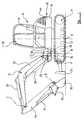
- the apparatus 10 shown in the drawings comprises a base 11 having a ground engaging propulsion means, which in this example includes a pair of tracks 12,13, one positioned at each side of the base 11.
- the tracks 12,13 are driven by through a transmission by first hydraulic fluid operated actuator means, such as a pair of hydraulic motors 60,61 for example.
- first hydraulic fluid operated actuator means such as a pair of hydraulic motors 60,61 for example.
- body 15 On the base 11 there is a body 15, which is mounted so as to be slewable, in this example fully rotatable, about a first generally upright axis A with respect to the base 11, about 360°, by means of a second hydraulic actuator means, e.g. a further hydraulic motor 65 or other hydraulic motive means.
- the body 15 further comprises a full size operator's cab 18, by which we mean a cab 18 which complies with European standards for size. From the cab 18, an operator, when seated on a seat 16 therein, may control the apparatus 10 by operating controls.
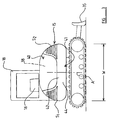
- the body 15 is shown in a datum position relative to the base 11, i.e. with the body 15 facing forwardly of the direction of travel of the apparatus using the tracks 12,13, and with an operator in the cab 18 facing forwardly.
- the boom 22 is mounted at one end 25 thereof to the body 15 in a manner to permit of swinging movement of the arm 21 about a second generally upright axis B, e.g. by virtue of a king post 17 mounting, as well as lifting and lowering movement of the arm 21 about a first generally horizontal axis C.
- Standard excavators i.e. excavators having a weight above about 10 tons which are designed for heavier duty excavating work, usually have a working arm which is liftable and lowerable, but not swingable as is the working arm of a "micro”, “mini” or “midi” excavator, as is it not so essential that a standard excavator is capable of working in such a versatile manner in confined conditions.
- third hydraulic actuator means which in this example is one or a pair of hydraulic fluid operated linear actuators 26, and lifting and lowering of the arm 21 about axis C is achieved by a fourth hydraulic actuator means which in this example is a single hydraulic fluid operated linear actuator 28, the actuators 26, 28 acting between the body 15 and the arm 21.
- a working implement comprising in this example an excavating bucket 30, but in another example may be a hammer or drill attachment which is hydraulically operated.
- the bucket 30 is movable with respect to the dipper 24 about a second generally horizontal axis D, by means of a fifth hydraulic actuator means which in this example is a linear actuator 31.
- the dipper 24 and boom 22 are pivotally connected for movement about a third generally horizontal axis E, by means of a sixth hydraulic actuator means which in this example is yet another hydraulic fluid operated linear actuator 33.
- the apparatus 10 further comprises a dozer blade 35 mounted on the base 11 which blade 35 is movable up and down about a fourth generally horizontal axis F by means of seventh hydraulic actuator means which in this example again comprises a pair of linear actuators 36.
- the operator's cab 18 is provided at one side S1 of the body 15.
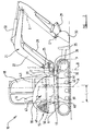
- an engine compartment 38 which houses an engine 39, the position of which is indicated in figures 2 and 4.
- the engine 39 has a length dimension L and is arranged generally longitudinally so that the engine 39 occupies a minimum width of the body 15.
- the overall length of the body 15 can be minimised without compromising the body length space available for the operator's cab 18. It is desirable though for the cab 18 not to be positioned too far rearwardly of the body 15, or else this can leave the cab 18 vulnerable to damage in the event that the body 15 is slewed about axis A too close to an obstacle, as the cab 18 rather than a rear body part could strike the obstacle. Also, accommodation is still required for other operating parts of the apparatus 10
- a compartment 40 which is of small capacity compared to the capacity of engine compartment 38.
- the rear compartment 40 is used to house hydraulic equipment for which there is insufficient room in the engine compartment 38.
- the rear compartment 40 may have within it a hydraulic fluid cooling pack 70, including a radiator for cooling the fluid, and other hydraulic equipment.
- a hydraulic pump 43 is provided in the engine compartment 38 as described hereinafter in more detail.
- the rear compartment 40 is provided by bodywork and thus in the event that the body 15 is slewed about axis A too close to an obstacle, the bodywork rather than the cab 18 will strike the obstacle, thus providing some protection for the cab 18.
- the engine 39 of the apparatus where mounted at the rear 41 of the body 15 will provide some counterweighting for the working arm 21, but by providing the engine 39 to the side of the cab 18, this counterweighting is reduced.
- a part of a rear bodywork wall 42 of the rear compartment 40 is provided by a counterweight 44 which is shaped to a desired body contour and thus is an integral part of the body 15.
- the counterweight 44 extends across the rear end 41 of the body 15 and around the sides S1, S2 in this example.
- the counterweight 44 is typically of cast iron or similar heavy material, and counterbalances the working arm 21 and any load imposed on the working arm 21 in use, as well as providing a tough primary surface to strike an obstacle in the event that the body 15 is slewed about axis A too close to the obstacle..
- a hydraulic pump In a conventional small excavating machine, i.e. a machine smaller than a standard machine, a hydraulic pump, usually a variable capacity hydraulic pump such as a swashplate pump, is used to provide a source of pressurised hydraulic fluid for some of the services of the machine, such as the first actuating means which drives the ground engaging propulsion means, the fourth actuating means i.e. actuator 28, the fifth actuator means i.e. actuator 31, and the sixth actuator means i.e. the dipper actuator 33.
- a single variable displacement pump hydraulic pump 43 is provided which is driven directly from an output shaft 45 of the engine 39.
- variable displacement hydraulic pump indicated at 43 is used to provide pressurised hydraulic fluid for each of the first to seventh actuator means.
- a fluid control valve means which will retain the required pressure and/or flow to one or more selected actuator means in the event that another of the actuator means is operated or is stopped from operating.
- an engine cooling apparatus 48 which typically comprises a bulky radiator 49 and a fan 50 to move cooling air over fins of the radiator 49, is positioned rearwardly of the engine 39 where the height required for this will not obstruct an operator's forward or side visibility.
- the radiator 49 may extend rearwardly towards or even partially within the rear compartment 40.
- no part of the body 15 extends outwardly beyond the width W or length of the base 11 when the body 15 is in the datum position. Even when the body 15 is rotated about the first generally upright axis A from the datum position, preferably no part of the body 15 extends substantially outwardly of the base 11.
- the counterweight 44 is shaped to be rounded to maximise the clearance between the rear 41 of the body 15 and an adjacent obstacle during such movement.
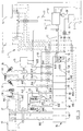
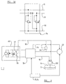
- FIG. 5a there is shown a hydraulic circuit which is adapted to enable a single variable displacement hydraulic pump 43 to be used to provide hydraulic fluid to each of the various hydraulic actuator means.
- operator controls may be provided for operating the hydraulic actuators.
- a pair of joystick type operator controls 73, 74 are mounted, one on each arm of the operator's seat 16, the operator controls 73,74 being operable to operate various of the hydraulic actuator means described above via hydraulic control lines.
- Further manual controls are provided for the first actuator means (track 12,13 drive motors 60,61) and for controlling boom 22 swing about upright axis B, and for lifting and lowering the dozer blade 35 and for providing auxiliary hydraulic flow as indicated at 71.
- a hydraulic fluid control line 75 extends from a main pressure line 76 from the pump 43 via a pressure reducing valve means 77 to provide pressurised hydraulic fluid to each of the controls 73, 74, and depending on the positioning of the joystick controls 73, 74, hydraulic signals are sent via hydraulic control lines indicated generally at L, to a valve block 78 which includes a part 80 to 87 with a chamber containing a spool or spools for each control function. Those spools which are not hydraulically moveable as a result of the operation of controls 73, 74 are manually moveable.
- the main pressure line 76 is connected to each of the valve block parts 80 to 87 within the valve block 78 in a circuit (not shown) whereby pressurised hydraulic fluid is fed to the respective spool-containing chambers of the valve block parts 80 to 87, which depending on the position of the spool or spools therein, may direct the fluid to a respective actuator means 60,61;65;26;28;31;33; and 36.
- a fluid return or neutral line 90 by means of which hydraulic fluid from the various actuators 60,61;65;26;28;31;33; and 36 or pumped fluid not required, is returned to tank T via the hydraulic fluid cooler 70, and a filter 91.
- a foot and/or hand operated manual control not shown is provided in the operator's cab 18 which is separate from the joystick controls 73, 74, for controlling the first actuator means i.e. the track motors 60, 61 which may be adapted to operate either in high speed or low speed mode.
- control lines L from the joystick controls 73, 74 are also arranged in pairs as will now more specifically be described.
- a pair 81a and 81b from the left control 73 are connected to an associated part 81 of the valve block 78 which contains a spool or spools for directing pressurised fluid from the main pressure line 76 to the second actuator means 65 i.e. the slew motor, depending on the position of the control 73.
- V/here a hydraulic signal is sent along line 81a to the valve block part 81 the spool/spools therein respond by allowing operating fluid from the main pressure line 76 from the pump 43 to be sent to the slew motor 65 along an operating line 81c to move the slew motor 65 in one direction of rotation, whereas a hydraulic signal sent along the line 81b to the valve block part 81 results in an operating fluid from the main pressure line 76 being sent to the slew motor 65 along another operating line 81d to move the slew motor 65 in an opposite direction of rotation. Operation of the slew motor will be described in more detail below.
- a further manual control is provided in cab 18 by means of which an operator may control swing ram 26.
- a spool or spools may be moved therein by the manual control to direct operating fluid from the main pressure line 76 from the pump 43 to one or other of a pair of third fluid lines 82c, 82d to operate the second hydraulic actuator means or swing ram 26 to swing the boom 22 about second upright axis B under manual control.
- a second pair of control lines 83a and 83b from the right joystick control 74 may send control hydraulic signals from the control 74 to a fourth part 83 of the valve block 78, to move a spool or spools therein to direct operating fluid from the main pressure line 76 to one or other of a pair of fourth fluid lines 83c, 83d to operate the fourth hydraulic actuator means or boom ram 28.
- a third pair of control lines 84a and 84b from the right joystick control 74 may send control hydraulic signals from the control 74 to a fifth part 84 of the valve block 78 to move a spool or spools therein to direct operating fluid from the main pressure line 76 from the pump 43 to one or other of a pair of fifth operating fluid lines 84c, 84d to operate the fifth hydraulic actuator means or bucket/crowd ram 31 to operate the excavating implement 30.
- a fourth pair of control lines 85a and 85b from the left joystick control 73 may send control hydraulic signals from the control 73 to a sixth part 85 of the valve block 78 to move a spool or spools therein to direct operating fluid from the main pressure line 76 from the pump 43 to one or other of a pair of sixth operating fluid lines 85c, 85d to operate the sixth hydraulic actuator means or dipper ram 33 to move the dipper 24 about axis D relative to the boom 22.
- a yet further manual control may be provided in the cab 18 connected to a seventh part 86 of the valve block 78 to move a spool or spools therein to direct operating fluid from the main pressure line 76 from the pump 43 to one of a pair of seventh operating fluid lines 86c, 86d to operate the seventh hydraulic actuating means or dozer rams 36 to operate to earth moving shovel 35.
- the dozer rams 36 being provided on base 11 are fed with operating fluid via the rotating joint J.
- the pump 43 in the event that the joysticks 73, 74 and other controls are moved or allowed to move to an inoperative position such that each of the actuator means is de-activated, the pump 43 is arranged to respond by reducing the flow of fluid produced thereby and vice versa.
- the pump 43 senses a pressure in a load sensing line 91 and changes the angle of the swashplate accordingly to provide a pressure/flow to match the pressure/flow requirements of the fluid operating means as a whole.
- all the actuator means are de-activated i.e. at rest, usually, no flow results.
- the swashplate angle is changed to produce the desired flow/pressure for that or those services.
- a conventional slew motor of the kind shown at 65 requires a supply of hydraulic pressure when the motor 65 is de-activated, in order to brake the momentum of the rotating body 15. Otherwise, the slew motor 65 could well cavitate causing premature motor wear and presenting possible danger.
- a supply of pressurised hydraulic fluid will always be available.
- variable displacement pump 43 is adapted always to provide a supply of pressurised fluid even when no hydraulic service is calling for such fluid (i.e. the various controls are all in a rest condition). In the case of a swashplate pump 43, this may simply be achieved by providing a stop to prevent the swashplate assuming a fully unloaded position, or zero angle.
- the pressurised fluid thus produced in main supply line 76 is fed via an unloading valve 94 into the neutral line 90 from where the pressurised fluid is transmitted back via neutral or return line 95 from the slew motor 65, to the slew motor 65.
- Such supply may feed anti-cavitation valves 96, 97 associated with the slew motor 65 to prevent cavitation and to enable the momentum of the rotating body 15 to be braked.
- a check valve 100 which is set to maintain a fluid pressure in the return or neutral line 90 greater than the minimum required to supply the slew motor 65.
- the unloader valve 94 is sensitive to the pressure in the load sensing line 91 and only opens to permit fluid from the main pressure line 76 to pass into the neutral line 90 when or as the swashplate of the pump 43 is moved to or at least close to its unloaded minimum (stopped) flow position, as a result of sensing a minimum or zero pressure in load sensing line 91.
- Supplying pressurised fluid to the neutral line 90 as described not only prevents cavitation of the slew motor 65 and permits the momentum of the body 15 to be braked, but also provides other benefits.
- a "stand-by" flow of fluid from the neutral line 90 assists in de-aerating and filtering of the hydraulic fluid.
- the fluid will continue to be cooled.
- a relief valve may be caused suddenly to relieve the fluid pressure to prevent damage to the fluid control system and/or stalling of the engine 39. This relief is sensed in load sensing line 91 and as a result the swashplate angle in the pump 43 will be decreased suddenly. This will affect the speed of slewing or tracking. This can be disconcerting for an operator where such slowing down occurs rapidly.
- the fluid control means has a compensating means, preferably associated with parts 80 and 81 of the valve block 78, to limit the maximum pressure available when combining slewing or track driving with other services so that there is less likelihood of the relief valve operating.
- an apparatus 10 with an alternative working arm to that shown at 21 may be provided in which case all of the actuators 26, 28, 33 need not be required or indeed more actuators may be required.
- An alternative working implement to the bucket 30 shown may be used.
- the base 11 may have lowerable stabilisers, actuated by auxiliary actuators as indicated at 71, which may be operated by pressurised hydraulic fluid from the single variable displacement hydraulic pump 43 via yet another part 87 of the valve block 78, under manual or hydraulic control.
Landscapes
- Engineering & Computer Science (AREA)
- Mining & Mineral Resources (AREA)
- Civil Engineering (AREA)
- General Engineering & Computer Science (AREA)
- Structural Engineering (AREA)
- Mechanical Engineering (AREA)
- Operation Control Of Excavators (AREA)
- Agricultural Machines (AREA)
Applications Claiming Priority (2)
| Application Number | Priority Date | Filing Date | Title |
|---|---|---|---|
| GB9827558 | 1998-12-16 | ||
| GB9827558A GB2344809B (en) | 1998-12-16 | 1998-12-16 | Earth moving apparatus |
Publications (2)
| Publication Number | Publication Date |
|---|---|
| EP1016762A2 true EP1016762A2 (de) | 2000-07-05 |
| EP1016762A3 EP1016762A3 (de) | 2000-10-25 |
Family
ID=10844232
Family Applications (1)
| Application Number | Title | Priority Date | Filing Date |
|---|---|---|---|
| EP99125135A Ceased EP1016762A3 (de) | 1998-12-16 | 1999-12-16 | Erdbewegungsmaschine |
Country Status (2)
| Country | Link |
|---|---|
| EP (1) | EP1016762A3 (de) |
| GB (1) | GB2344809B (de) |
Families Citing this family (2)
| Publication number | Priority date | Publication date | Assignee | Title |
|---|---|---|---|---|
| US7383906B2 (en) | 2002-08-29 | 2008-06-10 | Jlg Industries, Inc. | Rotatable and telescopic work machine |
| GB0710155D0 (en) * | 2007-05-26 | 2007-07-04 | Bamford Excavators Ltd | Working machine |
Family Cites Families (13)
| Publication number | Priority date | Publication date | Assignee | Title |
|---|---|---|---|---|
| FR1457633A (fr) * | 1964-09-22 | 1966-01-24 | Sperry Rand Corp | Système pour l'alimentation et la commande d'un équipement hydraulique |
| IT1195178B (it) * | 1986-09-24 | 1988-10-12 | Chs Vickers Spa | Sistema di recupero di portata per circuiti idraulici con pompe e di stributori compensati in pressione per organi di lavoro di macchine movimento terra |
| JPH076217B2 (ja) * | 1987-10-09 | 1995-01-30 | 日立建機株式会社 | 全旋回式作業機 |
| EP0362402B1 (de) * | 1988-03-03 | 1997-09-03 | Hitachi Construction Machinery Co., Ltd. | Verfahren und vorrichtung zum antrieb einer hydraulischen vorrichtung |
| GB8810886D0 (en) * | 1988-05-09 | 1988-06-15 | Knackstedt J S | Material handling machine |
| US5046312A (en) * | 1988-07-08 | 1991-09-10 | Kubota, Ltd. | Swivel speed control circuit for working vehicle |
| JPH02125033A (ja) * | 1988-11-02 | 1990-05-14 | Kubota Ltd | 作業車の油圧アクチュエータ操作構造 |
| JP2619128B2 (ja) * | 1990-08-28 | 1997-06-11 | 株式会社クボタ | バックホウの油圧回路構造 |
| GB2268155B (en) * | 1992-06-30 | 1996-10-02 | Artix Ltd | Material handling machine |
| JPH08135789A (ja) * | 1994-11-09 | 1996-05-31 | Komatsu Ltd | 車両の油圧式駆動装置の変速装置およびその変速制御方法 |
| KR100236117B1 (ko) * | 1996-01-30 | 1999-12-15 | 세구치 류이치 | 스윙식 유압쇼벨 |
| JP3501902B2 (ja) * | 1996-06-28 | 2004-03-02 | コベルコ建機株式会社 | 建設機械の制御回路 |
| EP0900888B1 (de) * | 1996-12-03 | 2006-05-24 | Shin Caterpillar Mitsubishi Ltd. | Steuerungsvorrichtung für eine arbeitsmaschine |
-
1998
- 1998-12-16 GB GB9827558A patent/GB2344809B/en not_active Expired - Lifetime
-
1999
- 1999-12-16 EP EP99125135A patent/EP1016762A3/de not_active Ceased
Also Published As
| Publication number | Publication date |
|---|---|
| GB2344809A (en) | 2000-06-21 |
| EP1016762A3 (de) | 2000-10-25 |
| GB9827558D0 (en) | 1999-02-10 |
| GB2344809B (en) | 2002-10-02 |
Similar Documents
| Publication | Publication Date | Title |
|---|---|---|
| JP5340032B2 (ja) | 作業機 | |
| US7162869B2 (en) | Hydraulic system for a work machine | |
| EP2673422B1 (de) | Zur integration in einen bagger konfiguriertes hydrostatisches system | |
| US9850640B2 (en) | Working machine | |
| EP1126088B1 (de) | Hydraulische Anordnung zur Dämpfung der Trägheitskraft | |
| JP3221268B2 (ja) | 油圧ショベルの油圧回路 | |
| GB2395187A (en) | Excavating and loading machine | |
| JP4480565B2 (ja) | バックホウの油圧回路構造 | |
| US6357231B1 (en) | Hydraulic pump circuit for mini excavators | |
| JP6781181B2 (ja) | 伸縮アームを有する作業機械 | |
| EP1979626A2 (de) | Hydraulisches mehrzwecksystem | |
| EP3795753B1 (de) | Arbeitsmaschine | |
| JP2009293631A (ja) | 作業機の油圧システム | |
| EP3425127B1 (de) | Hydrauliksystem für arbeitsmaschine | |
| US10858799B2 (en) | Tool stabilizer system | |
| JP3469279B2 (ja) | 液圧回路 | |
| JP5313564B2 (ja) | 作業機の走行用操作装置 | |
| GB2344809A (en) | Earth moving apparatus | |
| JP2004092247A (ja) | 建設機械の油圧駆動装置 | |
| JP2005147326A (ja) | 作業機械 | |
| JP4298674B2 (ja) | 建設機械の油圧駆動装置 | |
| CN114746612A (zh) | 作业机 | |
| JP3337939B2 (ja) | 建設機械の油圧駆動装置 | |
| JPH08128066A (ja) | バックホウにおけるドーザ昇降用油圧シリンダの取付け構造 | |
| JPH08209738A (ja) | バックホウにおけるドーザ昇降用油圧シリンダの取付け構造 |
Legal Events
| Date | Code | Title | Description |
|---|---|---|---|
| PUAI | Public reference made under article 153(3) epc to a published international application that has entered the european phase |
Free format text: ORIGINAL CODE: 0009012 |
|
| AK | Designated contracting states |
Kind code of ref document: A2 Designated state(s): DE FR GB IT |
|
| AX | Request for extension of the european patent |
Free format text: AL;LT;LV;MK;RO;SI |
|
| PUAL | Search report despatched |
Free format text: ORIGINAL CODE: 0009013 |
|
| AK | Designated contracting states |
Kind code of ref document: A3 Designated state(s): AT BE CH CY DE DK ES FI FR GB GR IE IT LI LU MC NL PT SE |
|
| AX | Request for extension of the european patent |
Free format text: AL;LT;LV;MK;RO;SI |
|
| RIC1 | Information provided on ipc code assigned before grant |
Free format text: 7E 02F 9/12 A, 7E 02F 9/22 B |
|
| 17P | Request for examination filed |
Effective date: 20010411 |
|
| AKX | Designation fees paid |
Free format text: DE FR GB IT |
|
| 17Q | First examination report despatched |
Effective date: 20020822 |
|
| STAA | Information on the status of an ep patent application or granted ep patent |
Free format text: STATUS: THE APPLICATION HAS BEEN REFUSED |
|
| 18R | Application refused |
Effective date: 20041203 |