EP1016773A2 - Kühlbare Schaufel für eine Gasturbine - Google Patents
Kühlbare Schaufel für eine Gasturbine Download PDFInfo
- Publication number
- EP1016773A2 EP1016773A2 EP99811183A EP99811183A EP1016773A2 EP 1016773 A2 EP1016773 A2 EP 1016773A2 EP 99811183 A EP99811183 A EP 99811183A EP 99811183 A EP99811183 A EP 99811183A EP 1016773 A2 EP1016773 A2 EP 1016773A2
- Authority
- EP
- European Patent Office
- Prior art keywords
- blade
- blow
- blade root
- slot
- cooling medium
- Prior art date
- Legal status (The legal status is an assumption and is not a legal conclusion. Google has not performed a legal analysis and makes no representation as to the accuracy of the status listed.)
- Granted
Links
Images



Classifications
-
- F—MECHANICAL ENGINEERING; LIGHTING; HEATING; WEAPONS; BLASTING
- F01—MACHINES OR ENGINES IN GENERAL; ENGINE PLANTS IN GENERAL; STEAM ENGINES
- F01D—NON-POSITIVE DISPLACEMENT MACHINES OR ENGINES, e.g. STEAM TURBINES
- F01D5/00—Blades; Blade-carrying members; Heating, heat-insulating, cooling or antivibration means on the blades or the members
- F01D5/12—Blades
- F01D5/14—Form or construction
- F01D5/18—Hollow blades, i.e. blades with cooling or heating channels or cavities; Heating, heat-insulating or cooling means on blades
- F01D5/187—Convection cooling
Definitions
- the invention relates to a coolable blade for a gas turbine or the like according to the preamble of claim 1.
- Such a blade is known, for example, from US Pat. No. 5,498,133 the invention is based. It is essentially one shovel blade, one Blade base and a blade root built.
- the airfoil has one suction-side and a pressure-side wall, which have a front and a rear edge are interconnected.
- the walls define the profile shape and enclose within a cavity that is used for cooling purposes.
- At least one cooling channel is integrated, which is usually from a cooling medium air is flowing through.
- the blade is basically sufficient to cool and thus achieve the designed service life.
- the exhaust openings in the area of the rear edge are drilled, cast, eroded, etched or produced in another way and penetrate the wall section from the cooling channel to the outer surface.
- the cooling medium reduces the wall temperature through heat conduction and thereby improves component life.
- the trailing edge area is particularly critical in this context the blade root, which is often the one that limits lifespan Area of the shovel proves. Despite the reduction in wall temperatures leads to the creation of blow-out openings in the area of the rear edge Increase in stress.
- the invention tries to avoid the disadvantages described. You are the Task based on a coolable blade for a gas turbine or the like of the type mentioned at the outset, which has an increased service life and with which it succeeds, in particular the mechanical and thermal loads in the trailing edge area of the blade root.
- the blade root at least in the area the trailing edge has a concavely curved contour and one the blow-out openings are arranged as blow-out slots on the blade root.
- the outlet slot extends radially in the exit plane at the rear edge Direction at least over the entire area of the blade root and has a cross-sectional shape that at least in the exit plane of the contour the blade root follows so far that wall sections with approximately constant Wall thickness arise.
- the objective is pursued, on the one hand, the temperature load this critical point and thus lower the wall temperature.
- the stress concentration is reduced by adapting the contour as a result, notch effect avoided, which otherwise combined the advantages would nullify with the reduced temperature.
- the mechanical and thermal loads in the particularly endangered area to reduce and thus increase the service life.
- blow-out slot fits the airfoil has associated radial section with constant width, which in one of the Radial section associated with the blade root merges continuously, which is the Basic shape of an isosceles triangle with concavely curved legs owns.
- the mechanical load can be optimal in this area be intercepted.
- blow-out slots described above can be exact Arrangement and shape for given steady-state operating conditions Optimize the gas turbine so that it acts on the outside of the blade root Tension due to the inside of the exhaust slot due to the Pressure gradients caused by temperature gradients are largely compensated for. The consequence of this is a reduced load on the outer surface of the Blade root, through the appropriate contouring of the lower, radial inside area is given.
- blow-out slot is in the radial direction upwards into the area of the airfoil and downwards into the area of the blade root extends into it.
- a first variant is the cross-sectional shape of the blow-out slot continuously between the entry level at the cooling channel and the exit level to maintain the surface of the blade tip. This shape allows a maximum Cooling effect and minimizes the mechanical stress concentration in the Area of the blade wall.
- a second option is the shape of a in the entry level on the cooling channel provide radially extending longitudinal slot, which is in the direction of flow of the cooling medium continuously expanded and in the special cross-sectional shape in passes the exit level.
- the radial extension (length) can be constant are kept, whereas the width of the slot is continuously on the Slot geometry in the exit plane merges. This variant stands out due to a lower consumption of cooling medium and avoids voltage peaks in the entrance level at the cooling channel.
- the outlet slot is in the direction of flow of the cooling medium increases radially.
- the cooling medium is thus at a preferably acute angle with respect to the horizontal plane blown out and aligned with the main hot gas flow.
- the contouring of the blade root leads to Connection with the exhaust slot for improved accessibility of the inside of the airfoil formed cavity.
- This aspect wins in particular a decisive one when using the gas turbine in regions with high dust pollution Role, because there the cavity is flushed at certain intervals got to.
- the cooling blade according to the invention is not can only be used as a stator, but also as a rotor blade. It is also possible the exhaust slot in the radial direction continuously over the entire rear edge to extend and thus a variety of individual cooling holes in this Area to replace. This variant has manufacturing advantages and leads in addition to an ideally uniform appearance when viewed in the radial direction the cooling air flow at the rear edge.
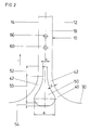
- the basic structure of the coolable blade 1 according to the invention results can be seen in particular from FIGS. 1 and 2.
- the blade 1 has an airfoil 10 and a blade root 30, with the transition area between the airfoil 10 and the blade root 30 a blade root 40 is formed.
- the airfoil 10 consists of a suction side wall 12 and a pressure side Wall 14 constructed, each opposite a front edge 16 and a trailing edge 18 are connected to each other. Between the suction side Wall 12 and the pressure side wall 14 thus creates a cavity 20, which is continuously in the radial direction r from the blade 10 into the blade root 30 extends into it.
- the cavity 20 is flowed through by a cooling medium K, which over the area of the blade root 30, meandering in the area of the blade 10 deflected several times and through discharge openings in the form of through holes 60 and a blowout slot 50 is blown out.
- a cooling medium K is usually used air that comes from the compressor stage, not shown here is branched off.
- the blade root 40 has a concave curve in the area of the rear edge 18 Contour course on, so that a continuous transition without a jump in curvature is realized by the blade 10 in the blade root 30.
- the blowout slot 50 is arranged, which is continuously between an entry level 56 on the cavity 20 and an exit level 58 extends at the rear edge 18.
- the area of the blade root 40 it has a cross-sectional shape in the exit plane 58 which corresponds to the outer contour the blade 40 follows so far that wall sections on both sides 42 with approximately constant wall thickness d.
- the blow-out slot 50 merges upwards into a radial section 52 which has a constant width b in the manner of a longitudinal slot.
- the width is b chosen such that a constant wall thickness is also present in this radial section 52 d remains.
- the blowout slot 50 has the basic shape of an isosceles Triangles with concave legs.
- the blowout slot 50 thus covers the entire area of the blade root 40 and protrudes into the two adjacent areas of the airfoil 10 and the Blade root 30 into it.
- the cross-sectional shape in connection with the chosen one Contour course of the blade root 40 prevents notch stresses in it critical area and at the same time enables effective cooling.
- 3 and 4 are two variants of a possible cross-sectional profile between the entrance plane 56 on the cavity 20 and the exit plane 58 on the Trailing edge 18 indicated.
- the first variant according to FIG. 3 has a continuous, constant cross-sectional shape on. It enables a high throughput of cooling medium, so that the cooling effect on the rear edge 18 can be adjusted to a maximum.
- the variant shown in Fig. 4 has one in the flow direction of the cooling medium K continuously changing cross section.
- At entry level 56 is a continuous longitudinal slot of constant width available, which extends to the exit plane 58 expanded and reached there the pear-shaped cross-sectional shape.
- This Variant has the advantage of lower cooling medium K consumption.
- Hot gas flow occurs when the blow-out slot 50 is between the entry level 56 and the exit plane 58 extends radially as shown in FIG. 1 is indicated.
- the cooling concept described above is suitable for applications in control and blades equally well.
- the outer contour of the blade root approximate course of the cross-sectional geometry of the blow-out slot enables the effective reduction of material stress in particular critical area of the trailing edge, increasing the lifespan of the bucket can be increased significantly overall.
Landscapes
- Engineering & Computer Science (AREA)
- Mechanical Engineering (AREA)
- General Engineering & Computer Science (AREA)
- Turbine Rotor Nozzle Sealing (AREA)
Abstract
Description
- Fig. 1
- Schaufel in Schnittdarstellung;
- Fig. 2
- Schaufel gemäß Fig. 1 in einer Ansicht von links, vergrößerte Teilansicht;
- Fig. 3
- Ausblasschlitz in perspektivischer Darstellung;
- Fig. 4
- Ausblasschlitz in perspektivischer Darstellung, Variante zu dem Ausblasschlitz gemäß Fig. 3.
- 1
- Schaufel
- 10
- Schaufelblatt
- 12
- saugseitige Wand
- 14
- druckseitige Wand
- 16
- Vorderkante
- 18
- Hinterkante
- 20
- Hohlraum, Kühlkanal
- 30
- Schaufelfuß
- 40
- Schaufelwurzel
- 42
- Wandabschnitt
- 50
- Ausblasschlitz
- 52
- Radialabschnitt
- 53
- Radialabschnitt
- 54
- Radialabschnitt
- 56
- Eintrittsebene
- 58
- Austrittsebene
- 60
- Bohrung
- b
- Schlitzbreite
- B
- Schlitzbreite
- d
- Wanddicke
- r
- radiale Richtung
- K
- Kühlmedium
Claims (8)
- Kühlbare Schaufel für eine Gasturbine oder dergleichen, mitdadurch gekennzeichnet, dass zumindest im Bereich der Hinterkante (18) die Schaufelwurzel (40) einen konkav gekrümmten Konturverlauf aufweist und dass eine der Ausblasöffnungen als Ausblasschlitz (50) an der Schaufelwurzel (40) angeordnet ist, der sich in der Austrittsebene (58) der Hinterkante (18) in radialer Richtung (r) zumindest über den gesamten Bereich der Schaufelwurzel (40) erstreckt und dessen Querschnittsform zumindest in der Austrittsebene (58) dem Konturverlauf der Schaufelwurzel (40) soweit folgt, dass Wandabschnitte (42) mit angenähert konstanter Wanddicke (d) entstehen.einem Schaufelblatt, das aus einer saugseitigen Wand und einer druckseitigen Wand aufgebaut ist, welche unter Bildung eines Hohlraumes über eine Vorderkante und eine Hinterkante verbunden sind,einem Schaufelfuß,einer Schaufelwurzel als Übergangsbereich zwischen dem Schaufelblatt und dem Schaufelfuß,wenigstens einem Kühlkanal, der im Hohlraum integriert und von einem Kühlmedium durchströmbar ist, sowieAusblasöffnungen für das Kühlmedium, die ausgehend von einer Eintritts ebene am Hohlraum durchgehend zu einer Austrittsebene im Bereich der Hinterkante angeordnet sind,
- Schaufel nach Anspruch 1,
dadurch gekennzeichnet, dass der Ausblasschlitz (50) einen dem Schaufelblatt (10) zugeordneten Radialabschnitt (52) konstanter Breite (b) aufweist und in einen der Schaufelwurzel (40) zugeordneten Radialabschnitt (53) kontinuierlich übergeht, der die Grundform eines gleichschenkligen Dreiecks mit konkavgekrümmten Schenkeln besitzt. - Schaufel nach Anspruch 1 oder 2,
dadurch gekennzeichnet, dass der Ausblasschlitz (50) einen birnenförmigen Querschnitt aufweist. - Schaufel nach einem der Ansprüche 1 bis 3,
dadurch gekennzeichnet, dass der Ausblasschlitz (50) eine in Strömungsrichtung des Kühlmediums (K) konstante Querschnittsform aufweist. - Schaufel nach einem der Ansprüche 1 bis 3,
dadurch gekennzeichnet, dass der Ausblasschlitz (50) in der Eintrittsebene (56) die Form eines radial verlaufenden Längsschlitzes besitzt und in Strömungsrichtung des Kühlmediums (K) kontinuierlich in die Querschnittsform in der Austrittsebene (58) übergeht. - Schaufel nach einem der vorhergehenden Ansprüche,
dadurch gekennzeichnet, dass der Ausblasschlitz (50) einen Radialabschnitt (54) aufweist, der dem Schaufelfuß (30) zugeordnet ist. - Schaufel nach einem der vorhergehenden Ansprüche,
dadurch gekennzeichnet, dass der Ausblasschlitz (50) in Strömungsrichtung des Kühlmediums (K) radial ansteigend verläuft. - Schaufel nach einem der vorhergehenden Ansprüche,
dadurch gekennzeichnet, dass sich der Ausblasschlitz (50) in radialer Richtung (r) im Wesentlichen durchgehend über die Hinterkante (18) erstreckt.
Applications Claiming Priority (2)
| Application Number | Priority Date | Filing Date | Title |
|---|---|---|---|
| DE19860788A DE19860788A1 (de) | 1998-12-30 | 1998-12-30 | Kühlbare Schaufel für eine Gasturbine |
| DE19860788 | 1998-12-30 |
Publications (3)
| Publication Number | Publication Date |
|---|---|
| EP1016773A2 true EP1016773A2 (de) | 2000-07-05 |
| EP1016773A3 EP1016773A3 (de) | 2003-12-03 |
| EP1016773B1 EP1016773B1 (de) | 2005-08-03 |
Family
ID=7893161
Family Applications (1)
| Application Number | Title | Priority Date | Filing Date |
|---|---|---|---|
| EP99811183A Expired - Lifetime EP1016773B1 (de) | 1998-12-30 | 1999-12-21 | Kühlbare Schaufel für eine Gasturbine |
Country Status (2)
| Country | Link |
|---|---|
| EP (1) | EP1016773B1 (de) |
| DE (2) | DE19860788A1 (de) |
Cited By (4)
| Publication number | Priority date | Publication date | Assignee | Title |
|---|---|---|---|---|
| FR2864990A1 (fr) * | 2004-01-14 | 2005-07-15 | Snecma Moteurs | Perfectionnements apportes aux fentes d'evacuation de l'air de refroidissement d'aubes de turbine haute-pression |
| US10260355B2 (en) | 2016-03-07 | 2019-04-16 | Honeywell International Inc. | Diverging-converging cooling passage for a turbine blade |
| EP3677750A1 (de) * | 2019-01-04 | 2020-07-08 | United Technologies Corporation | Gasturbinenmotorkomponente mit einem austrittsschlitz an der abströmkante |
| US20230151737A1 (en) * | 2021-11-18 | 2023-05-18 | Raytheon Technologies Corporation | Airfoil with axial cooling slot having diverging ramp |
Families Citing this family (3)
| Publication number | Priority date | Publication date | Assignee | Title |
|---|---|---|---|---|
| DE19921644B4 (de) | 1999-05-10 | 2012-01-05 | Alstom | Kühlbare Schaufel für eine Gasturbine |
| AU2002342500A1 (en) | 2001-12-10 | 2003-07-09 | Alstom Technology Ltd | Thermally loaded component |
| WO2003052240A2 (de) | 2001-12-14 | 2003-06-26 | Alstom Technology Ltd | Gasturbinenanordnung |
Citations (1)
| Publication number | Priority date | Publication date | Assignee | Title |
|---|---|---|---|---|
| US5498133A (en) | 1995-06-06 | 1996-03-12 | General Electric Company | Pressure regulated film cooling |
Family Cites Families (5)
| Publication number | Priority date | Publication date | Assignee | Title |
|---|---|---|---|---|
| GB1605180A (en) * | 1974-05-16 | 1983-01-26 | Lls Royce Ltd | Method for manufacturing a blade for a gas turbine engine |
| US3966357A (en) * | 1974-09-25 | 1976-06-29 | General Electric Company | Blade baffle damper |
| US4236870A (en) * | 1977-12-27 | 1980-12-02 | United Technologies Corporation | Turbine blade |
| GB2189553B (en) * | 1986-04-25 | 1990-05-23 | Rolls Royce | Cooled vane |
| JP3316418B2 (ja) * | 1997-06-12 | 2002-08-19 | 三菱重工業株式会社 | ガスタービン冷却動翼 |
-
1998
- 1998-12-30 DE DE19860788A patent/DE19860788A1/de not_active Withdrawn
-
1999
- 1999-12-21 EP EP99811183A patent/EP1016773B1/de not_active Expired - Lifetime
- 1999-12-21 DE DE59912356T patent/DE59912356D1/de not_active Expired - Lifetime
Patent Citations (1)
| Publication number | Priority date | Publication date | Assignee | Title |
|---|---|---|---|---|
| US5498133A (en) | 1995-06-06 | 1996-03-12 | General Electric Company | Pressure regulated film cooling |
Cited By (9)
| Publication number | Priority date | Publication date | Assignee | Title |
|---|---|---|---|---|
| FR2864990A1 (fr) * | 2004-01-14 | 2005-07-15 | Snecma Moteurs | Perfectionnements apportes aux fentes d'evacuation de l'air de refroidissement d'aubes de turbine haute-pression |
| EP1555390A1 (de) * | 2004-01-14 | 2005-07-20 | Snecma Moteurs | Kühlluftauslass-Schlitze von Turbinenschaufeln |
| US7278827B2 (en) | 2004-01-14 | 2007-10-09 | Snecma Moteurs | Cooling air evacuation slots of turbine blades |
| US10260355B2 (en) | 2016-03-07 | 2019-04-16 | Honeywell International Inc. | Diverging-converging cooling passage for a turbine blade |
| EP3677750A1 (de) * | 2019-01-04 | 2020-07-08 | United Technologies Corporation | Gasturbinenmotorkomponente mit einem austrittsschlitz an der abströmkante |
| US10815792B2 (en) | 2019-01-04 | 2020-10-27 | Raytheon Technologies Corporation | Gas turbine engine component with a cooling circuit having a flared base |
| US20230151737A1 (en) * | 2021-11-18 | 2023-05-18 | Raytheon Technologies Corporation | Airfoil with axial cooling slot having diverging ramp |
| EP4183981A1 (de) * | 2021-11-18 | 2023-05-24 | Raytheon Technologies Corporation | Schaufel, gasturbinentriebwerk und feingusskern |
| US12158083B2 (en) | 2021-11-18 | 2024-12-03 | Rtx Corporation | Airfoil with axial cooling slot having diverging ramp |
Also Published As
| Publication number | Publication date |
|---|---|
| EP1016773B1 (de) | 2005-08-03 |
| DE59912356D1 (de) | 2005-09-08 |
| DE19860788A1 (de) | 2000-07-06 |
| EP1016773A3 (de) | 2003-12-03 |
Similar Documents
| Publication | Publication Date | Title |
|---|---|---|
| EP3762587B1 (de) | Schaufelblatt für eine turbinenschaufel | |
| EP1614859B1 (de) | Filmgekühlte Turbinenschaufel | |
| DE69507451T2 (de) | Turbinenschaufelkühlung | |
| EP1267039B1 (de) | Kühlkonstruktion für Schaufelblatthinterkante | |
| DE69924953T2 (de) | Schaufel eines Gasturbinentriebwerks | |
| EP2828484B1 (de) | Turbinenschaufel | |
| DE69822100T2 (de) | Turbinenschaufel | |
| DE69932966T2 (de) | Leitschaufelanordnung für eine Turbomaschine | |
| DE602005006362T2 (de) | Vielgestaltige Filmkühlungsbohrungen | |
| EP1907671B1 (de) | Gasturbinenschaufelkranz | |
| DE60017437T2 (de) | Rippen zur erhöhung der wärmeübertragung einer mittels kühlluft innengekühlten turbinenschaufel | |
| EP1512489B1 (de) | Schaufel einer Turbine | |
| EP1789654B1 (de) | Strömungsmaschinenschaufel mit fluidisch gekühltem deckband | |
| WO2007012590A1 (de) | Gekühlte turbinenschaufel für eine gasturbine und verwendung einer solchen turbinenschaufel | |
| EP0825332B1 (de) | Kühlbare Schaufel | |
| EP1907670B1 (de) | Gekühlte turbinenschaufel für eine gasturbine und verwendung einer solchen turbinenschaufel | |
| EP1834066A1 (de) | Turbinenschaufel für eine gasturbine, verwendung einer turbinenschaufel sowie verfahren zum kühlen einer turbinenschaufel | |
| EP1126136B1 (de) | Turbinenschaufel mit luftgekühltem Deckbandelement | |
| DE60220556T2 (de) | Kühlung der Übergangsradien einer Statorschaufel | |
| WO2005019621A1 (de) | Diffusor zwischen verdichter und brennkammer einer gasturbine angeordnet | |
| DE69925447T2 (de) | Kühlbare Schaufelblätter | |
| DE112019000921B4 (de) | Turbinenrotorschaufel und gasturbine | |
| EP1016773B1 (de) | Kühlbare Schaufel für eine Gasturbine | |
| EP1207269B1 (de) | Gasturbinenschaufel | |
| EP0992655B1 (de) | Kühlkanal für ein thermisch hochbelastetes Bauteil |
Legal Events
| Date | Code | Title | Description |
|---|---|---|---|
| PUAI | Public reference made under article 153(3) epc to a published international application that has entered the european phase |
Free format text: ORIGINAL CODE: 0009012 |
|
| AK | Designated contracting states |
Kind code of ref document: A2 Designated state(s): AT BE CH CY DE DK ES FI FR GB GR IE IT LI LU MC NL PT SE |
|
| AX | Request for extension of the european patent |
Free format text: AL;LT;LV;MK;RO;SI |
|
| RAP1 | Party data changed (applicant data changed or rights of an application transferred) |
Owner name: ALSTOM |
|
| RAP1 | Party data changed (applicant data changed or rights of an application transferred) |
Owner name: ALSTOM (SWITZERLAND) LTD |
|
| PUAL | Search report despatched |
Free format text: ORIGINAL CODE: 0009013 |
|
| AK | Designated contracting states |
Kind code of ref document: A3 Designated state(s): AT BE CH CY DE DK ES FI FR GB GR IE IT LI LU MC NL PT SE |
|
| AX | Request for extension of the european patent |
Extension state: AL LT LV MK RO SI |
|
| RAP1 | Party data changed (applicant data changed or rights of an application transferred) |
Owner name: ALSTOM TECHNOLOGY LTD |
|
| 17P | Request for examination filed |
Effective date: 20040522 |
|
| 17Q | First examination report despatched |
Effective date: 20040624 |
|
| AKX | Designation fees paid |
Designated state(s): DE GB |
|
| GRAP | Despatch of communication of intention to grant a patent |
Free format text: ORIGINAL CODE: EPIDOSNIGR1 |
|
| GRAS | Grant fee paid |
Free format text: ORIGINAL CODE: EPIDOSNIGR3 |
|
| GRAA | (expected) grant |
Free format text: ORIGINAL CODE: 0009210 |
|
| AK | Designated contracting states |
Kind code of ref document: B1 Designated state(s): DE GB |
|
| REG | Reference to a national code |
Ref country code: GB Ref legal event code: FG4D Free format text: NOT ENGLISH |
|
| REF | Corresponds to: |
Ref document number: 59912356 Country of ref document: DE Date of ref document: 20050908 Kind code of ref document: P |
|
| GBT | Gb: translation of ep patent filed (gb section 77(6)(a)/1977) |
Effective date: 20051003 |
|
| PLBE | No opposition filed within time limit |
Free format text: ORIGINAL CODE: 0009261 |
|
| STAA | Information on the status of an ep patent application or granted ep patent |
Free format text: STATUS: NO OPPOSITION FILED WITHIN TIME LIMIT |
|
| 26N | No opposition filed |
Effective date: 20060504 |
|
| REG | Reference to a national code |
Ref country code: DE Ref legal event code: R082 Ref document number: 59912356 Country of ref document: DE Representative=s name: ROESLER, UWE, DIPL.-PHYS.UNIV., DE Ref country code: DE Ref legal event code: R081 Ref document number: 59912356 Country of ref document: DE Owner name: ANSALDO ENERGIA IP UK LIMITED, GB Free format text: FORMER OWNER: ALSTOM TECHNOLOGY LTD., BADEN, CH Ref country code: DE Ref legal event code: R081 Ref document number: 59912356 Country of ref document: DE Owner name: GENERAL ELECTRIC TECHNOLOGY GMBH, CH Free format text: FORMER OWNER: ALSTOM TECHNOLOGY LTD., BADEN, CH |
|
| PGFP | Annual fee paid to national office [announced via postgrant information from national office to epo] |
Ref country code: GB Payment date: 20161222 Year of fee payment: 18 Ref country code: DE Payment date: 20161213 Year of fee payment: 18 |
|
| REG | Reference to a national code |
Ref country code: DE Ref legal event code: R082 Ref document number: 59912356 Country of ref document: DE Representative=s name: ROESLER, UWE, DIPL.-PHYS.UNIV., DE Ref country code: DE Ref legal event code: R081 Ref document number: 59912356 Country of ref document: DE Owner name: ANSALDO ENERGIA IP UK LIMITED, GB Free format text: FORMER OWNER: GENERAL ELECTRIC TECHNOLOGY GMBH, BADEN, CH |
|
| REG | Reference to a national code |
Ref country code: GB Ref legal event code: 732E Free format text: REGISTERED BETWEEN 20170824 AND 20170830 |
|
| REG | Reference to a national code |
Ref country code: DE Ref legal event code: R119 Ref document number: 59912356 Country of ref document: DE |
|
| GBPC | Gb: european patent ceased through non-payment of renewal fee |
Effective date: 20171221 |
|
| PG25 | Lapsed in a contracting state [announced via postgrant information from national office to epo] |
Ref country code: DE Free format text: LAPSE BECAUSE OF NON-PAYMENT OF DUE FEES Effective date: 20180703 |
|
| PG25 | Lapsed in a contracting state [announced via postgrant information from national office to epo] |
Ref country code: GB Free format text: LAPSE BECAUSE OF NON-PAYMENT OF DUE FEES Effective date: 20171221 |