EP1016781A2 - Kalorische Maschine - Google Patents
Kalorische Maschine Download PDFInfo
- Publication number
- EP1016781A2 EP1016781A2 EP99125201A EP99125201A EP1016781A2 EP 1016781 A2 EP1016781 A2 EP 1016781A2 EP 99125201 A EP99125201 A EP 99125201A EP 99125201 A EP99125201 A EP 99125201A EP 1016781 A2 EP1016781 A2 EP 1016781A2
- Authority
- EP
- European Patent Office
- Prior art keywords
- working
- caloric
- cylinder
- piston
- valve
- Prior art date
- Legal status (The legal status is an assumption and is not a legal conclusion. Google has not performed a legal analysis and makes no representation as to the accuracy of the status listed.)
- Granted
Links
Images

Classifications
-
- F—MECHANICAL ENGINEERING; LIGHTING; HEATING; WEAPONS; BLASTING
- F02—COMBUSTION ENGINES; HOT-GAS OR COMBUSTION-PRODUCT ENGINE PLANTS
- F02G—HOT GAS OR COMBUSTION-PRODUCT POSITIVE-DISPLACEMENT ENGINE PLANTS; USE OF WASTE HEAT OF COMBUSTION ENGINES; NOT OTHERWISE PROVIDED FOR
- F02G1/00—Hot gas positive-displacement engine plants
- F02G1/04—Hot gas positive-displacement engine plants of closed-cycle type
- F02G1/043—Hot gas positive-displacement engine plants of closed-cycle type the engine being operated by expansion and contraction of a mass of working gas which is heated and cooled in one of a plurality of constantly communicating expansible chambers, e.g. Stirling cycle type engines
- F02G1/044—Hot gas positive-displacement engine plants of closed-cycle type the engine being operated by expansion and contraction of a mass of working gas which is heated and cooled in one of a plurality of constantly communicating expansible chambers, e.g. Stirling cycle type engines having at least two working members, e.g. pistons, delivering power output
Definitions
- the present invention relates to a caloric machine, operated with a working medium in two work cycles becomes.
- the invention also relates to a motor unit for Provision of mechanical energy.
- thermal engines are called caloric machines understood, taking advantage of the thermodynamic laws of thermal energy in mechanical Energy is converted. This becomes a working medium Thermal energy supplied, which is the volume expansion of the Working medium causes which to perform mechanical Work can be used. In a subsequent one Work cycle is extracted from the working medium thermal energy, which results in a reduction in volume. With caloric Machines run these two work cycles in a cycle off, so that the machine continuously mechanical energy can provide.
- a caloric machine is said to be available be made using the simplest mechanical Components can continuously release mechanical energy. It is also particularly desirable to use this machine in this way design that linear forces can be delivered. Finally it is an object of the present invention to provide a motor unit using an appropriate caloric Specify machine.
- This caloric machine has the advantage that the Working and loading pistons are arranged so that they have linear forces Deliver directly to a linear power transmission block can without additional gear elements are required. In this way, lateral forces are avoided. So that can also the mostly high friction losses with conventional bodies be significantly reduced. Due to the symmetrical Can link two working pistons and two loading pistons from the machine according to the invention in both work cycles mechanical energy are released, so that each provided amount of energy relatively evenly over the Time is distributed. To overcome the remaining Dead spots require only a small amount of energy This means, for example, that flywheels are small can be held.
- the structure according to the invention offers also the advantage that the machine is self-starting, whereby conventional starter aids can be saved.
- caloric machine is based on the strictly linear principle deviated and instead of the connecting rods there are connecting rods to use the working and loading pistons via pegs connect with a crankshaft.
- the two pairs of pistons attack 180 ° out of phase on the crankshaft.
- the caloric machine have the heating cavity and the Cooling cavity each a constant volume, the Volume of the two cavities can also be identical.
- a modified embodiment is characterized in that that the linear force transmission block one on guide columns slidably mounted frame, which is on a first Side of the first working piston and the first loading piston and on a second side opposite the first coupled the second working piston and the second loading piston is.
- This embodiment enables one in particular simple mechanical structure, in which the first working piston and the first loading piston on the one hand and the second Working piston and the second loading piston on the other hand in parallel are arranged to each other, each with the working piston and the charge pistons are moved in opposite directions to each other and introduce the forces linearly into the linear force transmission block or received by it.
- valves can also be controlled by electrical signals and For example, be designed as a solenoid valve or as hydraulic valves be formed. This is for example then expedient if high precision with regard to the Switching times of the valves and a high switching speed are desired.
- a further developed embodiment is a linear force transmission block with a rack attached to it characterized, with two counter-acting freewheel gears engage the rack and the alternating Linear movement in an associated gear wheel implement constant rotary motion.
- This embodiment can be used to advantage if available provided linear force can be converted into a rotary movement should, as is desirable for example in motor vehicles is.
- heating cavity is designed as a solar collector is.
- the heat is then supplied directly by sunlight.
- the Pressure and volume conditions in the caloric machine be chosen according to the laws of thermodynamics so that the working medium expands in the cooling cavity, which results in cooling.
- the provided thereby "Cold source” can be used for cooling or air conditioning the surrounding area.
- a motor unit in which at least two caloric machines of the invention Type are interconnected, preferably four caloric machines, each 90 ° out of phase be interconnected.
- caloric machines according to the invention can be increase overall performance and the running characteristics of a improve the corresponding motor unit. Because the individual Working machines out of phase results in a more uniform Distribution of the mechanical energy provided, because the dead centers are also 90 ° out of phase.
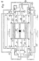
- the caloric machine has a first working piston 1, which runs in a first cylinder 2.
- first Working piston 1 is attached to a first push rod 3 which essentially in a straight line to one central arranged linear power transmission block 4 extends and on a first side 5 of this linear force transmission block 4 is attached.
- a first charging piston 7 is provided, which runs in a first loading cylinder 8 and a second push rod 9 also on the first side 5 of the linear force transmission block 4 is coupled.
- the second push rod 9 runs essentially parallel to the first push rod 3.
- the working volume of the first working cylinder 2 is designed to be significantly larger than the work volume of the first loading cylinder 8.
- a second working piston 11 is provided, which again runs in a second cylinder 12 and over a third push rod 13 to the linear power transmission block 4 is coupled.
- the third push rod 13 is on one attached second side 14 of the linear force transmission block 4, the second side 14 of the first side 5 in is essentially parallel.
- a second charge piston 16 is also provided, who works in a second loading cylinder 17 and over a fourth push rod 18 also with the second side 14 of the linear force transmission block 4 is connected.
- the Working volume of the second working cylinder 12 corresponds to essentially the working volume of the first working cylinder 2, while the working volume of the second loading cylinder 17 in essentially the working volume of the first loading cylinder 8 corresponds to and smaller than the working volume of the working cylinder is.
- the caloric machine has a heating cavity 20 and a cooling cavity 21, which is preferably a have constant volume, especially the heating cavity 20 and the cooling cavity 21 an almost identical Have volume.
- a working medium whose flow direction is indicated by individual arrows.
- a working medium come preferably substances with a relatively low boiling point, such as water, alcohol, ether or helium to be used, wherein the special substance taking into account the respective Select the application and the working temperatures used is.
- the working medium is continuously in the heating cavity Supplied heat. This will be an external heat source used. For heating, for example, heating materials be burned or in the respective application Waste heat available serve as a heat source.
- heating cavity To lay out solar panel or put it in suitable other Way the thermal energy provided by solar radiation feed.
- the formation of the heating cavity as Solar panel has proven to be particularly simple and useful proved that on the one hand the working medium in easier Way through the solar panels and on the other hand the solar energy used is available free of charge stands.
- first work cycle of the caloric Machine described in detail.
- the first work cycle flows through a first hot medium line 25 and opened first working valve 26 the heated working medium in the first working cylinder 2, whereby the first Piston 1 is driven out while doing the first Push rod 3 a linear force on the linear force transmission block 4 exercises.
- the linear power transmission block 4 makes a linear movement from left to right, as made clear by the drawn arrow is.
- the second push rod 9 By coupling via the second push rod 9 also the first charging piston 7 from the first charging cylinder 8 moved out, so that cold working medium over an open first charging valve 27 and a first charging line 28 in the can flow first charging cylinder 8.
- the available standing force depends on the amount of heat supplied, since this is about the expansion of the working fluid in the heating cavity and thus about the volume of the first Working cylinder 2 is pressed, decides.
- the force provided by the first working piston 1 is also via the linear power transmission block 4 to the third push rod 13 and the fourth push rod 18 transmitted.
- that located in the second loading cylinder 17 cooled working medium expelled from the second charging piston 16 and flows in via a first return line 29 and opened second charging valve 30 back into the heating cavity 20, in which it is reheated and a volume expansion experiences.
- It will also be relatively warm Working medium, which is in the second cylinder 12th is driven out by the second piston 11, so that it has a second return line 31 and an open second working valve 32 flows back into the cooling cavity 21.
- the relatively warm working medium is in the cooling cavity 21 Deprived of heat.
- the linear force transmission block 4 has guide sleeves 40 mounted on pillars 41 so that a low-friction linear motion can be performed.
- FIG. 2 With reference to Fig. 2, the flow conditions in the caloric machine during the second Work cycle explained.
- the position of the individual pistons in the cylinders shown in Fig. 2 correspond to that 1, but during an opposite movement, which in turn is indicated by an arrow in the area of the linear force transmission block is shown.
- This shown movement from right to left flows hot Working medium from the heating cavity 20 via a second Hot medium line 45 through the now open third Working valve 33 in the second working cylinder 12.
- Das in the second working cylinder 12 flowing under pressure Working medium causes the second working piston to move 11, this movement over the third push rod 13 on the second side 14 of the linear force transmission block 4 is directed.
- FIGS. 1 and 2 causes the linear force transmission block 4 in each case essentially switching at the reversal points of the linear movement of the control valves mentioned, so that the maintenance force required to move alternately from first working piston and provided by the second working piston becomes. Due to the strictly linear power transmission no crankshafts and connecting rods in this embodiment required, as in conventional internal combustion engines the case is. The material stresses are therefore less, which in connection with the relatively low working speeds to a long service life of the machine and leads to remarkable smoothness. Modified embodiments the invention can also the crankshaft principle use.
- the mechanical energy provided To use drive purposes is in the illustrated embodiment on the linear power transmission block 4, a rack 50 attached, in which a gear 51 engages. Because of the two-stroke method of operation described caloric machine there is an alternating linear movement the rack 50, which rotates the gear 51 with a changing direction.
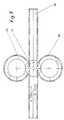
- Fig. 3 shows a simplified schematic diagram of a Possibility of this rotary movement with changing direction to convert it into a rotational movement with the same sense of direction.
- the rack 50 stands in this case with a first freewheel gear 52 and a second freewheel gear 53 engaged, each in turn in a central gear 54 intervene.
- the freewheel gear 52, 53 are arranged that depending on the direction of movement of the rack 50 always only a freewheel transmission transmits power to that performs central gear 54 so that it rotates is shifted with a constant sense of direction. On an output shaft can then be attached to the central gear 54 his.
- the caloric machine according to the invention can also be used with any other types of gears. It is the same possible to control the valves not on mechanical but in an electrical, hydraulic or other way to make.
- the caloric machine explained can be used as compact unit can be built, so that the interconnection several such units possible without difficulty is. In this way, for example, motors build up that combine several of these units.
- crankshaft principle Replace the crankshaft principle, with all pistons using connecting rods be coupled to a common crankshaft.
Landscapes
- Engineering & Computer Science (AREA)
- Chemical & Material Sciences (AREA)
- Combustion & Propulsion (AREA)
- Mechanical Engineering (AREA)
- General Engineering & Computer Science (AREA)
- Hydraulic Motors (AREA)
- Actuator (AREA)
- Engine Equipment That Uses Special Cycles (AREA)
- Yarns And Mechanical Finishing Of Yarns Or Ropes (AREA)
- Devices That Are Associated With Refrigeration Equipment (AREA)
- Control And Other Processes For Unpacking Of Materials (AREA)
- Saccharide Compounds (AREA)
Abstract
Description
- Fig. 1
- ein Prinzipschaltbild einer kalorischen Maschine, dargestellt während eines ersten Arbeitstaktes;
- Fig. 2
- das Prinzipschaltbild der kalorischen Maschine, dargestellt während eines zweiten Arbeitstaktes;
- Fig. 3
- eine vereinfachte Darstellung eines Zahnstangengetriebes der kalorischen Maschine.
Claims (9)
- Kalorische Maschine, die mit einem Arbeitsmedium in zwei Arbeitstakten betrieben wird, umfassend:wobei während des ersten Arbeitstaktes das erwärmte Arbeitsmedium aus dem Erwärmungshohlraum (20) über ein erstes Arbeitsventil (26) in den ersten Arbeitszylinder (2) und aus dem zweiten Arbeitszylinder (12) über ein zweites Arbeitsventil (32) in den Kühlhohlraum (21) strömt, während das abgekühlte Arbeitsmedium aus dem Kühlhohlraum (21) über ein erstes Ladeventil (28) in den ersten Ladezylinder (8) und aus dem zweiten Ladezylinder (17) über ein zweites Ladeventil (30) in den Erwärmungshohlraum (20) strömt; und wobei während des zweiten Arbeitstaktes das erwärmte Arbeitsmedium aus dem Erwärmungshohlraum (20) über ein drittes Arbeitsventil (33) in den zweiten Arbeitszylinder (12) und aus dem ersten Arbeitszylinder (2) über ein viertes Arbeitsventil (35) in den Kühlhohlraum (21) strömt, während das abgekühlte Arbeitsmedium aus dem Kühlhohlraum (21) über ein drittes Ladeventil (34) in den zweiten Ladezylinder (17) und aus dem ersten Ladezylinder (8) über ein viertes Ladeventil (36) in den Erwärmungshohlraum (20) strömt; und wobei während des ersten Arbeitstaktes das dritte und vierte Arbeitsventil (33, 35) und das dritte und vierte Ladeventil (34, 36) geschlossen sind und während des zweiten Arbeitstaktes das erste und zweite Arbeitsventil (26, 32) und das erste und zweite Ladeventil (27, 30) geschlossen sind.einen ersten Arbeitskolben (1), der in einem ersten Arbeitszylinder (2) läuft und über eine erste Schubstange (3) an einen Linearkraftübertragungsblock (4) gekoppelt ist, welcher in der Bewegungsrichtung des ersten Arbeitskolbens verschiebbar ist;einen ersten Ladekolben (7), der in einem ersten Ladezylinder (8) läuft und über eine parallel zur ersten Schubstange (3) angeordnete zweite Schubstange (9) an den Linearkraftübertragungsblock (4) gekoppelt ist;einen zweiten Arbeitskolben (11), der in einem zweiten Arbeitszylinder (12) in zum ersten Arbeitskolben (1) entgegengesetzter Arbeitsrichtung läuft und über eine dritte Schubstange (13) an den Linearkraftübertragungsblock (4) gekoppelt ist;einen zweiten Ladekolben (16), der in einem zweiten Ladezylinder (17) in zum ersten Ladekolben (7) entgegengesetzter Arbeitsrichtung läuft und über eine parallel zur dritten Schubstange (13) angeordnete vierte Schubstange (18) an den Linearkraftübertragungsblock (4) gekoppelt ist;einen Erwärmungshohlraum (20), in welchem dem Arbeitsmedium Wärme zugeführt wird; undeinen Kühlhohlraum (21), in welchem dem Arbeitsmedium Wärme entzogen wird;
- Kalorische Maschine nach Anspruch 1 , dadurch gekennzeichnet, daß Erwärmungshohlraum (20) und Kühlhohlraum (21) jeweils ein konstantes Volumen besitzen.
- Kalorische Maschine nach Anspruch 1 oder 2, dadurch gekennzeichnet, daß der Linearkraftübertragungsblock (4) ein durch Führungssäulen (41) und Führungshülsen (40) verschiebbar gelagertes Gestell ist, welches auf einer ersten Seite (5) an den ersten Arbeitskolben (1) und den ersten Ladekolben (7) und an einer zweiten, der ersten gegenüberliegenden Seite (14) an den zweiten Arbeitskolben (11) und den zweiten Ladekolben (16) gekoppelt ist.
- Kalorische Maschine nach einem der Ansprüche 1 bis 3, dadurch gekennzeichnet, daß alle Ventile (26, 27, 30, 32-36) mechanisch vom Linearkraftübertragungsblock (4) betätigt werden.
- Kalorische Maschine nach einem der Ansprüche 1 bis 4, dadurch gekennzeichnet, daß am Linearkraftübertragungsblock (4) eine Zahnstange (50) angeordnet ist, in die zwei gegenläufig wirkende Freilaufgetriebe (52, 53) eingreifen, die ihrerseits mit einem Zahnrad (54) in Eingriff stehen, so daß die alternierende Linearbewegung in eine kontinuierliche Drehbewegung umgesetzt wird.
- Kalorische Maschine nach einem der Ansprüche 1 bis 4, dadurch gekennzeichnet, daß am Linearkraftübertragungsblock eine langgestreckte elektrische Erregerwicklung angeordnet ist, die in umgebenden elektrischen Spulen linear bewegt wird, so daß in diesen Spulen eine elektrische Spannung induziert wird.
- Kalorische Maschine nach einem der Ansprüche 1 bis 6, dadurch gekennzeichnet, daß der Erwärmungshohlraum (20) als Sonnenkollektor ausgebildet ist.
- Motoreinheit zur Bereitstellung mechanischer Energie, dadurch gekennzeichnet, daß mindestens zwei kalorische Maschinen nach einem der Ansprüche 1 bis 7 zusammengeschaltet sind.
- Motoreinheit nach Anspruch 8, dadurch gekennzeichnet, daß vier kalorische Maschinen, die jeweils um 90° phasenversetzt arbeiten, zusammengeschaltet sind.
Applications Claiming Priority (2)
| Application Number | Priority Date | Filing Date | Title |
|---|---|---|---|
| DE19860522 | 1998-12-29 | ||
| DE19860522A DE19860522C1 (de) | 1998-12-29 | 1998-12-29 | Kalorische Maschine |
Publications (3)
| Publication Number | Publication Date |
|---|---|
| EP1016781A2 true EP1016781A2 (de) | 2000-07-05 |
| EP1016781A3 EP1016781A3 (de) | 2001-06-27 |
| EP1016781B1 EP1016781B1 (de) | 2005-02-23 |
Family
ID=7892981
Family Applications (1)
| Application Number | Title | Priority Date | Filing Date |
|---|---|---|---|
| EP99125201A Expired - Lifetime EP1016781B1 (de) | 1998-12-29 | 1999-12-17 | Kalorische Maschine |
Country Status (6)
| Country | Link |
|---|---|
| EP (1) | EP1016781B1 (de) |
| AT (1) | ATE289656T1 (de) |
| CY (1) | CY1105562T1 (de) |
| DE (2) | DE19860522C1 (de) |
| ES (1) | ES2238808T3 (de) |
| PT (1) | PT1016781E (de) |
Cited By (2)
| Publication number | Priority date | Publication date | Assignee | Title |
|---|---|---|---|---|
| EP1515190A3 (de) * | 2003-09-09 | 2009-03-25 | Canon Kabushiki Kaisha | Belichtungsapparat und Herstellungsverfahren einer Vorrichtung mittels eines solchen Apparats |
| JP2017527726A (ja) * | 2014-04-30 | 2017-09-21 | 遠軍 郭 | 平行運動の熱エネルギー動力機械及びその動作方法 |
Family Cites Families (4)
| Publication number | Priority date | Publication date | Assignee | Title |
|---|---|---|---|---|
| DE3834070A1 (de) * | 1988-10-06 | 1990-04-12 | Heidelberg Goetz | Waermekraftmaschine nach dem stirling-prinzip oder dem ericsen-prinzip |
| US5180939A (en) * | 1992-02-24 | 1993-01-19 | Cummins Power Generation, Inc. | Mechanically commutated linear alternator |
| WO1993022551A1 (en) * | 1992-05-06 | 1993-11-11 | Balanced Engines, Inc. | Balanced compound engine |
| US5693991A (en) * | 1996-02-09 | 1997-12-02 | Medis El Ltd. | Synchronous twin reciprocating piston apparatus |
-
1998
- 1998-12-29 DE DE19860522A patent/DE19860522C1/de not_active Expired - Fee Related
-
1999
- 1999-12-17 DE DE59911656T patent/DE59911656D1/de not_active Expired - Lifetime
- 1999-12-17 ES ES99125201T patent/ES2238808T3/es not_active Expired - Lifetime
- 1999-12-17 EP EP99125201A patent/EP1016781B1/de not_active Expired - Lifetime
- 1999-12-17 PT PT99125201T patent/PT1016781E/pt unknown
- 1999-12-17 AT AT99125201T patent/ATE289656T1/de active
-
2005
- 2005-05-23 CY CY20051100638T patent/CY1105562T1/el unknown
Cited By (3)
| Publication number | Priority date | Publication date | Assignee | Title |
|---|---|---|---|---|
| EP1515190A3 (de) * | 2003-09-09 | 2009-03-25 | Canon Kabushiki Kaisha | Belichtungsapparat und Herstellungsverfahren einer Vorrichtung mittels eines solchen Apparats |
| US7626680B2 (en) | 2003-09-09 | 2009-12-01 | Canon Kabushiki Kaisha | Exposure apparatus and device fabrication method using the same |
| JP2017527726A (ja) * | 2014-04-30 | 2017-09-21 | 遠軍 郭 | 平行運動の熱エネルギー動力機械及びその動作方法 |
Also Published As
| Publication number | Publication date |
|---|---|
| EP1016781B1 (de) | 2005-02-23 |
| PT1016781E (pt) | 2005-06-30 |
| DE59911656D1 (de) | 2005-03-31 |
| ATE289656T1 (de) | 2005-03-15 |
| ES2238808T3 (es) | 2005-09-01 |
| EP1016781A3 (de) | 2001-06-27 |
| DE19860522C1 (de) | 2000-04-20 |
| CY1105562T1 (el) | 2010-07-28 |
Similar Documents
| Publication | Publication Date | Title |
|---|---|---|
| DE69732929T2 (de) | Einlass- System für eine Stirlingmaschine | |
| DE2421398C2 (de) | Wärmekraftmaschine für den Antrieb eines Kraftfahrzeuges | |
| DE1949191C3 (de) | Hubkolbenmaschine mit einem Heißgasteil und einem Kaltgasteil | |
| DE1933159B2 (de) | Nach dem Stfrling-ProzeB arbeitende Kolbenmaschine | |
| DE2633233A1 (de) | Waermekraftmashine mit aeusserer waermequelle | |
| DE3709266A1 (de) | In heissgasmotor integrierte lineargeneratoren | |
| DE2942212A1 (de) | Thermodynamische maschine | |
| DE102007039912B4 (de) | Asynchroner Stromgenerator mit Freikolbenmotor | |
| DE4018943A1 (de) | Kolbenmaschine | |
| EP1306539A2 (de) | Zwei-Zyklen-Heissgasmotor | |
| DE2539878C2 (de) | Thermodynamische Maschine mit geschlossenem Kreislauf | |
| DE3408480A1 (de) | Heissgasmotor nach dem prinzip des stirling-motors | |
| EP1016781B1 (de) | Kalorische Maschine | |
| DE102010018654B4 (de) | Zyklisch arbeitende Wärme-Kraftmaschine | |
| EP3942172B1 (de) | Stirlingmotor | |
| DE3922986A1 (de) | Verbrennungsmotor mit lineargenerator | |
| EP1509690B1 (de) | Verfahren und einrichtung zur umwandlung von wärmeenergie in kinetische energie | |
| DE1601459C3 (de) | Vorrichtung mit einem Heißgasmotor und einer mit ihm gekuppelten anzutreibenden Vorrichtung | |
| DE3834070C2 (de) | ||
| DE102011087790B4 (de) | Vorrichtung und Verfahren zur Stromerzeugung | |
| DE69816446T2 (de) | Thermische maschine | |
| DE886827C (de) | Freikolben-Brennkraftmaschine | |
| DE4320356A1 (de) | Stirling-Wärmekraftmaschine in Verdrängerbauweise | |
| DE3315493A1 (de) | Heissgasgenerator mit raedertriebwerk | |
| DE3508689A1 (de) | Waermekraftmaschine |
Legal Events
| Date | Code | Title | Description |
|---|---|---|---|
| PUAI | Public reference made under article 153(3) epc to a published international application that has entered the european phase |
Free format text: ORIGINAL CODE: 0009012 |
|
| AK | Designated contracting states |
Kind code of ref document: A2 Designated state(s): AT BE CH CY DE DK ES FI FR GB GR IE IT LI LU MC NL PT SE |
|
| AX | Request for extension of the european patent |
Free format text: AL;LT;LV;MK;RO;SI |
|
| PUAL | Search report despatched |
Free format text: ORIGINAL CODE: 0009013 |
|
| AK | Designated contracting states |
Kind code of ref document: A3 Designated state(s): AT BE CH CY DE DK ES FI FR GB GR IE IT LI LU MC NL PT SE |
|
| AX | Request for extension of the european patent |
Free format text: AL;LT;LV;MK;RO;SI |
|
| 17P | Request for examination filed |
Effective date: 20011107 |
|
| AKX | Designation fees paid |
Free format text: AT BE CH CY DE DK ES FI FR GB GR IE IT LI LU MC NL PT SE |
|
| GRAP | Despatch of communication of intention to grant a patent |
Free format text: ORIGINAL CODE: EPIDOSNIGR1 |
|
| GRAS | Grant fee paid |
Free format text: ORIGINAL CODE: EPIDOSNIGR3 |
|
| GRAA | (expected) grant |
Free format text: ORIGINAL CODE: 0009210 |
|
| AK | Designated contracting states |
Kind code of ref document: B1 Designated state(s): AT BE CH CY DE DK ES FI FR GB GR IE IT LI LU MC NL PT SE |
|
| PG25 | Lapsed in a contracting state [announced via postgrant information from national office to epo] |
Ref country code: IE Free format text: LAPSE BECAUSE OF FAILURE TO SUBMIT A TRANSLATION OF THE DESCRIPTION OR TO PAY THE FEE WITHIN THE PRESCRIBED TIME-LIMIT Effective date: 20050223 Ref country code: FI Free format text: LAPSE BECAUSE OF FAILURE TO SUBMIT A TRANSLATION OF THE DESCRIPTION OR TO PAY THE FEE WITHIN THE PRESCRIBED TIME-LIMIT Effective date: 20050223 |
|
| REG | Reference to a national code |
Ref country code: GB Ref legal event code: FG4D Free format text: NOT ENGLISH |
|
| REG | Reference to a national code |
Ref country code: CH Ref legal event code: EP |
|
| REG | Reference to a national code |
Ref country code: IE Ref legal event code: FG4D Free format text: GERMAN |
|
| REF | Corresponds to: |
Ref document number: 59911656 Country of ref document: DE Date of ref document: 20050331 Kind code of ref document: P |
|
| PG25 | Lapsed in a contracting state [announced via postgrant information from national office to epo] |
Ref country code: SE Free format text: LAPSE BECAUSE OF FAILURE TO SUBMIT A TRANSLATION OF THE DESCRIPTION OR TO PAY THE FEE WITHIN THE PRESCRIBED TIME-LIMIT Effective date: 20050523 Ref country code: DK Free format text: LAPSE BECAUSE OF FAILURE TO SUBMIT A TRANSLATION OF THE DESCRIPTION OR TO PAY THE FEE WITHIN THE PRESCRIBED TIME-LIMIT Effective date: 20050523 |
|
| GBT | Gb: translation of ep patent filed (gb section 77(6)(a)/1977) |
Effective date: 20050429 |
|
| REG | Reference to a national code |
Ref country code: CH Ref legal event code: NV Representative=s name: FREI PATENTANWALTSBUERO |
|
| REG | Reference to a national code |
Ref country code: GR Ref legal event code: EP Ref document number: 20050401626 Country of ref document: GR |
|
| REG | Reference to a national code |
Ref country code: PT Ref legal event code: SC4A Free format text: AVAILABILITY OF NATIONAL TRANSLATION Effective date: 20050509 |
|
| REG | Reference to a national code |
Ref country code: ES Ref legal event code: FG2A Ref document number: 2238808 Country of ref document: ES Kind code of ref document: T3 |
|
| REG | Reference to a national code |
Ref country code: IE Ref legal event code: FD4D |
|
| PLBE | No opposition filed within time limit |
Free format text: ORIGINAL CODE: 0009261 |
|
| STAA | Information on the status of an ep patent application or granted ep patent |
Free format text: STATUS: NO OPPOSITION FILED WITHIN TIME LIMIT |
|
| PG25 | Lapsed in a contracting state [announced via postgrant information from national office to epo] |
Ref country code: MC Free format text: LAPSE BECAUSE OF NON-PAYMENT OF DUE FEES Effective date: 20051231 |
|
| 26N | No opposition filed |
Effective date: 20051124 |
|
| ET | Fr: translation filed | ||
| REG | Reference to a national code |
Ref country code: GB Ref legal event code: 746 Effective date: 20081117 |
|
| PGFP | Annual fee paid to national office [announced via postgrant information from national office to epo] |
Ref country code: LU Payment date: 20121218 Year of fee payment: 14 Ref country code: CY Payment date: 20121019 Year of fee payment: 14 Ref country code: DE Payment date: 20121018 Year of fee payment: 14 Ref country code: CH Payment date: 20121218 Year of fee payment: 14 |
|
| PGFP | Annual fee paid to national office [announced via postgrant information from national office to epo] |
Ref country code: GR Payment date: 20121228 Year of fee payment: 14 Ref country code: IT Payment date: 20121220 Year of fee payment: 14 Ref country code: PT Payment date: 20121205 Year of fee payment: 14 Ref country code: GB Payment date: 20121218 Year of fee payment: 14 Ref country code: ES Payment date: 20121217 Year of fee payment: 14 |
|
| PGFP | Annual fee paid to national office [announced via postgrant information from national office to epo] |
Ref country code: NL Payment date: 20121217 Year of fee payment: 14 Ref country code: AT Payment date: 20121214 Year of fee payment: 14 |
|
| PGFP | Annual fee paid to national office [announced via postgrant information from national office to epo] |
Ref country code: BE Payment date: 20121217 Year of fee payment: 14 Ref country code: FR Payment date: 20130123 Year of fee payment: 14 |
|
| REG | Reference to a national code |
Ref country code: PT Ref legal event code: MM4A Free format text: LAPSE DUE TO NON-PAYMENT OF FEES Effective date: 20140617 |
|
| BERE | Be: lapsed |
Owner name: *HOFFMANN JURGEN Effective date: 20131231 |
|
| REG | Reference to a national code |
Ref country code: DE Ref legal event code: R119 Ref document number: 59911656 Country of ref document: DE |
|
| REG | Reference to a national code |
Ref country code: NL Ref legal event code: V1 Effective date: 20140701 |
|
| REG | Reference to a national code |
Ref country code: CH Ref legal event code: PL |
|
| REG | Reference to a national code |
Ref country code: AT Ref legal event code: MM01 Ref document number: 289656 Country of ref document: AT Kind code of ref document: T Effective date: 20131217 |
|
| GBPC | Gb: european patent ceased through non-payment of renewal fee |
Effective date: 20131217 |
|
| PG25 | Lapsed in a contracting state [announced via postgrant information from national office to epo] |
Ref country code: LU Free format text: LAPSE BECAUSE OF NON-PAYMENT OF DUE FEES Effective date: 20131217 Ref country code: PT Free format text: LAPSE BECAUSE OF NON-PAYMENT OF DUE FEES Effective date: 20140617 Ref country code: CY Free format text: LAPSE BECAUSE OF FAILURE TO SUBMIT A TRANSLATION OF THE DESCRIPTION OR TO PAY THE FEE WITHIN THE PRESCRIBED TIME-LIMIT Effective date: 20131217 |
|
| REG | Reference to a national code |
Ref country code: GR Ref legal event code: ML Ref document number: 20050401626 Country of ref document: GR Effective date: 20140702 |
|
| REG | Reference to a national code |
Ref country code: FR Ref legal event code: ST Effective date: 20140829 |
|
| REG | Reference to a national code |
Ref country code: DE Ref legal event code: R119 Ref document number: 59911656 Country of ref document: DE Effective date: 20140701 |
|
| PG25 | Lapsed in a contracting state [announced via postgrant information from national office to epo] |
Ref country code: GR Free format text: LAPSE BECAUSE OF NON-PAYMENT OF DUE FEES Effective date: 20140702 Ref country code: NL Free format text: LAPSE BECAUSE OF NON-PAYMENT OF DUE FEES Effective date: 20140701 Ref country code: BE Free format text: LAPSE BECAUSE OF NON-PAYMENT OF DUE FEES Effective date: 20131231 Ref country code: DE Free format text: LAPSE BECAUSE OF NON-PAYMENT OF DUE FEES Effective date: 20140701 Ref country code: LI Free format text: LAPSE BECAUSE OF NON-PAYMENT OF DUE FEES Effective date: 20131231 Ref country code: CH Free format text: LAPSE BECAUSE OF NON-PAYMENT OF DUE FEES Effective date: 20131231 |
|
| PG25 | Lapsed in a contracting state [announced via postgrant information from national office to epo] |
Ref country code: GB Free format text: LAPSE BECAUSE OF NON-PAYMENT OF DUE FEES Effective date: 20131217 Ref country code: FR Free format text: LAPSE BECAUSE OF NON-PAYMENT OF DUE FEES Effective date: 20131231 Ref country code: AT Free format text: LAPSE BECAUSE OF NON-PAYMENT OF DUE FEES Effective date: 20131217 |
|
| REG | Reference to a national code |
Ref country code: ES Ref legal event code: FD2A Effective date: 20150429 |
|
| PG25 | Lapsed in a contracting state [announced via postgrant information from national office to epo] |
Ref country code: ES Free format text: LAPSE BECAUSE OF NON-PAYMENT OF DUE FEES Effective date: 20131218 |
|
| PG25 | Lapsed in a contracting state [announced via postgrant information from national office to epo] |
Ref country code: IT Free format text: LAPSE BECAUSE OF NON-PAYMENT OF DUE FEES Effective date: 20131231 |
|
| PG25 | Lapsed in a contracting state [announced via postgrant information from national office to epo] |
Ref country code: IT Free format text: LAPSE BECAUSE OF NON-PAYMENT OF DUE FEES Effective date: 20131217 |