EP1016783A2 - Dispositif d'injection de carburant pour moteurs à combustion - Google Patents
Dispositif d'injection de carburant pour moteurs à combustion Download PDFInfo
- Publication number
- EP1016783A2 EP1016783A2 EP99124452A EP99124452A EP1016783A2 EP 1016783 A2 EP1016783 A2 EP 1016783A2 EP 99124452 A EP99124452 A EP 99124452A EP 99124452 A EP99124452 A EP 99124452A EP 1016783 A2 EP1016783 A2 EP 1016783A2
- Authority
- EP
- European Patent Office
- Prior art keywords
- valve
- valve member
- section
- chamber
- fuel injection
- Prior art date
- Legal status (The legal status is an assumption and is not a legal conclusion. Google has not performed a legal analysis and makes no representation as to the accuracy of the status listed.)
- Granted
Links
Images

Classifications
-
- F—MECHANICAL ENGINEERING; LIGHTING; HEATING; WEAPONS; BLASTING
- F02—COMBUSTION ENGINES; HOT-GAS OR COMBUSTION-PRODUCT ENGINE PLANTS
- F02M—SUPPLYING COMBUSTION ENGINES IN GENERAL WITH COMBUSTIBLE MIXTURES OR CONSTITUENTS THEREOF
- F02M47/00—Fuel-injection apparatus operated cyclically with fuel-injection valves actuated by fluid pressure
- F02M47/02—Fuel-injection apparatus operated cyclically with fuel-injection valves actuated by fluid pressure of accumulator-injector type, i.e. having fuel pressure of accumulator tending to open, and fuel pressure in other chamber tending to close, injection valves and having means for periodically releasing that closing pressure
- F02M47/027—Electrically actuated valves draining the chamber to release the closing pressure
-
- F—MECHANICAL ENGINEERING; LIGHTING; HEATING; WEAPONS; BLASTING
- F02—COMBUSTION ENGINES; HOT-GAS OR COMBUSTION-PRODUCT ENGINE PLANTS
- F02M—SUPPLYING COMBUSTION ENGINES IN GENERAL WITH COMBUSTIBLE MIXTURES OR CONSTITUENTS THEREOF
- F02M45/00—Fuel-injection apparatus characterised by having a cyclic delivery of specific time/pressure or time/quantity relationship
- F02M45/02—Fuel-injection apparatus characterised by having a cyclic delivery of specific time/pressure or time/quantity relationship with each cyclic delivery being separated into two or more parts
- F02M45/04—Fuel-injection apparatus characterised by having a cyclic delivery of specific time/pressure or time/quantity relationship with each cyclic delivery being separated into two or more parts with a small initial part, e.g. initial part for partial load and initial and main part for full load
- F02M45/08—Injectors peculiar thereto
-
- F—MECHANICAL ENGINEERING; LIGHTING; HEATING; WEAPONS; BLASTING
- F02—COMBUSTION ENGINES; HOT-GAS OR COMBUSTION-PRODUCT ENGINE PLANTS
- F02M—SUPPLYING COMBUSTION ENGINES IN GENERAL WITH COMBUSTIBLE MIXTURES OR CONSTITUENTS THEREOF
- F02M63/00—Other fuel-injection apparatus having pertinent characteristics not provided for in groups F02M39/00 - F02M57/00 or F02M67/00; Details, component parts, or accessories of fuel-injection apparatus, not provided for in, or of interest apart from, the apparatus of groups F02M39/00 - F02M61/00 or F02M67/00; Combination of fuel pump with other devices, e.g. lubricating oil pump
- F02M63/0012—Valves
- F02M63/0031—Valves characterized by the type of valves, e.g. special valve member details, valve seat details, valve housing details
- F02M63/0033—Lift valves, i.e. having a valve member that moves perpendicularly to the plane of the valve seat
- F02M63/0035—Poppet valves, i.e. having a mushroom-shaped valve member that moves perpendicularly to the plane of the valve seat
-
- F—MECHANICAL ENGINEERING; LIGHTING; HEATING; WEAPONS; BLASTING
- F02—COMBUSTION ENGINES; HOT-GAS OR COMBUSTION-PRODUCT ENGINE PLANTS
- F02M—SUPPLYING COMBUSTION ENGINES IN GENERAL WITH COMBUSTIBLE MIXTURES OR CONSTITUENTS THEREOF
- F02M63/00—Other fuel-injection apparatus having pertinent characteristics not provided for in groups F02M39/00 - F02M57/00 or F02M67/00; Details, component parts, or accessories of fuel-injection apparatus, not provided for in, or of interest apart from, the apparatus of groups F02M39/00 - F02M61/00 or F02M67/00; Combination of fuel pump with other devices, e.g. lubricating oil pump
- F02M63/0012—Valves
- F02M63/0031—Valves characterized by the type of valves, e.g. special valve member details, valve seat details, valve housing details
- F02M63/0056—Throttling valves, e.g. having variable opening positions throttling the flow
Definitions
- the invention relates to a fuel injection device for internal combustion engines according to the preamble of the patent claim 1 off.
- DE 196 24 001 A1 known fuel injection device is the valve chamber in a first version without Cross-section reduction connected to the control room.
- the Control valve controls when actuated by the Piezo actuator the drain cross section to the drain channel either fully open or close it.
- the valve chamber is connected to a connection channel connected to the control room, this connecting channel is coaxial to the valve seat on the side of the drain channel.
- the amount of pre-injection is in the second described design so that the adjustment speed of the control valve member by the piezo actuator and the geometrically defined path of the control valve member determining parameters for the degree of pressure relief are in the control room.
- the maximum Relief cross section for both the relief for the Pre-injection as well as for the discharge for the Main injection the same size, what a fine-tuning the opening speed of the injection valve different operating conditions is disadvantageous.
- the fuel injection device according to the invention with the characteristic features of claim 1 has against it the advantage that two different discharge cross-sections sequentially can be set one after the other by in Dependence on the position of the control valve member two different connection cross-sections to the control room getting produced.
- a gradation of the drain cross section depending on the stroke Especially for low relief of the control pressure in the Control room can have a first, smaller discharge cross-section come into effect with greater accuracy the pre-injection stroke of the injection valve member is set can be. Then stands for the main injection large drainage cross-section available, which is quick Movement of the injection valve member allowed.
- connection cross-section to the first connection cross-section additional cross section provided. So that will enables a large effective cross-sectional change can be achieved.
- the first connection cross-section is space-saving Intermediate valve member on which according to claim 4 to 7 Outside circumference a sufficiently large flow cross-section provided.
- the second connection cross-section can be used through the flow cross section to the Spaces between the longitudinal ribs must be defined or it is advantageous according to claim 7 by the stroke of the intermediate valve member that determines a certain Flow cross section between the sealing seat shoulder and Seals sealing surface.
- connection channel of the valve member there are always open connections between the Connection channel of the valve member and the valve chamber provided so that this connection channel as always open first connection cross-section is available, at open intermediate valve member another second Connection cross section is switched on.
- connection channel in the intermediate valve member with the system of To close the control valve member and thus instead of the cross section of the connecting channel in the intermediate valve member now the cross section of a connecting channel to provide along the outer circumference of the intermediate valve member.
- FIG. 1 shows a schematic representation of a fuel injection device with fuel supply from a high-pressure fuel accumulator and a fuel injector known Type
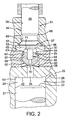
- Figure 2 shows a first embodiment of the Invention with a control valve member, which is an intermediate valve member actuated a first embodiment
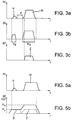
- Figure 3a to Figure 3c shows the stroke profiles of Injector valve member, control valve member and intermediate valve member of the embodiment of Figure 2
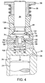
- Figure 4 a modification of the embodiment of Figure 2 with an intermediate valve member, the connecting channel through the control valve member is closable and Figures 5a to 5b the stroke profiles of the injection valve member, control valve member and intermediate valve member of the embodiment Figure 4.
- a fuel injector with which at high Injection pressures a large variation with little effort the fuel injection with respect to the injection quantity and Injection time is possible is through a so-called Common Rail System implemented.
- the invention is fundamental also with conventional fuel injection pumps usable.
- the use is particularly advantageous with a common rail injection system.
- a high-pressure fuel reservoir as a high-pressure fuel source 1 provided by a high pressure fuel delivery pump 2 from a fuel tank 4 is supplied with fuel.
- the pressure in the high-pressure fuel reservoir 1 is by a pressure sensor 6 detected and as a signal from an electrical control device 8 supplied, the pressure in a pressure control valve 5 in High-pressure fuel reservoir controls.
- the control device also controls the opening and closing of high-pressure fuel injection valves 9, which is used to inject fuel from High-pressure fuel storage are supplied.
- the fuel injection valve has 9 a valve housing 11 on its one end that is for installation in the internal combustion engine is determined, has injection openings 12, the outlet from inside the fuel injector through a Injection valve member 14 is controlled.
- This is in the executed example as an elongated valve needle trained that a conical at one end Has sealing surface 15 with an inner Valve seat cooperates on the valve housing, from which the Remove injection openings 12.
- the injection ports can also assume that there is a blind hole connects the valve seat.
- the valve needle is in one Longitudinal bore 13 at its upper, sealing surface 15 end facing away and is on the sealing surface 15th facing away from the longitudinal bore 13 end acted upon by a compression spring 18 in the closing direction.
- valve needle 14 Between the guide in the longitudinal bore 13 and the The valve seat is the valve needle 14 from an annular space 19 surrounded, which opens into a pressure chamber 16, which in turn via a pressure line 17 in constant connection with the High-pressure fuel accumulator 1 stands.
- the valve needle 14 In the area of this Pressure chamber, the valve needle 14 has a pressure shoulder 20 on, over which they oppose the pressure in the pressure chamber 16 Force of the spring 18 in the sense of lifting the sealing surface 15 is acted upon by the valve seat.
- the valve needle continues to be driven by a plunger 21 actuated, the end of the valve needle 14 facing away 22 a control chamber 24 in a tappet guide bore 23 limited.
- This is via an inlet channel 26 in which one Inlet throttle 28 is provided continuously with the pressure line 17 or the high-pressure fuel reservoir 1 connected.
- the inlet channel opens to the side and cannot be closed in the control room 24.
- Coaxial to the plunger 21 leads from the control room 24 from a connecting channel 29, which in a valve chamber 30 of a control valve 31 opens.
- Connection channel which is also a drain channel is a diameter restriction, preferably provided in the form of a discharge throttle 32.
- control valve 31 has a control valve member 34 consisting of a Valve tappet 35, which is guided in a tappet bore 36, and a valve head 37 on the valve chamber 30 projecting end of the control valve member 34.
- a spring plate 38 is provided at the Valve head opposite end of the valve lifter 35 on which there is a compression spring 39 supports, which strives to the control valve member in Bring closed position.
- the control valve member 34 is actuated by a piston 40 acted upon, which is part of a piezo actuator 41 and Exciting the piezo depending on the degree of excitement Control valve member in different open positions can bring.
- the piston can directly with the piezo be connected to the piezo actuator or by means of a hydraulic or mechanical translation of this be moved.
- valve head 37 arranged at the end of the valve tappet 35 has a conical, the entry of the connecting channel 29 valve head sealing surface 51 facing away from valve chamber 30 on, which cooperates with the valve seat 46 and so the Connection between the valve chamber 30 and the annular chamber 48 or the subsequent drain channel 49 controls.
- the Annulus 48 is in this case in contact with the valve head sealing surface 37 subsequent recess on the circumference of the Valve tappet 35 in connection with that of the valve chamber 30 laxative tappet bore 36 is formed.
- the side of the valve head facing the connecting channel 29 has a flat end face 53 which, when the valve lifter is actuated 35 in contact with an end face 54 of an intermediate valve 56 forming intermediate valve member 57 comes to rest and with a further actuation of the valve tappet 35, the intermediate valve member 57 is movable from its closed position.
- the intermediate valve member 57 has ribs 59 on its outer circumference between which flow cross sections are formed and which are guided with their end faces in a guide bore 60 become.
- the guide bore 60 tapers to the side of the Valve chamber 30 in over a sealing seat shoulder 62 to one end the valve chamber 30 coaxially to the guide bore Connection bore 63.
- the sealing seat shoulder 62 thus represents the Valve seat of the intermediate valve member.
- the part of the intermediate valve member 57 which carries the ribs 59 tapers after the ribs over a conical Sealing surface 64 to a cylindrical actuating part 65, the at a distance to the connection hole through this in the Valve chamber 30 protrudes.
- a closing spring 68 On the opposite side Intermediate valve member 57 loaded by a closing spring 68, the the intermediate valve member with its sealing surface 64 in contact brings the sealing seat shoulder 62.
- the closing spring 68 is supported thereby at the transition between the guide bore 60 and the continuing section 29 of the drain channel from the coaxial to the guide bore 60 opens into the control chamber 24.
- An axial connecting channel leads through the intermediate valve member 57 69, which is also in the closed position Intermediate valve member 57, the valve chamber 30 via the section 29 of the drain channel connects to the control room 24.
- the connecting channel can be carried out as a stepped bore from the one stepped bore part 70, the one to the control room side 24 lies and with a smaller diameter a first Connection cross section determined.
- the mode of operation of the configuration according to FIG. 2 is such that that to trigger a fuel injection with With the help of the control valve 31, the pressure in the control chamber 24 is reduced is opened by the drain channel 29, 70, 69, 30, 48, 49 becomes. Decoupled by the throttle 28 in the inflow channel 26, decreases the pressure in the control chamber 24 such that the valve member below Action of the opening forces of the pressure chamber 60 against the Force of the spring 18 opens.
- the degree of opening of the injector member 14 can by the size of the discharge of Control room or the amount of pressure medium flowing out there or fuel are affected. Guides the control valve member 34 only a partial stroke, such that the end face 53 is not in System with the intermediate valve member 57 arrives, the maximum flow through section 70 of the connecting channel 69 determined.
- the relief rate is correspondingly low thus the stroke of the injection valve member 14 only a small amount of fuel injection, for example Introduction of a pre-injection quantity promoted in the combustion chamber.
- the control valve member 34 opens completely and comes while in contact with the intermediate valve member 57, this lifts the actuating part 65 from the sealing seat shoulder 62 and provides one in addition to the first cross section second connection cross section, which is determined by section 70 is available.
- the second connection cross section can either through the passage cross-section between the sealing seat shoulder 62 and sealing surface 64 can be determined or it can Cross-section of connection through the remaining passage area be defined between the ribs 59.
- the partial relief of the control room 24 for performing the Pre-injection has the advantage that when closing the Control valve member 34, the pressure, since less lowered, can rebuild very quickly.
- FIGS. 3a to 3d show the stroke of the injection valve member 14 over time.
- the stroke of the injection valve element for the pre-injection V and the stroke of the injection valve element for carrying out the main injection quantity H can be seen there. These are interrupted by an injection break P.
- the necessary stroke of the control valve member 34 is shown with a small stroke V S and a large stroke H S.
- the stroke of the intermediate valve member Z is plotted over time with the assignment to the stroke H S of the control valve member 34 and the stroke H for the main injection of the injection valve member 14.
- FIG. 4 is a second embodiment of the invention shown as a modification to the embodiment according to FIG. 2.
- the valve head has 134 instead of the flat end face 53 now a conical, formed as a sealing surface end face 73, which with a Valve seat 74 formed end face of the intermediate valve member 157 works together.
- the valve seat 74 surrounds the at Intermediate valve member 57 of Figure 2 provided axial connection channel 69 in the area of its outlet on the actuating part 65 in the valve chamber 30.
- leaf spring 68 is now a coil spring 168 provided that the intermediate valve member 157 from the side of the Control chamber 24 loaded here and this with its sealing surface 64 holds in contact with the sealing seat shoulder 62, as long as that The intermediate valve member 57 is not lifted from the control valve member 134 becomes.
- part 70 of the connecting channel 69 again the first connection cross section between control chamber 24 and valve chamber 30, however when the control valve member 134 with its valve head 137 comes into contact with the conical valve seat 74, closed becomes. But now by lifting the intermediate valve member 157 the second connection cross-section between the ribs 59 or between the sealing seat shoulder 62 and the sealing surface 64 open.
- the second connection cross-section is like this designed that it is correspondingly larger than the first Connection cross section 70 of the part of the connection channel 69 taking into account that here the flow cross section of the second connection cross-section in place of the passage cross-section of the first connection cross-section occurs.
- This Design can be cheaper in individual cases to the exact to be able to define the second connection cross-section.
- FIG. 5a the stroke of the injection valve member 14 over time is shown analogously to FIG. 3a, likewise with the stroke V for the pre-injection and the stroke H for the main injection.
- FIG. 5b the further advantage of the embodiment according to FIG. 4 is that the control valve member does not have to be returned to its original closed position to interrupt the fuel injection between the pre-injection V and the main injection H.
- the control valve member 134 executes a stroke hv and thereby comes to bear against the conical valve seat 74 of the intermediate valve member.
- the relief of the control chamber 24 is determined by the first connection cross section of the part 70 of the connection channel 69, which leads to the pre-injection. Then, when the connecting channel 69 is closed, the pressure in the control chamber 24 can build up again and the injection valve member can close.
- the control valve member 134 is moved further up to the stroke h h and thereby opens the intermediate valve member according to the stroke curve Z. With this opening of the intermediate valve, the relief of the control chamber 24 takes place with a higher relief rate and accordingly the opening stroke of the injection valve member required for the main injection is made possible.
Landscapes
- Engineering & Computer Science (AREA)
- Chemical & Material Sciences (AREA)
- Combustion & Propulsion (AREA)
- Mechanical Engineering (AREA)
- General Engineering & Computer Science (AREA)
- Physics & Mathematics (AREA)
- Fluid Mechanics (AREA)
- Fuel-Injection Apparatus (AREA)
Applications Claiming Priority (2)
| Application Number | Priority Date | Filing Date | Title |
|---|---|---|---|
| DE19860397A DE19860397A1 (de) | 1998-12-28 | 1998-12-28 | Kraftstoffeinspritzvorrichtung für Brennkraftmaschinen |
| DE19860397 | 1998-12-28 |
Publications (3)
| Publication Number | Publication Date |
|---|---|
| EP1016783A2 true EP1016783A2 (fr) | 2000-07-05 |
| EP1016783A3 EP1016783A3 (fr) | 2002-10-23 |
| EP1016783B1 EP1016783B1 (fr) | 2004-03-17 |
Family
ID=7892896
Family Applications (1)
| Application Number | Title | Priority Date | Filing Date |
|---|---|---|---|
| EP99124452A Expired - Lifetime EP1016783B1 (fr) | 1998-12-28 | 1999-12-08 | Dispositif d'injection de carburant pour moteurs à combustion |
Country Status (4)
| Country | Link |
|---|---|
| US (1) | US6168096B1 (fr) |
| EP (1) | EP1016783B1 (fr) |
| JP (1) | JP2000192870A (fr) |
| DE (2) | DE19860397A1 (fr) |
Cited By (2)
| Publication number | Priority date | Publication date | Assignee | Title |
|---|---|---|---|---|
| WO2003004856A1 (fr) * | 2001-06-29 | 2003-01-16 | Robert Bosch Gmbh | Injecteur de carburant avec mise en forme de la courbe d'injection au moyen d'elements d'etranglement commandes |
| EP1795738A1 (fr) * | 2005-12-12 | 2007-06-13 | C.R.F. Societa Consortile per Azioni | Système d'injection de carburant pour un moteur à combustion interne et méthode correspondante pour commander l'injection de carburant |
Families Citing this family (14)
| Publication number | Priority date | Publication date | Assignee | Title |
|---|---|---|---|---|
| DE19951964A1 (de) * | 1999-10-28 | 2001-05-03 | Bosch Gmbh Robert | Kraftstoffeinspritzventil für Brennkraftmaschinen |
| US6439201B1 (en) * | 2000-12-20 | 2002-08-27 | Caterpillar Inc. | Fuel injector having dual flow rate capabilities and engine using same |
| FR2819021B1 (fr) * | 2000-12-28 | 2005-03-04 | Denso Corp | Soupape de commande hydraulique et injecteur de carburant utilisant une telle soupape |
| DE10122246A1 (de) * | 2001-05-08 | 2002-11-21 | Bosch Gmbh Robert | Injektor zum Einspritzen von Kraftstoff mit in Reihe geschalteten Steuerventilgliedern |
| ITTO20010970A1 (it) * | 2001-10-12 | 2003-04-12 | Fiat Ricerche | Inettore di combustibile per un motore a combustione interna. |
| GB0215490D0 (en) * | 2002-07-04 | 2002-08-14 | Delphi Tech Inc | Control valve arrangement |
| US20070235554A1 (en) * | 2006-03-29 | 2007-10-11 | Williams Arthur R | Dual stroke injector using SMA |
| JP5262933B2 (ja) | 2009-04-03 | 2013-08-14 | 株式会社デンソー | 燃料噴射装置 |
| JP5565291B2 (ja) * | 2010-12-08 | 2014-08-06 | 株式会社デンソー | 燃料噴射装置 |
| HUE027510T2 (en) * | 2012-04-05 | 2016-10-28 | Delphi Int Operations Luxembourg Sarl | valve Layout |
| EP2975257B1 (fr) * | 2014-07-18 | 2018-01-10 | Continental Automotive GmbH | Unité de commande pour commander une tige de soupape d'un injecteur de carburant et injecteur de carburant |
| DE102016216885A1 (de) | 2016-09-06 | 2018-03-08 | Continental Automotive Gmbh | Fluidinjektor für ein Kraftfahrzeug |
| JP6919344B2 (ja) * | 2017-06-06 | 2021-08-18 | 株式会社Soken | 燃料噴射装置 |
| GB2567171A (en) * | 2017-10-04 | 2019-04-10 | Delphi Tech Ip Ltd | Fuel injector |
Family Cites Families (13)
| Publication number | Priority date | Publication date | Assignee | Title |
|---|---|---|---|---|
| US4603671A (en) * | 1983-08-17 | 1986-08-05 | Nippon Soken, Inc. | Fuel injector for an internal combustion engine |
| IT212431Z2 (it) * | 1987-08-25 | 1989-07-04 | Weber Srl | Le a comando elettromagnetico per valvola di iniezione del combustibi motori a ciclo diesel |
| JP3144136B2 (ja) * | 1993-03-31 | 2001-03-12 | 株式会社デンソー | 三方電磁弁 |
| IT232490Y1 (it) * | 1994-07-01 | 2000-01-10 | Elasis Sistema Ricerca Fiat | Dispositivo di registrazione della corsa dell'otturatore per un iniettore di combustibile |
| DE19616812B4 (de) * | 1995-04-27 | 2004-09-30 | Nippon Soken, Inc., Nishio | Kraftstoffeinspritzvorrichtung |
| JP3584554B2 (ja) * | 1995-07-26 | 2004-11-04 | 株式会社デンソー | 蓄圧式燃料噴射装置 |
| JP3446432B2 (ja) * | 1995-12-05 | 2003-09-16 | 株式会社デンソー | 燃料噴射装置 |
| DE19647304C1 (de) * | 1996-11-15 | 1998-01-22 | Daimler Benz Ag | Kraftstoffeinspritzanlage für eine Brennkraftmaschine |
| US5860597A (en) * | 1997-03-24 | 1999-01-19 | Cummins Engine Company, Inc. | Injection rate shaping nozzle assembly for a fuel injector |
| DE19748999C2 (de) * | 1997-11-06 | 2002-11-07 | Daimler Chrysler Ag | Magnetventilgesteuerter Injektor für ein Speichersystem einer mehrzylindrigen Brennkraftmaschine |
| DE19816316A1 (de) * | 1998-04-11 | 1999-10-14 | Bosch Gmbh Robert | Kraftstoffeinspritzvorrichtung für Brennkraftmaschinen |
| US6092737A (en) * | 1999-02-02 | 2000-07-25 | General Motors Corporation | Direct acting fuel injector |
| DE19940290A1 (de) * | 1999-08-25 | 2001-03-01 | Bosch Gmbh Robert | Steuerventil für ein Kraftstoffeinspritzventil |
-
1998
- 1998-12-28 DE DE19860397A patent/DE19860397A1/de not_active Withdrawn
-
1999
- 1999-12-08 DE DE59908876T patent/DE59908876D1/de not_active Expired - Fee Related
- 1999-12-08 EP EP99124452A patent/EP1016783B1/fr not_active Expired - Lifetime
- 1999-12-17 US US09/465,844 patent/US6168096B1/en not_active Expired - Fee Related
- 1999-12-24 JP JP11367590A patent/JP2000192870A/ja active Pending
Cited By (3)
| Publication number | Priority date | Publication date | Assignee | Title |
|---|---|---|---|---|
| WO2003004856A1 (fr) * | 2001-06-29 | 2003-01-16 | Robert Bosch Gmbh | Injecteur de carburant avec mise en forme de la courbe d'injection au moyen d'elements d'etranglement commandes |
| EP1795738A1 (fr) * | 2005-12-12 | 2007-06-13 | C.R.F. Societa Consortile per Azioni | Système d'injection de carburant pour un moteur à combustion interne et méthode correspondante pour commander l'injection de carburant |
| US7240859B2 (en) | 2005-12-12 | 2007-07-10 | Crf Societa Consortile Per Azioni | Fuel-injection system for an internal-combustion engine and corresponding method for controlling fuel injection |
Also Published As
| Publication number | Publication date |
|---|---|
| DE59908876D1 (de) | 2004-04-22 |
| EP1016783B1 (fr) | 2004-03-17 |
| JP2000192870A (ja) | 2000-07-11 |
| EP1016783A3 (fr) | 2002-10-23 |
| US6168096B1 (en) | 2001-01-02 |
| DE19860397A1 (de) | 2000-06-29 |
Similar Documents
| Publication | Publication Date | Title |
|---|---|---|
| EP0949415B1 (fr) | Dispositif d'injection de combustible pour moteurs à combustion interne | |
| EP0925440B1 (fr) | Injecteur de carburant | |
| EP0960274B1 (fr) | Dispositif d'injection de carburant pour moteurs a combustion interne | |
| EP1016783B1 (fr) | Dispositif d'injection de carburant pour moteurs à combustion | |
| EP1332282B1 (fr) | Electrovanne pour piloter une soupape d'injection de moteur a combustion interne | |
| WO1997048900A1 (fr) | Dispositif d'injection de carburant pour moteurs a combustion interne | |
| WO2003071122A1 (fr) | Soupape d'injection de carburant pour moteurs a combustion interne | |
| WO2001029395A2 (fr) | Dispositif de commande hydraulique, en particulier pour un injecteur | |
| EP2735725A1 (fr) | Soupape d'injection de carburant pour moteurs à combustion interne | |
| DE19844891A1 (de) | Kraftstoffeinspritzventil für Brennkraftmaschinen | |
| DE10222411B4 (de) | Brennstoffeinspritzventil mit variablem Hub | |
| DE10205185A1 (de) | Kraftstoffeinspritzeinrichtung für eine Brennkraftmaschine | |
| EP1651858B1 (fr) | Dispositif d'injection de carburant pour moteur a combustion interne | |
| DE102009026564A1 (de) | Kraftstoff-Injektor mit druckausgeglichenem Steuerventil | |
| DE102005026967B4 (de) | Ventil, insbesondere Servoventil | |
| DE10050599B4 (de) | Einspritzventil mit einem Pumpkolben | |
| DE10132248A1 (de) | Kraftstoffinjektor mit 2-Wege-Ventilsteuerung | |
| EP1384000A1 (fr) | Dispositif d'injection de carburant pour moteur a combustion | |
| EP0752060B1 (fr) | Soupape d'injection | |
| DE10160258A1 (de) | Kraftstoffeinspritzeinrichtung für eine Brennkraftmaschine | |
| WO2010000528A1 (fr) | Vanne magnétique pour un injecteur de carburant et injecteur de carburant | |
| DE102004042189B4 (de) | Ventil | |
| EP1176306A2 (fr) | Système d'injection de combustible pour moteurs à combustion interne | |
| WO2008086941A1 (fr) | Injecteur de carburant à coupleur | |
| WO2001014721A1 (fr) | Dispositif d'injection de carburant pour moteurs a combustion interne |
Legal Events
| Date | Code | Title | Description |
|---|---|---|---|
| PUAI | Public reference made under article 153(3) epc to a published international application that has entered the european phase |
Free format text: ORIGINAL CODE: 0009012 |
|
| AK | Designated contracting states |
Kind code of ref document: A2 Designated state(s): AT BE CH CY DE DK ES FI FR GB GR IE IT LI LU MC NL PT SE |
|
| AX | Request for extension of the european patent |
Free format text: AL;LT;LV;MK;RO;SI |
|
| PUAL | Search report despatched |
Free format text: ORIGINAL CODE: 0009013 |
|
| AK | Designated contracting states |
Kind code of ref document: A3 Designated state(s): AT BE CH CY DE DK ES FI FR GB GR IE IT LI LU MC NL PT SE |
|
| AX | Request for extension of the european patent |
Free format text: AL;LT;LV;MK;RO;SI |
|
| RIC1 | Information provided on ipc code assigned before grant |
Free format text: 7F 02M 47/02 A, 7F 02M 59/46 B, 7F 02M 45/08 B |
|
| GRAH | Despatch of communication of intention to grant a patent |
Free format text: ORIGINAL CODE: EPIDOS IGRA |
|
| 17P | Request for examination filed |
Effective date: 20030423 |
|
| AKX | Designation fees paid |
Designated state(s): DE FR GB |
|
| GRAS | Grant fee paid |
Free format text: ORIGINAL CODE: EPIDOSNIGR3 |
|
| GRAA | (expected) grant |
Free format text: ORIGINAL CODE: 0009210 |
|
| AK | Designated contracting states |
Kind code of ref document: B1 Designated state(s): DE FR GB |
|
| PG25 | Lapsed in a contracting state [announced via postgrant information from national office to epo] |
Ref country code: GB Free format text: LAPSE BECAUSE OF FAILURE TO SUBMIT A TRANSLATION OF THE DESCRIPTION OR TO PAY THE FEE WITHIN THE PRESCRIBED TIME-LIMIT Effective date: 20040317 Ref country code: FR Free format text: LAPSE BECAUSE OF FAILURE TO SUBMIT A TRANSLATION OF THE DESCRIPTION OR TO PAY THE FEE WITHIN THE PRESCRIBED TIME-LIMIT Effective date: 20040317 |
|
| REG | Reference to a national code |
Ref country code: GB Ref legal event code: FG4D Free format text: NOT ENGLISH |
|
| REG | Reference to a national code |
Ref country code: IE Ref legal event code: FG4D Free format text: GERMAN |
|
| REF | Corresponds to: |
Ref document number: 59908876 Country of ref document: DE Date of ref document: 20040422 Kind code of ref document: P |
|
| GBV | Gb: ep patent (uk) treated as always having been void in accordance with gb section 77(7)/1977 [no translation filed] |
Effective date: 20040317 |
|
| REG | Reference to a national code |
Ref country code: IE Ref legal event code: FD4D |
|
| PLBE | No opposition filed within time limit |
Free format text: ORIGINAL CODE: 0009261 |
|
| STAA | Information on the status of an ep patent application or granted ep patent |
Free format text: STATUS: NO OPPOSITION FILED WITHIN TIME LIMIT |
|
| EN | Fr: translation not filed | ||
| 26N | No opposition filed |
Effective date: 20041220 |
|
| PG25 | Lapsed in a contracting state [announced via postgrant information from national office to epo] |
Ref country code: DE Free format text: LAPSE BECAUSE OF NON-PAYMENT OF DUE FEES Effective date: 20050701 |