EP1016815A2 - Ensemble de suspension pour aimant supraconducteur - Google Patents
Ensemble de suspension pour aimant supraconducteur Download PDFInfo
- Publication number
- EP1016815A2 EP1016815A2 EP99310349A EP99310349A EP1016815A2 EP 1016815 A2 EP1016815 A2 EP 1016815A2 EP 99310349 A EP99310349 A EP 99310349A EP 99310349 A EP99310349 A EP 99310349A EP 1016815 A2 EP1016815 A2 EP 1016815A2
- Authority
- EP
- European Patent Office
- Prior art keywords
- suspension system
- superconducting magnet
- radiation shield
- thermal
- pressure vessel
- Prior art date
- Legal status (The legal status is an assumption and is not a legal conclusion. Google has not performed a legal analysis and makes no representation as to the accuracy of the status listed.)
- Granted
Links
- 239000000725 suspension Substances 0.000 title claims abstract description 33
- 230000005855 radiation Effects 0.000 claims abstract description 22
- 229920000049 Carbon (fiber) Polymers 0.000 claims abstract description 7
- 239000004917 carbon fiber Substances 0.000 claims abstract description 7
- 239000002131 composite material Substances 0.000 claims abstract description 7
- VNWKTOKETHGBQD-UHFFFAOYSA-N methane Chemical compound C VNWKTOKETHGBQD-UHFFFAOYSA-N 0.000 claims abstract description 7
- 239000001307 helium Substances 0.000 claims description 12
- 229910052734 helium Inorganic materials 0.000 claims description 12
- SWQJXJOGLNCZEY-UHFFFAOYSA-N helium atom Chemical compound [He] SWQJXJOGLNCZEY-UHFFFAOYSA-N 0.000 claims description 12
- 238000002595 magnetic resonance imaging Methods 0.000 claims description 10
- XAGFODPZIPBFFR-UHFFFAOYSA-N aluminium Chemical compound [Al] XAGFODPZIPBFFR-UHFFFAOYSA-N 0.000 claims description 8
- 229910052782 aluminium Inorganic materials 0.000 claims description 8
- 230000000712 assembly Effects 0.000 claims description 7
- 238000000429 assembly Methods 0.000 claims description 7
- 238000001816 cooling Methods 0.000 claims description 7
- 229910001220 stainless steel Inorganic materials 0.000 claims description 5
- 239000010935 stainless steel Substances 0.000 claims description 5
- 230000008646 thermal stress Effects 0.000 claims description 3
- 239000007789 gas Substances 0.000 claims description 2
- 238000003466 welding Methods 0.000 claims 2
- 239000004918 carbon fiber reinforced polymer Substances 0.000 description 13
- 230000002787 reinforcement Effects 0.000 description 6
- 239000007788 liquid Substances 0.000 description 5
- 239000000463 material Substances 0.000 description 4
- 230000008602 contraction Effects 0.000 description 3
- 238000009835 boiling Methods 0.000 description 2
- 238000003384 imaging method Methods 0.000 description 2
- 238000009413 insulation Methods 0.000 description 2
- 238000002955 isolation Methods 0.000 description 2
- 206010009244 Claustrophobia Diseases 0.000 description 1
- IZDLMEDQWQMDOK-UHFFFAOYSA-N aluminum helium Chemical compound [He].[Al] IZDLMEDQWQMDOK-UHFFFAOYSA-N 0.000 description 1
- 238000010276 construction Methods 0.000 description 1
- 230000000694 effects Effects 0.000 description 1
- 230000000977 initiatory effect Effects 0.000 description 1
- 238000009434 installation Methods 0.000 description 1
- 238000003754 machining Methods 0.000 description 1
- 238000000034 method Methods 0.000 description 1
- 238000012986 modification Methods 0.000 description 1
- 230000004048 modification Effects 0.000 description 1
- 230000002085 persistent effect Effects 0.000 description 1
- 208000019899 phobic disease Diseases 0.000 description 1
- 238000012827 research and development Methods 0.000 description 1
- 125000006850 spacer group Chemical group 0.000 description 1
Images


Classifications
-
- H—ELECTRICITY
- H01—ELECTRIC ELEMENTS
- H01F—MAGNETS; INDUCTANCES; TRANSFORMERS; SELECTION OF MATERIALS FOR THEIR MAGNETIC PROPERTIES
- H01F6/00—Superconducting magnets; Superconducting coils
-
- G—PHYSICS
- G01—MEASURING; TESTING
- G01R—MEASURING ELECTRIC VARIABLES; MEASURING MAGNETIC VARIABLES
- G01R33/00—Arrangements or instruments for measuring magnetic variables
- G01R33/20—Arrangements or instruments for measuring magnetic variables involving magnetic resonance
- G01R33/28—Details of apparatus provided for in groups G01R33/44 - G01R33/64
- G01R33/38—Systems for generation, homogenisation or stabilisation of the main or gradient magnetic field
- G01R33/381—Systems for generation, homogenisation or stabilisation of the main or gradient magnetic field using electromagnets
- G01R33/3815—Systems for generation, homogenisation or stabilisation of the main or gradient magnetic field using electromagnets with superconducting coils, e.g. power supply therefor
-
- Y—GENERAL TAGGING OF NEW TECHNOLOGICAL DEVELOPMENTS; GENERAL TAGGING OF CROSS-SECTIONAL TECHNOLOGIES SPANNING OVER SEVERAL SECTIONS OF THE IPC; TECHNICAL SUBJECTS COVERED BY FORMER USPC CROSS-REFERENCE ART COLLECTIONS [XRACs] AND DIGESTS
- Y10—TECHNICAL SUBJECTS COVERED BY FORMER USPC
- Y10S—TECHNICAL SUBJECTS COVERED BY FORMER USPC CROSS-REFERENCE ART COLLECTIONS [XRACs] AND DIGESTS
- Y10S220/00—Receptacles
- Y10S220/901—Liquified gas content, cryogenic
-
- Y—GENERAL TAGGING OF NEW TECHNOLOGICAL DEVELOPMENTS; GENERAL TAGGING OF CROSS-SECTIONAL TECHNOLOGIES SPANNING OVER SEVERAL SECTIONS OF THE IPC; TECHNICAL SUBJECTS COVERED BY FORMER USPC CROSS-REFERENCE ART COLLECTIONS [XRACs] AND DIGESTS
- Y10—TECHNICAL SUBJECTS COVERED BY FORMER USPC
- Y10S—TECHNICAL SUBJECTS COVERED BY FORMER USPC CROSS-REFERENCE ART COLLECTIONS [XRACs] AND DIGESTS
- Y10S505/00—Superconductor technology: apparatus, material, process
- Y10S505/825—Apparatus per se, device per se, or process of making or operating same
- Y10S505/888—Refrigeration
Definitions
- This invention relates to a suspension system for a superconducting magnet assembly for a magnetic resonance imager (hereinafter called "MRI") and in particular to the suspension for an open architecture magnet assembly.
- MRI magnetic resonance imager
- a superconducting magnet can be made superconducting by placing it in an extremely cold environment, such as by enclosing it in a cryostat or pressure vessel containing liquid helium or other cryogen cryocoolant means.
- the extreme cold ensures that the magnet coils are superconducting, such that the coils can be operated in the persistent mode, that is when a power source is initially connected to the coil for a relatively short period of time to introduce a current flow through the coils and a superconducting switch is then closed, the current will continue to flow, thereby maintaining the coil current and a magnetic field.
- Superconducting magnets find wide application in the field of MRI.
- Another problem encountered by most MRI equipments is that they utilize solenoidal magnets enclosed in cylindrical structures with a central bore opening for patient access.
- the patient is practically enclosed in the warm bore, which can induce claustrophobia in some patients.
- the desirability of an open architecture structure in which the patient is not essentially totally enclosed has long been recognized.
- an open architecture structure poses a number of technical problems and challenges.
- One problem is to provide a suitable support structure which occupies much less space than conventional support structures, and yet which nevertheless can support the magnet assembly under the considerable electromagnetic forces and thermal forces encountered during operation.
- the suspension system of an MRI magnet has to support the magnet mass, while providing adequate stiffness with minimal conduction heat leak.
- an open architecture MRI suspension must support a large electro-magnetic (EM) net force in each half of the magnet in the axial direction as well as a possible transverse EM force due to misalignment.
- EM electro-magnetic
- the stiffness requirement in all directions is also more demanding in such an assembly in order to provide field stability under vibration.
- all of the structural requirements should be met without significant increase of conduction heat leak through the suspension system.
- a superconducting magnet suitable for magnetic resonance imaging and including a cryogen pressure vessel concentric within a vacuum vessel and a thermal radiation shield interposed between the vessels and extending along the axis thereof, a suspension system to position and maintain the spaced relationship between the cryogen pressure vessel, the thermal radiation shield and the vacuum vessel comprising: a first support assembly extending between said cryogen pressure vessel and said radiation shield; and a second support assembly extending between said radiation shield and said vacuum vessel;
- FIG. 1 is a simplified side view, partially cut away of an open architecture superconducting magnet assembly incorporating the invention.
- FIG. 2 is an enlarged simplified perspective view of the unitary support structure of FIG. 1 which is not to scale in order to better illustrate the invention.
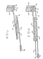
- FIG. 3 is a cross section including details of the support structure of FICs. 1 and 2.
- FIG. 4 is a cross section of a modified version of FIG. 3.
- open architecture superconducting magnet assembly 10 includes a pair of separated solenoidal or cylindrical shaped vacuum vessels or housings 12 or 14 of superconducting magnets 6 and 8 separated by a support structure 16.
- the overall structure formed by vacuum vessels 12 and 14 and spacer posts 16 provides substantial openings or open space between the vacuum vessels which avoids a closure of the patient positioned in the open space or imaging region 11 around axis 32 of superconducting magnets 6 and 8.
- a plurality of main magnet coil shown generally as 24 within cryogen pressure vessel 22 provides a strong magnetic field in imaging region 11 upon cooling of magnet assembly 10 to superconducting temperatures (by conventional helium cooling means - not shown) and the initiation of superconducting magnet current flow.
- Recondenser 15 recondenses helium gas resulting from the boiling of helium in cooling superconducting magnets 6 and 8 to superconducting temperatures.
- the recondensed liquid helium flows back as indicated by arrow 17 to the superconducting magnets in a manner well known in the art.
- CFRP carbon fiber reinforced composite
- conical shaped CW support assembly 40 includes 3 sections.
- a first generally frustro-conical or conical section 42 extends between cryogen pressure vessel 22 and thermal radiation shield 30, a second overlapping generally frustro-conical or conical section 44 connects thermal shield 30 and vacuum vessel 12, and a third or reentry section 46 connecting between conical sections 42 and 44.
- Reentry section 46 is substantially cylindrical and concentric about axis 11.
- CFRP support assembly 40 sections 42, 44 and 46 are wound and assembled together to form a unitary assembly or member as best illustrated in FIG. 2.
- the intermediate cylindrical reentrant cylinder 46 lengthens the thermal path of support assembly 40 and uses the same CFRP material to match the thermal shrinkage of the suspension cones 42 and 44.
- CFRP support assembly 40 as a result not only provides great strength in both the axial and radial directions, it also provides a lengthened generally Z-shaped thermal path which avoids unacceptable thermal conductivity which might otherwise occur because of the relatively short distance between cryogen pressure vessel 22 and vacuum vessel 12 within the confines of the open architecture superconducting magnets 6 and 8.
- conical members 42 and 44 and axial reentry cylinder 46 are wound from MP and joined together as shown.
- the attachment of frustro-conical section or member 42 to cryogen pressure vessel 22 includes CFRP reinforcement member 50 and pretension CFRP member 52 which includes screw mechanism 54 to provide the proper pretension to match the cryogen pressure vessel 22 cool-down shrinkage in order to reduce the thermal stress in CFRP support assembly 40.
- Aluminum cryogen pressure vessel 22 exhibits a much greater cool-down shrinkage during cooling from room temperature to cryogenic temperature than does the CFRP material forming support assembly 40. In order to provide the proper mechanical interface at both room and cryogenic temperatures, and to minimize the impact of thermal shrinkage differences, an expanding interface is provided.
- CFRP reinforcement member 50 is made smaller than the cryogen pressure vessel interface 22 at room temperature resulting in a radial gap between reinforcement member 50 and pressure vessel 22.
- the diameter of reinforcement member 50 is smaller than cryogen pressure vessel 22 interface at room temperature but larger when they differentially shrink at superconducting temperatures such as 4.2 K.
- Screw mechanism 54 is used to close the gap during assembly by expanding - the diameter of the reinforcement member.
- Stainless steel ring 60 is overlapped by stainless steel segment 61 to capture a step on CFRP member 44. This joint provides a weld surface 60 for the attachment of support assembly 40 to vacuum vessel 12.
- FIG. 4 shows a slight modification of CFRP support assembly 40.
- support assembly 41 includes the addition of segmented thin aluminum sheet 58 such as AL 1100 bonded to axial cylinder 46 to provide a mechanical and thermal joint between the suspension system support assembly 40 and thermal radiation shield 30 and to enhance the heat shielding or heat interception effect.
Landscapes
- Physics & Mathematics (AREA)
- Engineering & Computer Science (AREA)
- Power Engineering (AREA)
- Electromagnetism (AREA)
- Condensed Matter Physics & Semiconductors (AREA)
- General Physics & Mathematics (AREA)
- Containers, Films, And Cooling For Superconductive Devices (AREA)
- Magnetic Resonance Imaging Apparatus (AREA)
Applications Claiming Priority (2)
| Application Number | Priority Date | Filing Date | Title |
|---|---|---|---|
| US223514 | 1981-01-08 | ||
| US09/223,514 US6011454A (en) | 1998-12-30 | 1998-12-30 | Superconducting magnet suspension assembly |
Publications (3)
| Publication Number | Publication Date |
|---|---|
| EP1016815A2 true EP1016815A2 (fr) | 2000-07-05 |
| EP1016815A3 EP1016815A3 (fr) | 2002-10-30 |
| EP1016815B1 EP1016815B1 (fr) | 2006-03-22 |
Family
ID=22836838
Family Applications (1)
| Application Number | Title | Priority Date | Filing Date |
|---|---|---|---|
| EP99310349A Expired - Lifetime EP1016815B1 (fr) | 1998-12-30 | 1999-12-21 | Ensemble de suspension pour aimant supraconducteur |
Country Status (4)
| Country | Link |
|---|---|
| US (1) | US6011454A (fr) |
| EP (1) | EP1016815B1 (fr) |
| JP (1) | JP4587136B2 (fr) |
| DE (1) | DE69930487T2 (fr) |
Cited By (1)
| Publication number | Priority date | Publication date | Assignee | Title |
|---|---|---|---|---|
| CN107946016A (zh) * | 2017-10-31 | 2018-04-20 | 上海联影医疗科技有限公司 | 绕线筒、超导磁体系统及磁共振系统 |
Families Citing this family (23)
| Publication number | Priority date | Publication date | Assignee | Title |
|---|---|---|---|---|
| US6172588B1 (en) * | 1999-04-23 | 2001-01-09 | General Electric Company | Apparatus and method for a superconductive magnet with pole piece |
| US6147579A (en) * | 1999-11-17 | 2000-11-14 | General Electric Company | Superconducting magnet non-uniform thermal insulation blankets |
| US6570476B1 (en) * | 2002-07-17 | 2003-05-27 | General Electric Company | Thermal shield suspension for superconductive magnets |
| US7242191B2 (en) * | 2002-11-25 | 2007-07-10 | General Electric Company | Cold mass support structure and helium vessel of actively shielded high field open MRI magnets |
| JP3624254B1 (ja) * | 2003-09-30 | 2005-03-02 | 株式会社日立製作所 | 超伝導磁石装置 |
| JP4705528B2 (ja) * | 2006-01-05 | 2011-06-22 | 株式会社日立製作所 | 超伝導磁石装置および磁気共鳴イメージング装置 |
| JP2007220907A (ja) * | 2006-02-16 | 2007-08-30 | Japan Superconductor Technology Inc | 超電導磁石装置及びその運転方法 |
| US7595715B2 (en) * | 2007-09-27 | 2009-09-29 | Lear Corporation | High power case fuse |
| US7646272B1 (en) | 2007-10-12 | 2010-01-12 | The United States Of America As Represented By The United States Department Of Energy | Freely oriented portable superconducting magnet |
| CN101884533B (zh) * | 2009-05-15 | 2012-01-25 | 美时医疗技术(上海)有限公司 | 用于乳腺诊断的超导磁共振成像仪、其构造方法及用途 |
| US8628115B2 (en) * | 2010-10-05 | 2014-01-14 | GM Global Technology Operations LLC | Impact elements for a mounting system for a pressure vessel |
| US20120309630A1 (en) * | 2011-05-31 | 2012-12-06 | General Electric Company | Penetration tube assemblies for reducing cryostat heat load |
| DE102014203351B4 (de) * | 2014-02-25 | 2017-10-19 | Fraunhofer-Gesellschaft zur Förderung der angewandten Forschung e.V. | Auflager zur Lagerung und zur thermischen Isolation von Fluidtanks |
| DE102014226550A1 (de) * | 2014-12-19 | 2016-06-23 | Bayerische Motoren Werke Aktiengesellschaft | Aufhängung zur Anbringung eines Innenbehälters an einem Außenbehälter, kryogener Druckbehälter sowie Verfahren zur Herstellung einer Aufhängung |
| DE102014226557A1 (de) * | 2014-12-19 | 2016-06-23 | Bayerische Motoren Werke Aktiengesellschaft | Aufhängung zur Anbringung eines Innenbehälters an einem Außenbehälter eines kryogenen Druckbehälters sowie kryogener Druckbehälter |
| CN105139993B (zh) * | 2015-09-23 | 2017-08-04 | 奥泰医疗系统有限责任公司 | 一种超导磁体的悬吊装置 |
| US11249156B2 (en) | 2016-04-25 | 2022-02-15 | Koninklijke Philips N.V. | Magnetic resonance radiation shield and shielded main magnet |
| WO2018143425A1 (fr) * | 2017-02-03 | 2018-08-09 | イーグル工業株式会社 | Structure d'isolation thermique et système de distribution de liquide |
| DE102017210722B4 (de) * | 2017-06-26 | 2020-05-14 | Bayerische Motoren Werke Aktiengesellschaft | Kraftfahrzeug und Druckbehälter mit divergierendem Verbindungsrohr |
| DE102018000154B4 (de) * | 2018-01-11 | 2022-10-27 | Audi Ag | Anordnung zum Anbinden eines Druckspeichers |
| DE102018212758A1 (de) * | 2018-07-31 | 2020-02-06 | Bruker Switzerland Ag | Kryostatanordnung mit supraleitendem Magnetspulensystem mit thermischer Verankerung der Befestigungsstruktur |
| GB2579074B (en) * | 2018-11-19 | 2021-02-17 | Siemens Healthcare Ltd | A self-supporting flexible thermal radiation shield |
| CN109681771B (zh) * | 2019-01-18 | 2023-10-03 | 青岛凯迪力学应用研究所有限公司 | 内胆悬浮式低温液体存储及运输容器 |
Family Cites Families (13)
| Publication number | Priority date | Publication date | Assignee | Title |
|---|---|---|---|---|
| US3037657A (en) * | 1958-03-03 | 1962-06-05 | Robert S Hampton | Conical support for jacketed vessel |
| US3781733A (en) * | 1972-12-21 | 1973-12-25 | Atomic Energy Commission | Low heat conductant temperature stabilized structural support |
| FR2410211A1 (fr) * | 1977-11-25 | 1979-06-22 | Anvar | Cryostat a cryogene liquide muni d'un dispositif monobloc de suspension ultra-rigide compatible avec l'ancrage thermique des ecrans de radiation |
| US4496073A (en) * | 1983-02-24 | 1985-01-29 | The Johns Hopkins University | Cryogenic tank support system |
| EP0375656B1 (fr) * | 1985-01-17 | 1993-11-24 | Mitsubishi Denki Kabushiki Kaisha | Réservoir cryogénique destiné à un dispositif supraconducteur |
| US4622824A (en) * | 1985-09-03 | 1986-11-18 | Ga Technologies Inc. | Cryostat suspension system |
| DE4010032C2 (de) * | 1990-03-29 | 1994-03-03 | Bruker Analytische Messtechnik | Magnetsystem |
| JP3147450B2 (ja) * | 1991-12-26 | 2001-03-19 | 株式会社日立製作所 | 超電導磁石並びに磁気浮上輸送体 |
| US5539367A (en) * | 1994-05-02 | 1996-07-23 | General Electric Company | Superconducting gradient shields in magnetic resonance imaging magnets |
| GB2299673A (en) * | 1995-04-07 | 1996-10-09 | Oxford Magnet Tech | MRI magnet with flared opening |
| US5586437A (en) * | 1995-09-06 | 1996-12-24 | Intermagnetics General Corporation | MRI cryostat cooled by open and closed cycle refrigeration systems |
| US5568104A (en) * | 1995-10-23 | 1996-10-22 | General Electric Company | Open MRI superconductive magnet with cryogenic-fluid cooling |
| US5701744A (en) * | 1996-10-31 | 1997-12-30 | General Electric Company | Magnetic resonance imager with helium recondensing |
-
1998
- 1998-12-30 US US09/223,514 patent/US6011454A/en not_active Expired - Lifetime
-
1999
- 1999-12-21 EP EP99310349A patent/EP1016815B1/fr not_active Expired - Lifetime
- 1999-12-21 DE DE69930487T patent/DE69930487T2/de not_active Expired - Lifetime
- 1999-12-27 JP JP36887699A patent/JP4587136B2/ja not_active Expired - Fee Related
Cited By (2)
| Publication number | Priority date | Publication date | Assignee | Title |
|---|---|---|---|---|
| CN107946016A (zh) * | 2017-10-31 | 2018-04-20 | 上海联影医疗科技有限公司 | 绕线筒、超导磁体系统及磁共振系统 |
| CN107946016B (zh) * | 2017-10-31 | 2020-08-18 | 上海联影医疗科技有限公司 | 绕线筒、超导磁体系统及磁共振系统 |
Also Published As
| Publication number | Publication date |
|---|---|
| JP2000357822A (ja) | 2000-12-26 |
| EP1016815A3 (fr) | 2002-10-30 |
| DE69930487T2 (de) | 2007-01-11 |
| US6011454A (en) | 2000-01-04 |
| JP4587136B2 (ja) | 2010-11-24 |
| EP1016815B1 (fr) | 2006-03-22 |
| DE69930487D1 (de) | 2006-05-11 |
Similar Documents
| Publication | Publication Date | Title |
|---|---|---|
| EP1016815B1 (fr) | Ensemble de suspension pour aimant supraconducteur | |
| US5291169A (en) | Open architecture magnetic resonance imaging superconducting magnet assembly | |
| JP3706658B2 (ja) | オーバショルダ形の磁気共鳴イメージング磁石 | |
| US8228147B2 (en) | Supported superconducting magnet | |
| JP4079504B2 (ja) | 磁気共鳴イメージング・マグネット | |
| US5278502A (en) | Refrigerated superconducting MR magnet with integrated cryogenic gradient coils | |
| EP2864802B1 (fr) | Procédé et appareil de réduction des vibrations de bobines de gradient dans des systèmes d'irm | |
| US5446433A (en) | Superconducting magnet having a shock-resistant support structure | |
| JPH11283824A (ja) | 遮蔽付き開放型超伝導磁石 | |
| US5237300A (en) | Support structure for actively shielded superconducting magnets | |
| JPS6196299A (ja) | 低温槽貫入管用の支持体 | |
| GB2484079A (en) | Cylindrical stiffener for cryoshield | |
| US5179338A (en) | Refrigerated superconducting MR magnet with integrated gradient coils | |
| US9859045B2 (en) | Superconducting magnet | |
| EP0135185B1 (fr) | Cryostat pour aimant par RMN | |
| CN108692187B (zh) | 低温恒温器布置系统 | |
| JP2018534759A (ja) | Hts磁石のための支持構造体 | |
| US5696476A (en) | Open architecture magnetic resonance imaging superconducting magnet assembly | |
| JPH0317385B2 (fr) | ||
| EP1102078B1 (fr) | Architecture ouverte d'aimant supraconducteur comportant un réservoir d'hélium | |
| JPH0559567B2 (fr) | ||
| US5225782A (en) | Eddy current free MRI magnet with integrated gradient coils | |
| US6323749B1 (en) | MRI with superconducting coil | |
| US6147579A (en) | Superconducting magnet non-uniform thermal insulation blankets | |
| JP7404517B2 (ja) | コイル支持体 |
Legal Events
| Date | Code | Title | Description |
|---|---|---|---|
| PUAI | Public reference made under article 153(3) epc to a published international application that has entered the european phase |
Free format text: ORIGINAL CODE: 0009012 |
|
| AK | Designated contracting states |
Kind code of ref document: A2 Designated state(s): AT BE CH CY DE DK ES FI FR GB GR IE IT LI LU MC NL PT SE |
|
| AX | Request for extension of the european patent |
Free format text: AL;LT;LV;MK;RO;SI |
|
| PUAL | Search report despatched |
Free format text: ORIGINAL CODE: 0009013 |
|
| RIC1 | Information provided on ipc code assigned before grant |
Free format text: 7F 17C 13/00 A, 7F 17C 3/08 B, 7H 01F 6/06 B, 7F 17C 13/08 B, 7G 01R 33/3815 B, 7H 01L 39/04 B |
|
| AK | Designated contracting states |
Kind code of ref document: A3 Designated state(s): AT BE CH CY DE DK ES FI FR GB GR IE IT LI LU MC NL PT SE |
|
| AX | Request for extension of the european patent |
Free format text: AL;LT;LV;MK;RO;SI |
|
| 17P | Request for examination filed |
Effective date: 20030502 |
|
| 17Q | First examination report despatched |
Effective date: 20030606 |
|
| AKX | Designation fees paid |
Designated state(s): DE GB |
|
| GRAP | Despatch of communication of intention to grant a patent |
Free format text: ORIGINAL CODE: EPIDOSNIGR1 |
|
| GRAS | Grant fee paid |
Free format text: ORIGINAL CODE: EPIDOSNIGR3 |
|
| GRAA | (expected) grant |
Free format text: ORIGINAL CODE: 0009210 |
|
| AK | Designated contracting states |
Kind code of ref document: B1 Designated state(s): DE GB |
|
| REG | Reference to a national code |
Ref country code: GB Ref legal event code: FG4D |
|
| REF | Corresponds to: |
Ref document number: 69930487 Country of ref document: DE Date of ref document: 20060511 Kind code of ref document: P |
|
| PLBE | No opposition filed within time limit |
Free format text: ORIGINAL CODE: 0009261 |
|
| STAA | Information on the status of an ep patent application or granted ep patent |
Free format text: STATUS: NO OPPOSITION FILED WITHIN TIME LIMIT |
|
| 26N | No opposition filed |
Effective date: 20061227 |
|
| PGFP | Annual fee paid to national office [announced via postgrant information from national office to epo] |
Ref country code: DE Payment date: 20131230 Year of fee payment: 15 Ref country code: GB Payment date: 20131227 Year of fee payment: 15 |
|
| REG | Reference to a national code |
Ref country code: DE Ref legal event code: R119 Ref document number: 69930487 Country of ref document: DE |
|
| GBPC | Gb: european patent ceased through non-payment of renewal fee |
Effective date: 20141221 |
|
| PG25 | Lapsed in a contracting state [announced via postgrant information from national office to epo] |
Ref country code: DE Free format text: LAPSE BECAUSE OF NON-PAYMENT OF DUE FEES Effective date: 20150701 Ref country code: GB Free format text: LAPSE BECAUSE OF NON-PAYMENT OF DUE FEES Effective date: 20141221 |