EP1016832A2 - Procédé et appareil de préparation de repas - Google Patents
Procédé et appareil de préparation de repas Download PDFInfo
- Publication number
- EP1016832A2 EP1016832A2 EP99811202A EP99811202A EP1016832A2 EP 1016832 A2 EP1016832 A2 EP 1016832A2 EP 99811202 A EP99811202 A EP 99811202A EP 99811202 A EP99811202 A EP 99811202A EP 1016832 A2 EP1016832 A2 EP 1016832A2
- Authority
- EP
- European Patent Office
- Prior art keywords
- cooking space
- steam
- water
- operating section
- cycle
- Prior art date
- Legal status (The legal status is an assumption and is not a legal conclusion. Google has not performed a legal analysis and makes no representation as to the accuracy of the status listed.)
- Granted
Links
Images





Classifications
-
- A—HUMAN NECESSITIES
- A47—FURNITURE; DOMESTIC ARTICLES OR APPLIANCES; COFFEE MILLS; SPICE MILLS; SUCTION CLEANERS IN GENERAL
- A47J—KITCHEN EQUIPMENT; COFFEE MILLS; SPICE MILLS; APPARATUS FOR MAKING BEVERAGES
- A47J27/00—Cooking-vessels
- A47J27/14—Cooking-vessels for use in hotels, restaurants, or canteens
- A47J27/16—Cooking-vessels for use in hotels, restaurants, or canteens heated by steam
-
- F—MECHANICAL ENGINEERING; LIGHTING; HEATING; WEAPONS; BLASTING
- F24—HEATING; RANGES; VENTILATING
- F24C—DOMESTIC STOVES OR RANGES ; DETAILS OF DOMESTIC STOVES OR RANGES, OF GENERAL APPLICATION
- F24C15/00—Details
- F24C15/32—Arrangements of ducts for hot gases, e.g. in or around baking ovens
- F24C15/322—Arrangements of ducts for hot gases, e.g. in or around baking ovens with forced circulation
- F24C15/327—Arrangements of ducts for hot gases, e.g. in or around baking ovens with forced circulation with air moisturising
Definitions
- the present invention relates to a method for preparation of food using water vapor as well as a Establishment for carrying out this procedure.
- EU-PS 0 463 703 is a method of this type and a Furnace for performing this method disclosed.
- the known Processes become explosive bursts of steam in an airtight manner closed interior of the furnace. These bursts of steam cause a relatively high pressure inside of the furnace housing. This pressure mechanically stresses that Housing of the furnace, especially a seal in the area the door opening in the housing, a seal on the shaft of a Fans, door hinges and the locking mechanism of the Oven door.
- the object of the present invention is this as well to eliminate further disadvantages of the prior art.
- This task is the method of the type mentioned solved according to the invention as in the characterizing Part of claim 1 is defined.
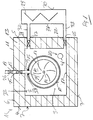
- the device shown in Fig. 1 in a vertical section for the preparation of dishes comprises an oven 1.
- This Furnace 1 can have a practically cuboid housing 2, in which a cooking space 3 is available for the dishes to be prepared is.
- the basic body of the housing 2 comprises two side walls 4 and 5, a top wall 6, a bottom 7 and a rear wall 8. These fixed walls 4 to 8 of the housing 2 and the door have an outer shell 11 and an inner shell 12, which for example made of an impact-resistant material made of metal. Located between these sleeves 11 and 12 heat-insulating material 13 of a known type.
- the door enables loading and unloading of the cooking space 3 Food.
- the door is designed in a manner known per se, that the cooking space 3 can be closed watertight.
- a self-contained strip can do this (not shown) from a resilient material, for example made of rubber, which is located between the Front edges of the furnace walls 4 to 7 and the inside of the door located.
- This strip of material surrounds the one with the door closing opening in the base body of the housing 2, which is limited laterally by the furnace walls 4 to 7 mentioned.
- the strip of material can either be on the door or on the body be attached to the housing 2.
- a closure device (not shown) provided for the door, which of a type known per se and approved in aircraft can.
- the device has a fan 15 (FIGS. 1 and 8), its operation by a control device (not shown) this facility is controllable.
- the control device is advantageously attached to the outside of the rear wall 8 of the housing. However, it can also be arranged outside the furnace his.
- the fan 15 is designed as a turbine wheel, which on the shaft 14 of a drive motor (not shown) is attached.
- the turbine wheel 15 is located in the cooking space 3, while the motor is arranged outside the cooking space 3 is.
- the fan 15 is the rear wall 8 assigned to the furnace 1.
- the shaft 14 goes through an opening 9 (Fig. 8) in the rear wall 8 and the shaft 14 is in the opening 9 of this wall 8 water or stored vapor-tight.
- the engine is on the outside of the back wall 8 attached.
- the wave can also be through another Pass through the wall of the housing 2, e.g. through the top wall 6 of the same.
- the turbine wheel 15 is as close as possible to the Furnace wall arranged.
- the turbine wheel 15 has a disc 16 which on the Drive shaft 14 of the motor is attached centrally. That disc 16 can be embedded in the furnace wall 8.
- the inside of the cooking chamber 3 facing surface of the disc 16 is with Provide blades 17 which protrude axially from the disc 16 and arcuate from the center of the disc 16 towards its edge run. The axially distant from the disc 16 The edges of the blades 17 are with one another by means of a ring 24 connected. (Fig. 8)
- the fan 15 also serves for the circulation of Air and steam (fluid) in the cooking space 3.
- This circulation enables among other things, that the temperature in the cooking space 3 during preparation of food is practically the same everywhere and that the Heat exchange between the fluid and the food in the cooking space 3 is going on intensely.
- At least one heating device is located in the interior 3 of the housing 2 10 or 60, which works with the fan 15.
- the heating device 10 or 60 is on the inside one of the fixed walls 4 to 8 of the main body of the housing 2 arranged. In the case shown is the heater 10 or 60 assigned to the inside of the housing rear wall 8.
- the heating device 10 or 60 is in itself known way to a corresponding energy source on the Control device can be connected and it is useful designed as an electric heater.
- the heater 10 shown in Fig. 1 has essentially the shape of an open ring, which the fan 15 almost completely surrounds in its circumferential direction.
- the opening or the interruption in the ring or in the heating device 10 or 60 is located in the upper area or in the apex area of this, so that here a gap 29 in the heating device 10 or 60 is available. This gap is through the end parts of the heater 10 or 60 laterally limited.
- grommets 58 and 59 In the area of the ends of the open ring 10 are grommets 58 and 59, through which the heating device 10 between 60 connected to the energy source is.
- the Heating device 10 or 60 Viewed parallel to the longitudinal direction of the shaft 14, the Heating device 10 or 60 a dimension or a depth, which with the depth of the fan 15, i.e. with the distance between the disk 16 and the ring 24 of the turbine wheel 15, is comparable. As a result, the fan 15 is off the heater 10 or 60 not only along its circumference but also surrounded along its depth or width. This offers the Advantage that water droplets from the peripheral part of the rotating fan 15 are thrown away on a relatively large surface area of the heating device 10 get into steam and almost instantaneously being transformed.
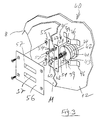
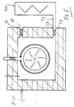
- This heater 60 includes three radiators 61, 62 and 63, each of which is practically the shape of an open one Pentagon.
- In the area of the end parts of each Radiator 61 or 62 or 63 is one the already mentioned spouts 58 and 59, through which the respective Radiator 61 or 62 or 63 connected to the energy source is.
- the end parts of the radiators 61 to 63 run practically perpendicular to the rear wall 8 of the furnace housing 2.
- the respective radiators 61 or 62 or 63 also have a central part 64 or 65 or 66, which is between his End portions 58 and 59 extends and which is practically parallel runs or lies to the wall 8 on which the heating element 61 until 63 is appropriate.
- the end parts of the individual radiators 61 to 63 are different long, so that the middle parts 64, 65 and 66 of the radiators 61 to 63 at different intervals the wall 8 are arranged.
- the lengths of the end parts are in illustrated case selected so that the middle parts 64 to 66 the radiator 61 to 63, viewed in the longitudinal direction of the Wave 14, side by side.
- the end parts of the first radiator 61 is shortest, so that the middle section 64 this heating body 61 is closest to the wall 8.
- the Middle part 66 of the wall 8 is the most distant.
- the diameter of the radiators 61 to 63 is chosen so that the central parts 64 to 66 of the radiators lying side by side 61 to 63 practically the entire width of the turbine wheel 15 cover the same between the disc 16 and the ring 24 or surrounded.
- thermometer 23 of a thermometer is also located in the cooking chamber 3. This thermal sensor 23 is in the example shown in arranged in the upper region of the cooking space 3. The executive committee of the thermometer sensor 23 goes through in the example shown the top wall 6 and it is to the control device also connected.
- the pipe section 18 can be arranged such that the inside of the cooking chamber 3 lying the same against one the components of the furnace 1 is directed, which from the supplied water can form fog and / or steam. If the Pipe piece mouth is directed towards the turbine wheel 15, then water, which is in the form of jets or bullets through the feed line 18 into the cooking chamber 3, through which rotating turbine wheel 15 first converted into fog. This The turbine wheel 15 mists the heater 10 or 60 hurled where the mist turned into steam becomes. If the pipe section 18 against the radiator 10 or 60th is directed, then the injected water converted directly to steam.
- one of the walls of the housing 2 extend two further pipe sections 21 and 22, which are open into cooking space 3 on one side and towards the outside on the other.
- the pipe sections 21 and 22 in one of the vertical side walls 5 of the furnace housing 2.
- these pipe sections 21 and 22 can also be in the rear wall 8 of the furnace housing 2 are.
- One of these pipe sections 21 is located at the top near the top wall 6 of the housing 2.
- the other pipe section 22 is located in the area of the inner shell at the bottom 12 of the bottom 7 of the housing 2.
- a check valve 27 is arranged, the operation of the control device is controllable.
- a further check valve 28 is arranged, the Operation can also be controlled by the control device is.
- the present device also includes a capacitor 30 for steam which is generated in the cooking space 3.
- Fig. 2 shows this Condenser 30 in an exploded view.
- the Capacitor 30 is the outside of the case shown associated side wall 5 of the furnace housing 2 assigned.
- the condenser 30 can, however, also the outside of the rear wall 8 of the Housing 2 may be assigned.
- As such means 69 come plates Ribs, etc., which are inside the capacitor 30 in are arranged in a suitable manner. From the furnace 1 facing The side wall 31 of the capacitor 30 has lines 32 and 33, which are attached to the pipe sections 21 and 22 in the other Housing 2 of the furnace 1 are connected in a steam-tight manner.
- This exhaust 35 On the outside of said capacitor wall 31 is a Exhaust 35 arranged.
- This exhaust 35 has a pipe section 36 on which is attached to the outside of the capacitor wall 31 is.
- the lower end of this pipe section 36 goes through the Sidewall 31 and it opens into the interior of the capacitor 30 in the area of the lower part of the capacitor 30.
- the upper end of the exhaust pipe 36 is spongy Insulating piece 34, which the existing mouth of the Exhaust pipe 36 covers.
- This end part of the exhaust pipe 36 is with two opposing, resilient tabs 37th and 38 provided which the insulating piece 34 against the mouth of the Press exhaust pipe 36 and which also a replacement allow the insulation piece 34.
- a cooling device can be arranged, which follows is described.
- a safety valve 40 of the present facility in an explosive Representation shown In the inner shell 12 one of the walls of the housing 2, in the case shown this is the inner shell 12 of the rear wall 8, an opening 41 is made, which has a circular contour in the case shown. This Opening 41 is associated with a valve seat 42, which is is located on the outside of the shell 12 and which is shown in the Case is annular.
- This seat 42 is a valve body 43 opposite, which is the shape of a disc or Pot with a low circulation wall 44 or similar can. The end part of the peripheral wall 44 or the edge part of the Disc lie on the valve seat 42 sealingly, if that Valve 40 is closed.
- the valve arrangement 40 further comprises means 45 which are used for Guiding the valve body 43 with respect to the valve seat 42 serve.
- These means 45 comprise two spacers 46, which are located next to the valve seat 42 and which ones of this valve seat 42 lie diametrically opposite one another.
- the Distance between the end faces 39 facing away from the casing 12 Spacers 46 is greater than the distance between the rear Surface 58 of the valve body 43 from the shell 12.
- Means 45 also includes a tab 47 which is so long is that it bridges the distance between the spacers 46 can.
- the respective end part of this tab 47 is open the end face 39 one of the spacers 46 attached.
- in the middle area of the tab 47 is an opening or bore 48 executed, which with a threaded bore 49 in the middle Area of the rear wall 58 of the valve body 43 is aligned.
- a screw 50 is provided which passes through the middle Opening 48 passes through the tab 47 and the bolt in the threaded bore 49 is screwed into the valve body 43.
- a coil spring 51 surrounds the threaded bolt of the screw 50. One end of this spring 51 is on the inside of the Tab 47 and the other end of the spring 51 lies on the rear wall 58 of the valve body 43. The spring 51 thus presses the Valve body 43 away from the tab 47 and thus against the valve seat 42 on.
- the screw head 52 has two sections 53 and 54, which follow each other in the longitudinal direction of the screw 50.
- the first or outer head section 53 has a larger one Diameter than the second or inner screw portion 54.
- the diameter of the first head section 53 is larger than the diameter of the central opening 48 in the tab 47. As a result, this first head portion 53 can pass through the tab opening 48 do not go through.
- This head section 53 is located on the outside of the tab 47.
- the perimeter this first head portion 53 may be shaped as a hexagon his.
- the second head section 54 has a cylindrical outer surface, whose diameter is such that this head section 54 pass through the central opening 48 in the tab 47 can.
- the length of this second head section 54 is at least as large as the stroke of the valve body 43. If the pressure in the cooking space 3 rises such that the size of the Contact force of the coil spring 51 exceeds, then the Valve body 43 pushed away from valve seat 42. It moves the second head section 54 in the tab opening 48 accordingly in the longitudinal direction of the screw 50.
- This second Head section 54 works together with coil spring 51 as a guide of the valve body 43.
- This valve arrangement 40 is essentially between the sleeves 11 and 12 of the housing wall.
- a corresponding and larger opening 55 executed, which the assembly and maintenance work of the valve assembly 40 in the Enclosure wall enables.
- This outer opening 55 is with the help a cover 56, in which slots 57 are made are. Through these slots 57, steam, etc. from the Housing 2 escape after valve 40 has opened.
- This Valve assembly 40 can also be attached to the door of furnace 1 his.
- the control device is designed so that it works together of the individual components of this facility based on one stored in this control device Program can control.
- the control device can also an arrangement for determining time intervals, i.e. a Clock or a clock generator included.
- This batchwise water supply is by the successive in the pipe section 18 or 19
- Throttle valves 25 and 26 controlled these valves 25 and 26 can be controlled alternately by the control device. This means that one of the valves 25 and 26 the amount of supplied water controls while the other valve is fully open is. This can be done during a predetermined first time period Z1 expire, this first time period Z1 for example Lasts 1 minute.
- second Time period Z2 which coincides with the following minute can, the roles of the valves 25 and 26 by the Control device interchanged, so that valve that is full was open, now controls the water supply. The other valve is fully open during this second period Z2.
- valves 25 and 26 are for security reasons. Because if you would only use one of the valves 25 or 26 and if this valve should not close, then the cooking space would 3 fill with water. This water could then come from the Drain cooking space 3 and water damage in the area of the Arrange the oven after opening the door of the cooking space 3 is. If you contrast two valves 25 and 26 in the described Used wisely, then it breaks properly working valve water supply.
- the control of the amount of water introduced into the cooking space 3 takes place by successive opening and closing of the valve 25 or 26 controlling the water supply in each case controlling valve is through the control device after expiration a predetermined waiting time W during a short time window F opened.
- the valve can, for example, after expiration a waiting time W of 3 to 10 seconds during a time window F remain open for 50 milliseconds. This is causing Ingress of water into the cooking space 3, which occurs during a time window F last, for example, 50 milliseconds, where between two successive shots of water Waiting time W is 3 to 10 milliseconds.
- the temperature in the cooking space 3 is during the second operating section T2 at a predetermined value by alternating Switched on and off the radiator 10 or 60 held.
- the Fan 15 ensures that the fluid circulates in the cooking space 3 and is evenly distributed so that the thermal energy the food is fed intensively.
- the temperature in the oven 3 lies above during this operating section T2 85 degrees Celsius. Therefore, the injected one evaporates Amount of water immediately. This causes the moisture in the cooking space 3 elevated.
- the control device ends the water ingress Closing the throttle valves 25 and 26 in the pipe section 18 or 19th
- This second working or operating section T2 ends when the overpressure in the cooking space 3, which is due to the development of the Steam was caused at the heating device 10 or 60, have been reduced by condensation of the steam in the condenser 30 is.
- the length of this second operating section is T2 especially by the amount of food in the cooking space 3 and by determines the temperature of the food to be cooked as it enters the cooking space 3 has been filled. These circumstances can help in determining the length of this second operating section T2 through the Control device are taken into account. Hence one needs no measurement of pressure in the cooking space in the present method 3rd
- the last section of the present procedure which for example, can take 30 seconds, no water more injected into the cooking space 3. Then the steam outlet valve 27 opened in the upper line 32, so that steam condensed to water from the cooking chamber 3 in the condenser 30.
- the Capacitor 30 can also act as a collector for the Condensation can be considered.
- FIG. 4 shows a further possible embodiment of the present Facility.
- This device shows instead of a connection to a water pipe a container 20 for receiving from water to.
- This container 20 is above the furnace 1 arranged.
- At the bottom of the container 20 is the line piece 19 connected at one end.
- the other end of this line section 19 is connected to the outer end of the pipe section 18, causing water from the container 20 by its own weight, can flow into the cooking space 3 if the Throttle valves 25 and 26 are continuous.
- the container 20 can be designed as a removable container.
- Such a Container 20 can be outside the installation area of the furnace 1 be filled with water.
- a furnace 1 designed in this way can Water supply network on board an aircraft, for example operated independently.
- FIG. 5 shows yet another embodiment of the present Device in which the steam outlet valve in the steam supply pipe 21 to the capacitor 30 is eliminated.
- the internal flow resistance in the condenser 30 be relatively high so that the fluid from the cooking space 3 cannot easily escape into the capacitor 30.
- This particular one Execution of the capacitor 30 is with another Symbol indicated, which for the internal structure of the capacitor 30 in Fig. 5 is used.
- the embodiment of the present device shown in FIG. 6 differs from the versions described above especially in that the steam supply pipe 32 is eliminated is.
- the capacitor 30 is on the housing 2 of the open 1 therefore only via the water discharge pipe described above 33 connected.
- In the lower pipe section 22 is controllable Valve 28 arranged in the manner described above.
- In the Upper pipe section 21 is the safety valve described above 40 housed.
- FIG. 7 shows still another embodiment of the present Device which of the in connection with Fig. 6 Execution runs out and in which even the valve 28th in the lower pipe section 22 is omitted.
- this facility must the cross section of the pipe section 22 and / or the line 33, however be smaller than in the foregoing present facility. This is because of an overload of the capacitor 30 by supplying an excessive amount of To protect steam. Basically, the bigger the volume of the cooking space 3, the smaller the cross section of the tubes 22 and 33, respectively.
- Cooling device 70 are.
- This cooling device 70 is in the illustrated case as a battery composed of elements which can generate cold. So-called Peltier elements are used which cover the top wall 71 of the Form the capacitor housing. As is well known, Peltier elements produce heat at one end and cold at the other. In the battery, the Peltier elements are arranged so that their "Cold” ends are inside the capacitor 30. On this The "cold" end of steam condenses into water faster than if it were there is no cooling battery.
- the "hot” ends of the Peltier elements are on the outside the ceiling 71 of the capacitor housing 72.
- cooling fins 73 can end these ends of the Peltier elements 71 be assigned.
- this Capacitor 30 has an opening 74 through which Air can escape.
Landscapes
- Engineering & Computer Science (AREA)
- Chemical & Material Sciences (AREA)
- Combustion & Propulsion (AREA)
- Mechanical Engineering (AREA)
- General Engineering & Computer Science (AREA)
- Food Science & Technology (AREA)
- Commercial Cooking Devices (AREA)
- Cookers (AREA)
- Meat, Egg Or Seafood Products (AREA)
- General Preparation And Processing Of Foods (AREA)
Applications Claiming Priority (2)
| Application Number | Priority Date | Filing Date | Title |
|---|---|---|---|
| CH258698 | 1998-12-30 | ||
| CH258698 | 1998-12-30 |
Publications (3)
| Publication Number | Publication Date |
|---|---|
| EP1016832A2 true EP1016832A2 (fr) | 2000-07-05 |
| EP1016832A3 EP1016832A3 (fr) | 2001-11-07 |
| EP1016832B1 EP1016832B1 (fr) | 2004-09-15 |
Family
ID=4237124
Family Applications (1)
| Application Number | Title | Priority Date | Filing Date |
|---|---|---|---|
| EP99811202A Expired - Lifetime EP1016832B1 (fr) | 1998-12-30 | 1999-12-23 | Procédé et appareil de préparation de repas |
Country Status (4)
| Country | Link |
|---|---|
| US (1) | US6342262B1 (fr) |
| EP (1) | EP1016832B1 (fr) |
| AT (1) | ATE276490T1 (fr) |
| DE (1) | DE59910511D1 (fr) |
Cited By (8)
| Publication number | Priority date | Publication date | Assignee | Title |
|---|---|---|---|---|
| NL1023507C2 (nl) * | 2003-05-23 | 2004-11-24 | Konink Fabriek Inventum B V | Oven en combinatie daarvan met een stoommodule. |
| CH699876A1 (de) * | 2008-11-13 | 2010-05-14 | Kuhn Rikon Ag | Gerät zum Dampfgaren von Nahrungsmitteln. |
| US7829825B2 (en) | 2003-05-23 | 2010-11-09 | Koninklijke Fabriek Inventum B.V. | Oven and its combination with a steam module |
| WO2011058075A3 (fr) * | 2009-11-12 | 2011-10-06 | Airbus Operations Gmbh | Appareil de cuisine pour aéronef |
| US8288690B2 (en) | 2009-01-16 | 2012-10-16 | Mag Aerospace Industries, Inc. | Oven steam generator systems and methods |
| US11027052B2 (en) | 2017-11-22 | 2021-06-08 | HDL Therapuetics, Inc. | Systems and methods for priming fluid circuits of a plasma processing system |
| US11033582B1 (en) | 2017-12-28 | 2021-06-15 | Hdl Therapeutics, Inc. | Methods for preserving and administering pre-beta high density lipoprotein having a predetermined minimum level of degradation |
| US20220003426A1 (en) * | 2020-03-10 | 2022-01-06 | Koninklijke Fabriek Inventum B.V. | Water Drip Collector for Steam Generation |
Families Citing this family (28)
| Publication number | Priority date | Publication date | Assignee | Title |
|---|---|---|---|---|
| FR2839546B1 (fr) * | 2002-05-07 | 2006-09-22 | Premark Feg Llc | Four pour la cuisson d'aliments |
| NL1024564C2 (nl) * | 2003-10-17 | 2005-04-20 | Konink Fabriek Inventum B V | Oven, in het bijzonder voor toepassing in een vliegtuig, met een door een gelijkstroommotor aangedreven ventilator. |
| US20060112947A1 (en) * | 2004-11-29 | 2006-06-01 | Atul Saksena | Steam cooker with moving steam delivery member |
| EP1684018A1 (fr) * | 2004-12-30 | 2006-07-26 | Filippi S.r.l. | Four à la vapeur avec un filtre accessible pour la pierre à chaux et un réservoir pour l'eau chargé avec un traite étanche |
| US20060251785A1 (en) | 2005-05-06 | 2006-11-09 | Stefania Fraccon | Method for cooking food using steam |
| US7745763B2 (en) | 2005-07-11 | 2010-06-29 | Whirlpool Corporation | Method for baking bread using steam |
| US20180049590A1 (en) * | 2016-04-29 | 2018-02-22 | Alan Backus | Devices and methods for supporting and preparing foods |
| US20170311757A1 (en) * | 2016-04-29 | 2017-11-02 | Alan Backus | Devices and methods for supporting and preparing foods |
| US20070062927A1 (en) * | 2005-09-06 | 2007-03-22 | Sells Joel M | Steam generator system for a household oven |
| US20070175884A1 (en) * | 2006-01-31 | 2007-08-02 | Atul Saksena | Steam cooker with steam delivery device |
| EP2040003A1 (fr) * | 2006-07-10 | 2009-03-25 | Panasonic Corporation | Appareil de cuisson par chauffage |
| US7867534B2 (en) * | 2006-10-18 | 2011-01-11 | Whirlpool Corporation | Cooking appliance with steam generator |
| ITMO20060354A1 (it) * | 2006-11-03 | 2008-05-04 | Angelo Grandi Cucine Spa | Apparato di cottura |
| US20090136640A1 (en) * | 2007-11-26 | 2009-05-28 | Whirlpool Corporation | Method for Baking a Casserole Using Steam |
| US8207477B2 (en) | 2007-11-26 | 2012-06-26 | Whirlpool Corporation | Method for cooking vegetables using steam |
| AU2016204889B2 (en) * | 2008-01-28 | 2017-11-16 | Duke Manufacturing Co. | Convection oven |
| CN102771523B (zh) * | 2008-01-28 | 2015-04-22 | 杜克制造公司 | 对流式炉 |
| JP2010210118A (ja) * | 2009-03-09 | 2010-09-24 | Jamco Corp | 漏水防止用安全弁を備えた旅客機搭載用スチームオーブン |
| JP4707758B2 (ja) * | 2009-10-08 | 2011-06-22 | シャープ株式会社 | 蒸気発生ユニットおよびそれを用いた蒸気調理器 |
| RU2531415C2 (ru) * | 2010-04-28 | 2014-10-20 | Шарп Кабусики Кайся | Варочное устройство |
| SG192750A1 (en) * | 2011-02-15 | 2013-09-30 | Duke Mfg Co | Holding oven |
| CA2867153C (fr) * | 2012-03-28 | 2017-01-24 | Siebe Schootstra | Four de vehicule ayant un injecteur de vapeur d'eau optimise |
| US20160116171A1 (en) * | 2014-10-22 | 2016-04-28 | General Electric Company | Oven airflow control |
| DE102016215650A1 (de) * | 2016-08-19 | 2018-02-22 | BSH Hausgeräte GmbH | Haushaltsgargerät |
| US11771099B2 (en) * | 2018-06-25 | 2023-10-03 | Blues Hog Llc | Smoking apparatus and methods |
| EP4018892A1 (fr) * | 2020-12-22 | 2022-06-29 | Koninklijke Philips N.V. | Appareil de cuisson |
| CN116919188A (zh) * | 2022-03-31 | 2023-10-24 | 广东美的生活电器制造有限公司 | 蒸汽空气炸锅 |
| USD1104595S1 (en) | 2023-06-09 | 2025-12-09 | Duke Manufacturing Co. | Food holding cabinet |
Family Cites Families (7)
| Publication number | Priority date | Publication date | Assignee | Title |
|---|---|---|---|---|
| FR2619613B1 (fr) * | 1987-08-18 | 1989-11-24 | Grandi Rene | Dispositif d'unite de cuisson par introduction modulable de vapeur fluante avec chemin preferentiel a surchauffeurs et couloir de condensation des vapeurs residuelles |
| CH677582A5 (fr) * | 1989-08-03 | 1991-06-14 | Wuest Ernst Menu System | |
| US5410951A (en) * | 1992-05-26 | 1995-05-02 | The Laitram Corporation | Apparatus and method for continuous high-volume steam cooking |
| US5595109A (en) * | 1994-05-31 | 1997-01-21 | Carton Drive Enterprises | Food storage device with dehumidification means |
| US5619983A (en) * | 1995-05-05 | 1997-04-15 | Middleby Marshall, Inc. | Combination convection steamer oven |
| DE19517824B4 (de) * | 1995-05-18 | 2006-05-18 | Wilhelm Fessmann Gmbh U. Co. Kg | Verfahren und Vorrichtung zum Kochen von Fleisch- und Wurstwaren mit Dampf |
| FR2750027B1 (fr) * | 1996-06-21 | 1999-03-05 | Moulinex Sa | Dispositif de condensation de vapeurs de cuisson et appareil de cuisson comportant un tel dispositif |
-
1999
- 1999-12-23 DE DE59910511T patent/DE59910511D1/de not_active Expired - Fee Related
- 1999-12-23 EP EP99811202A patent/EP1016832B1/fr not_active Expired - Lifetime
- 1999-12-23 AT AT99811202T patent/ATE276490T1/de not_active IP Right Cessation
- 1999-12-29 US US09/474,363 patent/US6342262B1/en not_active Expired - Fee Related
Cited By (14)
| Publication number | Priority date | Publication date | Assignee | Title |
|---|---|---|---|---|
| NL1023507C2 (nl) * | 2003-05-23 | 2004-11-24 | Konink Fabriek Inventum B V | Oven en combinatie daarvan met een stoommodule. |
| WO2004104483A1 (fr) * | 2003-05-23 | 2004-12-02 | Koninklijke Fabriek Inventum B.V. | Four et sa combinaison avec un module vapeur |
| US7829825B2 (en) | 2003-05-23 | 2010-11-09 | Koninklijke Fabriek Inventum B.V. | Oven and its combination with a steam module |
| CH699876A1 (de) * | 2008-11-13 | 2010-05-14 | Kuhn Rikon Ag | Gerät zum Dampfgaren von Nahrungsmitteln. |
| WO2010054490A1 (fr) * | 2008-11-13 | 2010-05-20 | Kuhn Rikon Ag | Appareil de cuisson à la vapeur d'aliments |
| US8288690B2 (en) | 2009-01-16 | 2012-10-16 | Mag Aerospace Industries, Inc. | Oven steam generator systems and methods |
| US8581151B2 (en) | 2009-01-16 | 2013-11-12 | Mag Aerospace Industries, Inc. | Steam oven water delivery and drain valve systems and methods |
| WO2011058075A3 (fr) * | 2009-11-12 | 2011-10-06 | Airbus Operations Gmbh | Appareil de cuisine pour aéronef |
| US11027052B2 (en) | 2017-11-22 | 2021-06-08 | HDL Therapuetics, Inc. | Systems and methods for priming fluid circuits of a plasma processing system |
| US11400188B2 (en) | 2017-11-22 | 2022-08-02 | Hdl Therapeutics, Inc. | Systems for removing air from the fluid circuits of a plasma processing system |
| US11033582B1 (en) | 2017-12-28 | 2021-06-15 | Hdl Therapeutics, Inc. | Methods for preserving and administering pre-beta high density lipoprotein having a predetermined minimum level of degradation |
| US11903965B2 (en) | 2017-12-28 | 2024-02-20 | Hdl Therapeutics, Inc. | Methods for preserving and administering pre-beta high density lipoprotein having a predetermined minimum level of degradation |
| US20220003426A1 (en) * | 2020-03-10 | 2022-01-06 | Koninklijke Fabriek Inventum B.V. | Water Drip Collector for Steam Generation |
| US11940157B2 (en) * | 2020-03-10 | 2024-03-26 | Koninklijke Fabriek Inventum B.V. | Water drip collector for steam generation |
Also Published As
| Publication number | Publication date |
|---|---|
| EP1016832B1 (fr) | 2004-09-15 |
| DE59910511D1 (de) | 2004-10-21 |
| ATE276490T1 (de) | 2004-10-15 |
| US6342262B1 (en) | 2002-01-29 |
| EP1016832A3 (fr) | 2001-11-07 |
Similar Documents
| Publication | Publication Date | Title |
|---|---|---|
| EP1016832B1 (fr) | Procédé et appareil de préparation de repas | |
| EP0436703B1 (fr) | Procede et dispositif pour preparer des aliments | |
| DE69409916T2 (de) | Dampfsteuereinrichtung eines Backofens | |
| DE69322503T2 (de) | Heissluftofen zum zubereiten von nahrung in heissluft | |
| DE60114916T2 (de) | Drainagelochstruktur bei einem Ofen mit erzwungener Konvektionsausführung | |
| DE2851671C2 (de) | Dampfkocher | |
| EP3500800B1 (fr) | Appareil de cuisson domestique | |
| DE2306927C3 (de) | Druckkochvorrichtung | |
| DE3700894A1 (de) | Geraet zum garen von nahrungsmitteln und verfahren zum betrieb des geraetes | |
| DE69622316T2 (de) | Anlage und Verfahren zum Sterilisieren mittels feuchter Hitze, insbesondere für Autoclaven zur Verwendung in der Zahnarztpraxis | |
| EP1108384B1 (fr) | Appareil domestique pour cuire à vapeur sous pression atmosphérique | |
| DE69202187T2 (de) | Dampfkochgerät für Nahrungsmittel. | |
| DE2541374A1 (de) | Garmachverfahren und -vorrichtung | |
| DE69919268T2 (de) | Ofen mit Heissluftumwälzung | |
| DE60117267T2 (de) | Verfahren und vorrichtung zur thermischen behandelung ungeschaelter eier | |
| DE102018004617A1 (de) | Gewürzbeschwadungssystem zum Einsatz in Dampfgargeräten und Konvektomaten mit in sich abgeschlossenem Garraum | |
| DE60116849T2 (de) | Dampfauslass für Dampfkochgeräte | |
| EP1855058B1 (fr) | Procédé et appareil de cuisson de plats à la vapeur | |
| DE3010253A1 (de) | Mikrowellen-kochherd | |
| EP1010384A1 (fr) | Appareil de cuisson et méthode pour réchauffer un produit de cuisson à l'aide de vapeur | |
| DE4333585C2 (de) | Herd mit einem als Backrohr nutzbaren, elektrisch oder mittels Gas beheizbaren Backraum | |
| DE29500595U1 (de) | Backofen mit einem einen Gebläsebrenner aufweisenden Dampferzeuger | |
| DE2644839A1 (de) | Luftzirkulationsofen | |
| DE3206348A1 (de) | Trockenkammer fuer holz | |
| DE19720736C2 (de) | Gerät zum Garen von Nahrungsmitteln |
Legal Events
| Date | Code | Title | Description |
|---|---|---|---|
| PUAI | Public reference made under article 153(3) epc to a published international application that has entered the european phase |
Free format text: ORIGINAL CODE: 0009012 |
|
| AK | Designated contracting states |
Kind code of ref document: A2 Designated state(s): AT BE CH CY DE DK ES FI FR GB GR IE IT LI LU MC NL PT SE |
|
| AX | Request for extension of the european patent |
Free format text: AL;LT;LV;MK;RO;SI |
|
| PUAL | Search report despatched |
Free format text: ORIGINAL CODE: 0009013 |
|
| AK | Designated contracting states |
Kind code of ref document: A3 Designated state(s): AT BE CH CY DE DK ES FI FR GB GR IE IT LI LU MC NL PT SE |
|
| AX | Request for extension of the european patent |
Free format text: AL;LT;LV;MK;RO;SI |
|
| 17P | Request for examination filed |
Effective date: 20020405 |
|
| AKX | Designation fees paid |
Free format text: AT BE CH CY DE DK ES FI FR GB GR IE IT LI LU MC NL PT SE |
|
| 17Q | First examination report despatched |
Effective date: 20030812 |
|
| GRAP | Despatch of communication of intention to grant a patent |
Free format text: ORIGINAL CODE: EPIDOSNIGR1 |
|
| GRAS | Grant fee paid |
Free format text: ORIGINAL CODE: EPIDOSNIGR3 |
|
| GRAA | (expected) grant |
Free format text: ORIGINAL CODE: 0009210 |
|
| RIN1 | Information on inventor provided before grant (corrected) |
Inventor name: WUEST, ERNST |
|
| AK | Designated contracting states |
Kind code of ref document: B1 Designated state(s): AT BE CH CY DE DK ES FI FR GB GR IE IT LI LU MC NL PT SE |
|
| PG25 | Lapsed in a contracting state [announced via postgrant information from national office to epo] |
Ref country code: IT Free format text: LAPSE BECAUSE OF FAILURE TO SUBMIT A TRANSLATION OF THE DESCRIPTION OR TO PAY THE FEE WITHIN THE PRE;WARNING: LAPSES OF ITALIAN PATENTS WITH EFFECTIVE DATE BEFORE 2007 MAY HAVE OCCURRED AT ANY TIME BEFORE 2007. THE CORRECT EFFECTIVE DATE MAY BE DIFFERENT FROM THE ONE RECORDED.SCRIBED TIME-LIMIT Effective date: 20040915 Ref country code: IE Free format text: LAPSE BECAUSE OF FAILURE TO SUBMIT A TRANSLATION OF THE DESCRIPTION OR TO PAY THE FEE WITHIN THE PRESCRIBED TIME-LIMIT Effective date: 20040915 Ref country code: FI Free format text: LAPSE BECAUSE OF FAILURE TO SUBMIT A TRANSLATION OF THE DESCRIPTION OR TO PAY THE FEE WITHIN THE PRESCRIBED TIME-LIMIT Effective date: 20040915 Ref country code: CY Free format text: LAPSE BECAUSE OF FAILURE TO SUBMIT A TRANSLATION OF THE DESCRIPTION OR TO PAY THE FEE WITHIN THE PRESCRIBED TIME-LIMIT Effective date: 20040915 |
|
| REG | Reference to a national code |
Ref country code: GB Ref legal event code: FG4D Free format text: NOT ENGLISH Ref country code: CH Ref legal event code: EP |
|
| REG | Reference to a national code |
Ref country code: CH Ref legal event code: NV Representative=s name: PATENTANWALTSBUERO DIPL.-ING. S. V. KULHAVY + CO. |
|
| REG | Reference to a national code |
Ref country code: IE Ref legal event code: FG4D Free format text: GERMAN |
|
| REF | Corresponds to: |
Ref document number: 59910511 Country of ref document: DE Date of ref document: 20041021 Kind code of ref document: P |
|
| PG25 | Lapsed in a contracting state [announced via postgrant information from national office to epo] |
Ref country code: SE Free format text: LAPSE BECAUSE OF FAILURE TO SUBMIT A TRANSLATION OF THE DESCRIPTION OR TO PAY THE FEE WITHIN THE PRESCRIBED TIME-LIMIT Effective date: 20041215 Ref country code: GR Free format text: LAPSE BECAUSE OF FAILURE TO SUBMIT A TRANSLATION OF THE DESCRIPTION OR TO PAY THE FEE WITHIN THE PRESCRIBED TIME-LIMIT Effective date: 20041215 Ref country code: DK Free format text: LAPSE BECAUSE OF FAILURE TO SUBMIT A TRANSLATION OF THE DESCRIPTION OR TO PAY THE FEE WITHIN THE PRESCRIBED TIME-LIMIT Effective date: 20041215 |
|
| PGFP | Annual fee paid to national office [announced via postgrant information from national office to epo] |
Ref country code: GB Payment date: 20041222 Year of fee payment: 6 |
|
| PG25 | Lapsed in a contracting state [announced via postgrant information from national office to epo] |
Ref country code: LU Free format text: LAPSE BECAUSE OF NON-PAYMENT OF DUE FEES Effective date: 20041223 Ref country code: AT Free format text: LAPSE BECAUSE OF NON-PAYMENT OF DUE FEES Effective date: 20041223 |
|
| PGFP | Annual fee paid to national office [announced via postgrant information from national office to epo] |
Ref country code: DE Payment date: 20041223 Year of fee payment: 6 |
|
| PG25 | Lapsed in a contracting state [announced via postgrant information from national office to epo] |
Ref country code: ES Free format text: LAPSE BECAUSE OF FAILURE TO SUBMIT A TRANSLATION OF THE DESCRIPTION OR TO PAY THE FEE WITHIN THE PRESCRIBED TIME-LIMIT Effective date: 20041226 |
|
| PGFP | Annual fee paid to national office [announced via postgrant information from national office to epo] |
Ref country code: FR Payment date: 20041227 Year of fee payment: 6 |
|
| PG25 | Lapsed in a contracting state [announced via postgrant information from national office to epo] |
Ref country code: MC Free format text: LAPSE BECAUSE OF NON-PAYMENT OF DUE FEES Effective date: 20041231 Ref country code: BE Free format text: LAPSE BECAUSE OF NON-PAYMENT OF DUE FEES Effective date: 20041231 |
|
| PGFP | Annual fee paid to national office [announced via postgrant information from national office to epo] |
Ref country code: NL Payment date: 20041231 Year of fee payment: 6 |
|
| GBT | Gb: translation of ep patent filed (gb section 77(6)(a)/1977) |
Effective date: 20050126 |
|
| PGFP | Annual fee paid to national office [announced via postgrant information from national office to epo] |
Ref country code: CH Payment date: 20050310 Year of fee payment: 6 |
|
| REG | Reference to a national code |
Ref country code: IE Ref legal event code: FD4D |
|
| BERE | Be: lapsed |
Owner name: MENU SYSTEM A.G. Effective date: 20041231 |
|
| PLBE | No opposition filed within time limit |
Free format text: ORIGINAL CODE: 0009261 |
|
| STAA | Information on the status of an ep patent application or granted ep patent |
Free format text: STATUS: NO OPPOSITION FILED WITHIN TIME LIMIT |
|
| ET | Fr: translation filed | ||
| 26N | No opposition filed |
Effective date: 20050616 |
|
| PG25 | Lapsed in a contracting state [announced via postgrant information from national office to epo] |
Ref country code: GB Free format text: LAPSE BECAUSE OF NON-PAYMENT OF DUE FEES Effective date: 20051223 |
|
| PG25 | Lapsed in a contracting state [announced via postgrant information from national office to epo] |
Ref country code: LI Free format text: LAPSE BECAUSE OF NON-PAYMENT OF DUE FEES Effective date: 20051231 Ref country code: CH Free format text: LAPSE BECAUSE OF NON-PAYMENT OF DUE FEES Effective date: 20051231 |
|
| PG25 | Lapsed in a contracting state [announced via postgrant information from national office to epo] |
Ref country code: NL Free format text: LAPSE BECAUSE OF NON-PAYMENT OF DUE FEES Effective date: 20060701 Ref country code: DE Free format text: LAPSE BECAUSE OF NON-PAYMENT OF DUE FEES Effective date: 20060701 |
|
| REG | Reference to a national code |
Ref country code: CH Ref legal event code: PL |
|
| GBPC | Gb: european patent ceased through non-payment of renewal fee |
Effective date: 20051223 |
|
| PG25 | Lapsed in a contracting state [announced via postgrant information from national office to epo] |
Ref country code: FR Free format text: LAPSE BECAUSE OF NON-PAYMENT OF DUE FEES Effective date: 20060831 |
|
| NLV4 | Nl: lapsed or anulled due to non-payment of the annual fee |
Effective date: 20060701 |
|
| REG | Reference to a national code |
Ref country code: FR Ref legal event code: ST Effective date: 20060831 |
|
| BERE | Be: lapsed |
Owner name: *MENU SYSTEM A.G. Effective date: 20041231 |
|
| PG25 | Lapsed in a contracting state [announced via postgrant information from national office to epo] |
Ref country code: PT Free format text: LAPSE BECAUSE OF NON-PAYMENT OF DUE FEES Effective date: 20050215 |