EP1016887A1 - Dichtes-gedämpftes Faseroptischesbündel und hieraus aufgebautes optisches Faserkabel - Google Patents
Dichtes-gedämpftes Faseroptischesbündel und hieraus aufgebautes optisches Faserkabel Download PDFInfo
- Publication number
- EP1016887A1 EP1016887A1 EP99403328A EP99403328A EP1016887A1 EP 1016887 A1 EP1016887 A1 EP 1016887A1 EP 99403328 A EP99403328 A EP 99403328A EP 99403328 A EP99403328 A EP 99403328A EP 1016887 A1 EP1016887 A1 EP 1016887A1
- Authority
- EP
- European Patent Office
- Prior art keywords
- optical fiber
- tight
- buffered
- optical fibers
- coated
- Prior art date
- Legal status (The legal status is an assumption and is not a legal conclusion. Google has not performed a legal analysis and makes no representation as to the accuracy of the status listed.)
- Withdrawn
Links
Images


Classifications
-
- G—PHYSICS
- G02—OPTICS
- G02B—OPTICAL ELEMENTS, SYSTEMS OR APPARATUS
- G02B6/00—Light guides; Structural details of arrangements comprising light guides and other optical elements, e.g. couplings
- G02B6/44—Mechanical structures for providing tensile strength and external protection for fibres, e.g. optical transmission cables
- G02B6/4401—Optical cables
- G02B6/441—Optical cables built up from sub-bundles
- G02B6/4411—Matrix structure
-
- G—PHYSICS
- G02—OPTICS
- G02B—OPTICAL ELEMENTS, SYSTEMS OR APPARATUS
- G02B6/00—Light guides; Structural details of arrangements comprising light guides and other optical elements, e.g. couplings
- G02B6/44—Mechanical structures for providing tensile strength and external protection for fibres, e.g. optical transmission cables
- G02B6/4401—Optical cables
- G02B6/4403—Optical cables with ribbon structure
- G02B6/4404—Multi-podded
-
- G—PHYSICS
- G02—OPTICS
- G02B—OPTICAL ELEMENTS, SYSTEMS OR APPARATUS
- G02B6/00—Light guides; Structural details of arrangements comprising light guides and other optical elements, e.g. couplings
- G02B6/44—Mechanical structures for providing tensile strength and external protection for fibres, e.g. optical transmission cables
- G02B6/4401—Optical cables
- G02B6/4407—Optical cables with internal fluted support member
- G02B6/4408—Groove structures in support members to decrease or harmonise transmission losses in ribbon cables
-
- G—PHYSICS
- G02—OPTICS
- G02B—OPTICAL ELEMENTS, SYSTEMS OR APPARATUS
- G02B6/00—Light guides; Structural details of arrangements comprising light guides and other optical elements, e.g. couplings
- G02B6/44—Mechanical structures for providing tensile strength and external protection for fibres, e.g. optical transmission cables
- G02B6/4401—Optical cables
- G02B6/441—Optical cables built up from sub-bundles
- G02B6/4413—Helical structure
Definitions
- the present invention relates to a tight-buffered optical fiber bundle for manufacturing an optical fiber cable for indoor use, and more particularly relates to a tight-buffered optical fiber bundle and an optical fiber cable composed of the same which can diverge the respective optical fibers by means of necks formed between the adjacent optical fibers by coating the plural optical fibers integrally.
- optical fiber cables are to be divided into out door cables and indoor cables in general according to the installation place.
- the indoor cable applied in a short distance or in a building, is considerably lighter and weaker than the outdoor cable.
- the emerging multimedia access network especially an optical access network installed in a limited duct space like an intelligent building requires multi-core optical cables having smaller diameter. To meet this requirement, it is recommended to apply a ribbon type cable rather than a loose tube strand cable, since the ribbon type cable has 30% or more increase of fiber density with better additive properties compared to the loose tube strand cable.
- the conventional ribbon type cables as disclosed in the U.S. Patent No. 4,752,112, U.S. Patent No. 5,457,762, U.S. Patent No. 5,761,363, etc., are formed by coating integrally plural optical fibers arranged in a row by a coated layer and a jacket. That is, since the ribbon type cable is manufactured through the processes of bundling and coating again after first coating each optical fiber, it makes the outer diameter of the ribbon type cable large and decreases its productivity as well.
- the present invention is directed to a tight-buffered optical fiber bundle and a multi-core optical fiber cable composed of the same that substantially obviates one or more of the problems, limitations, and disadvantages of the related art.
- a tight-buffered optical fiber bundle in accordance with an embodiment of the invention comprising: a plurality of optical fibers disposed in a low and spaced apart from each other; and a coated layer for coating the plural optical fibers untegrally so as to provide a plurality of necks in a longitudinal direction between the adjacent optical fibers, thus diverging the respective coated optical fibers easily following the necks.
- the optical fibers have no coated layer or have a relatively thin coated layer.
- a tight-buffered optical fiber bundle in accordance with another embodiment of the invention comprising: a plurality of optical fibers disposed in a low and spaced apart from each other; and a coated layer for coating the plural optical fibers integrally so as to form a plurality of connecting parts in a longitudinal direction between the adjacent optical fibers, thus diverging the respective coated optical fibers easily following the connecting part.
- the optical fibers have no coated layer or have a relatively thin coated layer.
- the distance of the adjacent optical fibers is larger than the thickness of the coated layer.
- an optical fiber cable composed of a tight-buffered optical fiber bundle in accordance with another embodiment of the invention comprising: a tight-buffered optical fiber bundle including a plurality of optical fibers integrally coated in a row so as to form a plurality of necks between the adjacent optical fibers in a longitudinal direction; an auxiliary strength member arranged on outer circumference of the tight-buffered optical fiber bundle; and a jacket coated on outer circumference of the auxiliary strength member.
- an optical fiber cable composed of a tight-buffered optical fiber bundle in accordance with another embodiment of tire invention comprising: a plurality of tight-buffered optical fiber bundles arranged in lattice arrangement integrally so as to form at least two necks between a plurality of optical fibers disposed in a low and spaced apart from each other; an auxiliary strength member arranged on outer circumference of the tight-buffered optical fiber bundles coated in lattice arrangement; and a jacket coated on outer circumference of the auxiliary strength member.
- the optical fibers have no coated layer or have a relatively thin coated layer.
- a multi-core optical fiber cable composed of tight-buffered optical fiber bundles in accordance with another embodiment of the invention comprising: a central strength member; a plurality of loose tubes arranged spirally on outer circumference of the central strength member; a plurality of tignt-buffered optical fiber bundles inserted and piled up in the loose tubes; and a plurality of coated layers for coating outer circumference of the loose tubes.
- a multi-core optical fiber cable composed of tight-buffered optical fiber bundles in accordance with another embodiment of the invention comprising: a multi-slot rod, wherein a central strength member is laid, having a plurality of slots; a plurality of tight-buffered optical fiber bundles inserted and piled up in the slots; and a plurality of coated layers for coating the outer circumference of the multi-slot rod.
- a multi-core optical fiber cable composed of tight-buffered optical fiber bundles in accordance with another embodiment of the invention comprising: a circular rod, wherein a central strength member is laid; a plurality of tight-buffered optical fiber bundles of lattice arrangement disposed fast onto outer circumference of the circular rod spirally; a plurality of fillers inserted into gaps between the plural tight-buffered optical fiber bundles of lattice arrangement; an auxiliary strength member arranged on outer circumference of the tight-buffered optical fiber bundles of lattice arrangement; and a jacket coated on outer circumference of the auxiliary strength member.
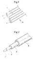
- a tight-buffered optical fiber bundle 10 is composed of integrally coated plural optical fibers 1 arranged in a row.
- a coated layer 5 is formed with PVC, nylon havirc elasticity and flexibility for preventing microbending.
- the conventional optical fiber 2 is composed of an optical fiber and a coated layer 4. Accordingly, it is necessary to add a separate process for coating again over the coated layer 4.
- the present invention facilitates manufacturing the ribbon type cable 10 by only process for coating the plural optical fiber 1 integrally. More specially, the present invention increases productivity since the plural optical fibers having no coated layer are coated integrally at a time.
- the present invention facilitates diverging the respective optical fibers 1 by providing necks 7 between the adjacent optical fibers 1.
- the necks 7 are very important to accomplish the substantial objects of the present invention. Accordingly, since the present invention facilitates diverging the optical fibers without any special tools, it increases operation efficiency in working fields.
- the present invention uses flexible materials such as thermoplastic elastomer, soft PVC, nylon, etc., which makes it possible to tear the respective optical fibers 1 very easily. Therefore, the ribbon type cable in accordance with the present invention is suitable for the indoor use. That is, since the indoor optical cable should be bent easily, he outdoor optical cable having hard coated layers is not suitable for the indoor use. Because the outdoor optical cable is formed with thin and hard coated layers, it may be cut very easily.
- the tight-buffered optical fiber bundle 10 according to the present invention includes plural optical fibers 1 which are not broken easily as the coated layer 5 is made of relatively thick with soft materials. For example, whereas the thickness of the coated layer of the conventional ribbon type cable is approximately 0.35mm, that of the present invention is desired to be up to maximum 0.9mm.
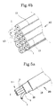
- the tight-buffered optical fiber bundle 10 comprises connecting parts 13 between the plural optical fibers 1 arranged in a row. Accordingly, it is easier to separate the respective optical fibers 1 by means of the connecting parts 13 than the necks 7. Furthermore, when each notch 15 is provided in the middle of the connecting parts 13 in the longitudinal direction, it is easier to separate the optical fibers 1 following the notch 15.
- a tight-buffered optical fiber bundle of lattice arrangement is formed in a overall rectangular shape by connecting each optical fiber 1 through more than two necks 7. That is, according to the present invention, there is no need to pile up the plural ribbon-type cables in the conventional multi-core optical fiber cable. Besides, the present invention increases productivity by coating the plural optical fibers 1 by means of one compressor at a time. As shown in Fig. 4b, each optical fiber 1 is joined with one another through more than two connecting part 13. Besides, it is desired tc provide the notches 15 between the respective adjacent connecting parts 13.
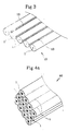
- the tight-buffered optical fiber bundles 10 and 40 include plural optical fibers 1 arranged in a row or in lattice, it is easy to manufacture the indoor cables only by coating an auxiliary strength member 16 and a jacket 18. Accordingly, it is easier and simpler to manufacture the indoor optical cable in accordance with the present invention than the conventional optical cable. That is, it is difficult and takes long time to manufacture the conventional indoor optical cable as the plural optical fibers are stranded spirally on the outer circumference of the central strength member. Furthermore, it needs a large working space to install pay-off machines for supplying the respective optical fibers. However, it is possible to manufacture the indoor optical cable just by arranging a predetermined coated layer on the outer circumference of the tight-buffered optical fiber bundles in accordance with the present invention without stranding the respective optical fibers.
- the tight-buffered optical fiber bundles in accordance with the present invention are suitable for manufacturing the multi-core optical fiber cable for indoor use.
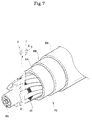
- a plurality of loose tubes 63 include the tight-buffered optical fiber bundles 10 and 40 according to the present inventicr are installed spirally on outer circumference of a central strength member 64. Then, the outer circumference of the loose tubes is coated with predetermined coated layers 64, 66 and 68, thus completing the multi-core optical fiber cable 60 composed of tight-buffered optical fiber bundles for indoor use.
- a multi-core optical fiber cable composed of tight-buffered optical fiber bundles is shown in Fig. 7.
- tight-buffered optical fiber bundles 10 and 40 of the invention are inserted into a plurality of slots in a multi-slot rod 67 wherein the central strength member 65 is laid, then predetermined coated layers 64, 66 and 68 are applied on the outer circumference.
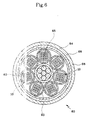
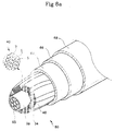
- the tight-buffered optical fiber bundle 40 of lattice arrangement comprises a plurality of optical fibers 1 piled up in rectangular shape. That is, as shown in Fig. 8a and 8b, after install the tight-buffered optical fiber bundles 10 and 40 of the invention spirally on outer circumference of a circular rod 69 wherein the central strength member 65 is laid, fillers 35 are inserted into gaps between the adjacent tight-buffered optical fiber bundles 40. Then, predetermined coated layers 64, 66 and 68 are applied on the outer circumference of the tight-buffered optical fiber bundles 40 the fillers 35, thus completing the multi-core optical fiber cables 80 for indoor use.
- the fillers 35 are made of aramid fibers having high tension strength.
- the coated layers of the multi-core optical fiber cable 80 include a water-proof layer 64 coated with water-proof tape, a metal coated layer 66 on outer circumference of the water-proof layer 64 for buffering external impact, and a jacket of polyethylene 68 on exterior layer.
- the multi-core optical fiber cable 40 composed of tight-buffered optical fiber bundles of lattice arrangement according to the present invention can decrease manufacturing cost sharply since it doesn't apply the multi-slot rod or grooves. Besides, it can save manufacturing time and space, since it needs a minimum pay-off machines supplying ribbon-type optical fibers. Furthermore, the multi-core optical fiber cable 40 composed of tight-buffered optical fiber bundles having the lattice arrangement can increase fiber density since it is possible to install.as much optical fibers as the thickness of grooves in the conventional optical fiber cable.
- the multi-core optical fiber cable of 19mm in diameter according to the present invention contains 144 fibers, and its fiber density is 0.508core/mm 2 .
Landscapes
- Physics & Mathematics (AREA)
- General Physics & Mathematics (AREA)
- Optics & Photonics (AREA)
- Optical Fibers, Optical Fiber Cores, And Optical Fiber Bundles (AREA)
- Light Guides In General And Applications Therefor (AREA)
Applications Claiming Priority (8)
| Application Number | Priority Date | Filing Date | Title |
|---|---|---|---|
| KR1019980063887A KR100342592B1 (ko) | 1998-12-31 | 1998-12-31 | 타이트바운드형광케이블 |
| KR2019980028677U KR20000015278U (ko) | 1998-12-31 | 1998-12-31 | 타이트 바운드형 초다심 광케이블 |
| KR9863905 | 1998-12-31 | ||
| KR9863879 | 1998-12-31 | ||
| KR9828677 | 1998-12-31 | ||
| KR1019980063905A KR20000047141A (ko) | 1998-12-31 | 1998-12-31 | 광케이블 |
| KR1019980063879A KR20000047115A (ko) | 1998-12-31 | 1998-12-31 | 타이트 바운드형 광케이블 |
| KR9863887 | 1998-12-31 |
Publications (1)
| Publication Number | Publication Date |
|---|---|
| EP1016887A1 true EP1016887A1 (de) | 2000-07-05 |
Family
ID=27483301
Family Applications (1)
| Application Number | Title | Priority Date | Filing Date |
|---|---|---|---|
| EP99403328A Withdrawn EP1016887A1 (de) | 1998-12-31 | 1999-12-31 | Dichtes-gedämpftes Faseroptischesbündel und hieraus aufgebautes optisches Faserkabel |
Country Status (3)
| Country | Link |
|---|---|
| EP (1) | EP1016887A1 (de) |
| JP (1) | JP2000206382A (de) |
| CN (1) | CN1259677A (de) |
Cited By (2)
| Publication number | Priority date | Publication date | Assignee | Title |
|---|---|---|---|---|
| WO2009120959A1 (en) * | 2008-03-28 | 2009-10-01 | Adc Telecommunications, Inc. | Multi-fiber fiber optic cable |
| US7664354B2 (en) | 2006-08-01 | 2010-02-16 | Nexans | System and method for loose tube tight buffer indoor/outdoor optical fiber cable |
Families Citing this family (9)
| Publication number | Priority date | Publication date | Assignee | Title |
|---|---|---|---|---|
| US6539151B2 (en) | 2000-08-21 | 2003-03-25 | Corning, Incorporated | Method for making separable multiple core optical fibers, the resulting fiber structures, and uses thereof |
| WO2004042446A1 (en) | 2002-11-06 | 2004-05-21 | Sumitomo Electric Industries, Ltd. | Optical fiber ribbon and optical fiber cable using the same |
| JP3664254B2 (ja) * | 2002-11-06 | 2005-06-22 | 住友電気工業株式会社 | 光ファイバテープ心線及びその製造方法 |
| FI120471B (fi) * | 2005-02-23 | 2009-10-30 | Liekki Oy | Optisen kuidun käsittelymenetelmä |
| US7194168B2 (en) * | 2005-03-03 | 2007-03-20 | Nexans | Tight buffer optical fiber ribbon |
| JP2011232733A (ja) * | 2010-04-07 | 2011-11-17 | Sumitomo Electric Ind Ltd | 光ファイバテープ心線、光ファイバケーブル、及び光ファイバテープ心線の製造方法 |
| CN116256838B (zh) * | 2023-02-21 | 2025-10-10 | 长飞光纤光缆股份有限公司 | 一种带状光单元、光缆及其制备方法 |
| CN117038192B (zh) * | 2023-10-10 | 2023-12-12 | 江苏永鼎股份有限公司 | 一种可扩展的光电综合缆 |
| EP4579304A1 (de) | 2023-12-27 | 2025-07-02 | Sterlite Technologies Limited | Faseroptisches kabel mit einer fest gepufferten multifasereinheit |
Citations (7)
| Publication number | Priority date | Publication date | Assignee | Title |
|---|---|---|---|---|
| DE1245162B (de) * | 1964-11-07 | 1967-07-20 | Saale Glas G M B H | Mehrfachfaser fuer Lichtleitzwecke aus thermoplastischen Werkstoffen, insbesondere aus Glas |
| EP0429238A2 (de) * | 1989-11-13 | 1991-05-29 | Minnesota Mining And Manufacturing Company | Selbsttragender Lichtleitfaserwickel und Verfahren zu dessen Herstellung |
| DE4211488A1 (de) * | 1992-04-06 | 1993-10-07 | Siemens Ag | Optisches Kabel mit Bandleitungen |
| US5531064A (en) * | 1994-06-03 | 1996-07-02 | Fujikura Ltd. | Optical fiber cable containing ribbon fibers |
| EP0874261A2 (de) * | 1997-04-21 | 1998-10-28 | Lucent Technologies Inc. | Kabel hoher Dichte für Steigleitung und Deckenzwischenraum und für den Innen- und Aussengebrauch |
| EP0886157A2 (de) * | 1997-06-18 | 1998-12-23 | Nippon Telegraph and Telephone Corporation | Optisches Kabel und optisches Bandkabel |
| WO1999028776A1 (en) * | 1997-11-27 | 1999-06-10 | Koninklijke Kpn N.V. | Cable having optical-fibre ribbons |
-
1999
- 1999-12-31 EP EP99403328A patent/EP1016887A1/de not_active Withdrawn
-
2000
- 2000-01-03 CN CN00100870A patent/CN1259677A/zh active Pending
- 2000-01-04 JP JP158A patent/JP2000206382A/ja active Pending
Patent Citations (7)
| Publication number | Priority date | Publication date | Assignee | Title |
|---|---|---|---|---|
| DE1245162B (de) * | 1964-11-07 | 1967-07-20 | Saale Glas G M B H | Mehrfachfaser fuer Lichtleitzwecke aus thermoplastischen Werkstoffen, insbesondere aus Glas |
| EP0429238A2 (de) * | 1989-11-13 | 1991-05-29 | Minnesota Mining And Manufacturing Company | Selbsttragender Lichtleitfaserwickel und Verfahren zu dessen Herstellung |
| DE4211488A1 (de) * | 1992-04-06 | 1993-10-07 | Siemens Ag | Optisches Kabel mit Bandleitungen |
| US5531064A (en) * | 1994-06-03 | 1996-07-02 | Fujikura Ltd. | Optical fiber cable containing ribbon fibers |
| EP0874261A2 (de) * | 1997-04-21 | 1998-10-28 | Lucent Technologies Inc. | Kabel hoher Dichte für Steigleitung und Deckenzwischenraum und für den Innen- und Aussengebrauch |
| EP0886157A2 (de) * | 1997-06-18 | 1998-12-23 | Nippon Telegraph and Telephone Corporation | Optisches Kabel und optisches Bandkabel |
| WO1999028776A1 (en) * | 1997-11-27 | 1999-06-10 | Koninklijke Kpn N.V. | Cable having optical-fibre ribbons |
Cited By (3)
| Publication number | Priority date | Publication date | Assignee | Title |
|---|---|---|---|---|
| US7664354B2 (en) | 2006-08-01 | 2010-02-16 | Nexans | System and method for loose tube tight buffer indoor/outdoor optical fiber cable |
| WO2009120959A1 (en) * | 2008-03-28 | 2009-10-01 | Adc Telecommunications, Inc. | Multi-fiber fiber optic cable |
| US8422843B2 (en) | 2008-03-28 | 2013-04-16 | Adc Telecommunications, Inc. | Multi-fiber fiber optic cable |
Also Published As
| Publication number | Publication date |
|---|---|
| CN1259677A (zh) | 2000-07-12 |
| JP2000206382A (ja) | 2000-07-28 |
Similar Documents
| Publication | Publication Date | Title |
|---|---|---|
| US8525031B2 (en) | Low cost, high performance flexible reinforcement for communications cable | |
| EP3879323B1 (de) | Glasfaserkabel | |
| US6229944B1 (en) | Optical fiber cable | |
| US8126303B2 (en) | Low cost, high performance, low profile flexible reinforcement for communications cable | |
| US6836603B1 (en) | Optical fiber cables | |
| US6839494B2 (en) | Dual stage fiber optic cable design | |
| US20060291787A1 (en) | Fiber optic cable having strength component | |
| EP1224496A1 (de) | Faseroptisches anschlusskabel | |
| US10684433B2 (en) | Optical cable and manufacturing method | |
| US20240176088A1 (en) | Optical cable with dielectric strength elements and toneable element | |
| US7435909B2 (en) | Low cost, high performance flexible reinforcement for communications cable | |
| US11852880B2 (en) | Optical fiber cable with movable rip cord | |
| US20230213716A1 (en) | Ribbed and grooved sheath for optical fiber cable | |
| US6845789B2 (en) | High density fiber optic cable inner ducts | |
| US6775445B2 (en) | Optical fiber drop cable | |
| JP2000206382A (ja) | マルチコアタイトバッファ光繊維及びこれを用いた多心光ケ―ブル | |
| EP1024383A1 (de) | Hybride Kabel für Unterfussboden-Verkabelung | |
| JP2005208430A (ja) | 光ケーブル | |
| US20230194817A1 (en) | Optical fiber cable with coil elements | |
| EP3779547B1 (de) | Glasfasterbandkabel | |
| EP0825465B1 (de) | Einadriges elektrisches Kabel mit einem faseroptischen Element | |
| KR102951758B1 (ko) | 토너블 컨덕터 또는 다크 파이버가 수용가능한 컴팩트형 소심 루즈튜브 광케이블 및 이의 제조 방법 | |
| JP2004205979A (ja) | 光ドロップケーブル | |
| KR20000047131A (ko) | 타이트 버퍼형 광섬유 및 그것을 구비한 초다심 광케이블 | |
| JP4388006B2 (ja) | 光ケーブル |
Legal Events
| Date | Code | Title | Description |
|---|---|---|---|
| PUAI | Public reference made under article 153(3) epc to a published international application that has entered the european phase |
Free format text: ORIGINAL CODE: 0009012 |
|
| AK | Designated contracting states |
Kind code of ref document: A1 Designated state(s): AT BE CH CY DE DK ES FI FR GB GR IE IT LI LU MC NL PT SE |
|
| AX | Request for extension of the european patent |
Free format text: AL;LT;LV;MK;RO;SI |
|
| 17P | Request for examination filed |
Effective date: 20010105 |
|
| AKX | Designation fees paid |
Free format text: AT BE CH CY DE DK ES FI FR GB GR IE IT LI LU MC NL PT SE |
|
| STAA | Information on the status of an ep patent application or granted ep patent |
Free format text: STATUS: THE APPLICATION IS DEEMED TO BE WITHDRAWN |
|
| 18D | Application deemed to be withdrawn |
Effective date: 20020701 |