EP1016908A2 - Zweiteilige Spule mit Flanschen - Google Patents
Zweiteilige Spule mit Flanschen Download PDFInfo
- Publication number
- EP1016908A2 EP1016908A2 EP99204439A EP99204439A EP1016908A2 EP 1016908 A2 EP1016908 A2 EP 1016908A2 EP 99204439 A EP99204439 A EP 99204439A EP 99204439 A EP99204439 A EP 99204439A EP 1016908 A2 EP1016908 A2 EP 1016908A2
- Authority
- EP
- European Patent Office
- Prior art keywords
- spool
- facing surface
- inwardly facing
- flange
- web material
- Prior art date
- Legal status (The legal status is an assumption and is not a legal conclusion. Google has not performed a legal analysis and makes no representation as to the accuracy of the status listed.)
- Withdrawn
Links
Images




Classifications
-
- B—PERFORMING OPERATIONS; TRANSPORTING
- B65—CONVEYING; PACKING; STORING; HANDLING THIN OR FILAMENTARY MATERIAL
- B65H—HANDLING THIN OR FILAMENTARY MATERIAL, e.g. SHEETS, WEBS, CABLES
- B65H75/00—Storing webs, tapes, or filamentary material, e.g. on reels
- B65H75/02—Cores, formers, supports, or holders for coiled, wound, or folded material, e.g. reels, spindles, bobbins, cop tubes, cans, mandrels or chucks
- B65H75/04—Kinds or types
- B65H75/08—Kinds or types of circular or polygonal cross-section
- B65H75/14—Kinds or types of circular or polygonal cross-section with two end flanges
-
- B—PERFORMING OPERATIONS; TRANSPORTING
- B29—WORKING OF PLASTICS; WORKING OF SUBSTANCES IN A PLASTIC STATE IN GENERAL
- B29C—SHAPING OR JOINING OF PLASTICS; SHAPING OF MATERIAL IN A PLASTIC STATE, NOT OTHERWISE PROVIDED FOR; AFTER-TREATMENT OF THE SHAPED PRODUCTS, e.g. REPAIRING
- B29C45/00—Injection moulding, i.e. forcing the required volume of moulding material through a nozzle into a closed mould; Apparatus therefor
- B29C45/0025—Preventing defects on the moulded article, e.g. weld lines, shrinkage marks
-
- B—PERFORMING OPERATIONS; TRANSPORTING
- B29—WORKING OF PLASTICS; WORKING OF SUBSTANCES IN A PLASTIC STATE IN GENERAL
- B29C—SHAPING OR JOINING OF PLASTICS; SHAPING OF MATERIAL IN A PLASTIC STATE, NOT OTHERWISE PROVIDED FOR; AFTER-TREATMENT OF THE SHAPED PRODUCTS, e.g. REPAIRING
- B29C45/00—Injection moulding, i.e. forcing the required volume of moulding material through a nozzle into a closed mould; Apparatus therefor
- B29C45/17—Component parts, details or accessories; Auxiliary operations
- B29C45/26—Moulds
-
- G—PHYSICS
- G03—PHOTOGRAPHY; CINEMATOGRAPHY; ANALOGOUS TECHNIQUES USING WAVES OTHER THAN OPTICAL WAVES; ELECTROGRAPHY; HOLOGRAPHY
- G03C—PHOTOSENSITIVE MATERIALS FOR PHOTOGRAPHIC PURPOSES; PHOTOGRAPHIC PROCESSES, e.g. CINE, X-RAY, COLOUR, STEREO-PHOTOGRAPHIC PROCESSES; AUXILIARY PROCESSES IN PHOTOGRAPHY
- G03C3/00—Packages of films for inserting into cameras, e.g. roll-films, film-packs; Wrapping materials for light-sensitive plates, films or papers, e.g. materials characterised by the use of special dyes, printing inks, adhesives
-
- B—PERFORMING OPERATIONS; TRANSPORTING
- B65—CONVEYING; PACKING; STORING; HANDLING THIN OR FILAMENTARY MATERIAL
- B65H—HANDLING THIN OR FILAMENTARY MATERIAL, e.g. SHEETS, WEBS, CABLES
- B65H2701/00—Handled material; Storage means
- B65H2701/50—Storage means for webs, tapes, or filamentary material
- B65H2701/51—Cores or reels characterised by the material
- B65H2701/513—Cores or reels characterised by the material assembled mainly from rigid elements of the same kind
- B65H2701/5136—Moulded plastic elements
-
- G—PHYSICS
- G11—INFORMATION STORAGE
- G11B—INFORMATION STORAGE BASED ON RELATIVE MOVEMENT BETWEEN RECORD CARRIER AND TRANSDUCER
- G11B23/00—Record carriers not specific to the method of recording or reproducing; Accessories, e.g. containers, specially adapted for co-operation with the recording or reproducing apparatus ; Intermediate mediums; Apparatus or processes specially adapted for their manufacture
- G11B23/02—Containers; Storing means both adapted to cooperate with the recording or reproducing means
- G11B23/037—Single reels or spools
Definitions
- the present invention relates generally to a spool, such as may be used to support a length of web material, particularly photographic web material or other light sensitive material.
- the present invention is more particularly directed to a spool formed from a plastic material and including a flange having a smooth, substantially blemish free surface on an inwardly facing surface.
- Spools have been used to support various materials such as wire, threads, and yarns.
- US Patent Nos. 2,190,013 ( Byers ), 3,334,841 ( Burhop ) relate to spools for supporting wire.
- US Patent No. 4,406,422 ( Philips ) relates to a spool supporting threads and yarns.
- Spools have also been used to support web material, for example, photographic web material or other light sensitive material.
- the spool has a cylindrical portion onto which the web material is wound, and may further include a flange disposed at each end of the cylindrical portion to provide protection for the web material and to provide guidance for the edges of the web material during winding/unwinding.
- Figure 1 shows a spool 10 having a core 12 and a pair of flanges 14,16 disposed at opposite ends of core 12. Web material W is wound between the flanges.
- a light shielding material e.g., an opaque material
- an opaque material wound about the light-sensitive material can form a roll package which provides a light shield for the light-sensitive material.
- the opaque material may restrict the ingress of light between the edges of the convolutions of the wound light-sensitive material.
- the roll package would be light-tight and could therefore be loaded/unloaded into a cooperating apparatus (e.g., a camera) in a white-light environment without adverse affects to the wound light-sensitive material.
- a roll package includes an opaque leader 20 disposed at one end of the web material, and a trailer 22 disposed at the other end of the web material, with the trailer being attached to spool 10. Accordingly, when web material W is wound about spool 10 between end flanges 14,16, first the trailer is wound, then the web material is wound, with the leader being wound about the web material.
- a roll packaging configuration i.e., trailer/web/leader
- Such a roll packaging configuration is available in a type of film package generally referred as a 220 format film package.
- a backing material 24 i.e., a light shielding material
- the width of backing material 24 is greater than the width of the web material.
- the length of backing material is greater than the length of the web material such that an extending portion 25 (herein after referred to as leader L) of backing material 24 extends beyond the length of the web material.
- the backing material may be attached to one end of the web material. Accordingly, when the web material and backing material are wound onto the spool between the end flanges, the wound convolutions alternate between the web material and backing material.
- a roll package in yet a further roll packaging configuration (not shown), includes an opaque leader disposed at one end of the web material, and the other end of the web material being attached to the spool. Accordingly, when the web material W is wound about the spool between the end flanges, first the web material is wound, with the leader being wound about the web material to form a light-tight roll package.
- An object of the present invention is to provide a spool for supporting web material.
- Another object of the present invention is to provide such a spool which promotes the shielding of light sensitive web material from light.
- Still another object of the present invention is to provide such a spool which includes flanges free of imperfections and blemishes
- Yet another object of the present invention is to provide such a spool which is readily manufacturable from a plastic material by means of injection molding.
- the present invention provides a spool having a pair of flanges.
- An inwardly facing surface of each flange includes a substantially blemish free planar surface.
- the edges of the light shielding material are held in intimate contact with the substantially blemish free planar portion. Accordingly, the cooperation between the light shielding material and the substantially planar portion of the flanges forms a light seal barrier.
- a spool having such a substantially blemish free planar surface is manufacturable by means of injection molding.
- a spool comprised of a pair of complementary spool members.
- Each spool member includes a cylindrical portion and a flange having an inwardly facing surface and an outwardly facing surface.
- the spool member is made of a plastic material and is formed by an injection molding process such that the inwardly facing surface of each spool member is formed against a unitary mold component of an injection mold whereby the inwardly facing surface is substantially free of imperfections and blemishes.
- a spool for supporting a length of photosensitive web material.
- the spool is comprised of a pair of complementary spool members formed of a plastic material by an injection molding process.
- Each of the spool members includes a cylindrical portion and a flange with the flange having an outer edge and an inwardly facing surface.
- Each inwardly facing surface includes a substantially planar area adjacent the outer edge which has a surface roughness of less than 25 microinches.
- a roll package includes a spool, a length of web material wound about the spool, and a length of a light-shielding material wound about the wound length of web material.
- the spool is comprised of a pair of complementary spool members formed of a plastic material by an injection molding process.
- Each of the spool members includes a cylindrical portion and a flange with the flange having an outer edge and an inwardly facing surface.
- Each inwardly facing surface includes a substantially planar area adjacent the outer edge having a surface roughness of less than 25 microinches.
- a method of making a spool member having a cylindrical portion and a flange having an inwardly facing surface includes providing a mold cavity; injecting molten plastic material into the mold cavity; forming the inwardly facing surface against a unitary mold component of the mold cavity; and ejecting the molded spool in a direction normal to the inwardly facing surface.
- the present invention provides a spool for supporting web material.
- the spool includes a pair of flanges free of imperfections, whereby an interaction between the flanges and a light shielding material (e.g., a leader or interleaving material) forms a light-tight seal.
- a light shielding material e.g., a leader or interleaving material
- the spool is configured such that it is readily manufacturable from a plastic material by means of injection molding.
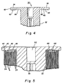
- a spool 30 has a cylindrical core 32 and a flange disposed at opposite ends of the core.
- a flange 34 is shown.
- Each flange includes an outwardly facing surface 36 and an inwardly facing surface 38.
- Inwardly facing surface 38 of each flange includes a substantially planar outer portion 40 adjacent an outer edge 42 of the flange.
- Each inwardly facing surface 38 further includes a recessed portion 44 inboard of outer portion 40. Recessed portion 44 is defined by a transitional area 46 and an inner area 48. The outer portions of the two flanges form annular opposed surfaces.
- 120 format film package includes backing material 24 disposed on one side of web material W along the entire length of the web material.
- the length of backing material 24 is greater than the length of the web material such that the extending portion (herein after referred to as leader L) of the backing material extends beyond the length of the web material.
- An extending portion may also be located at the other end of backing material (i.e., adjacent the spool), referred to as trailer T, to provide protection for the web material when the web material is wound after exposure in a cooperating apparatus.
- a central slot 50 is generally provided to facilitate attachment of trailer T to core 32 at the start of the formation process.
- a drive socket 52 is provided to allow spool 30 to be rotationally driven by a cooperating drive apparatus during winding.
- the width of backing material 24 is less than the distance between the recessed portions of the two flanges.
- convolutions of alternating web material and backing material 24 are wound about core 32 within inner area 48 and then transitional area 46. Note that the width of web material W is less than the width of the distance between the recessed portions of the two flanges, and also less than the width of backing material 24.
- a plurality of convolutions 54 of leader L of backing material 24 are further wound about core 32.
- the edges of the backing material of these convolutions are abutting outer portion 40.
- An interference of the backing material with outer portion 40 could result in a slight bending (or upturn) of the edges of the backing material against outer portion 40. Accordingly, the backing material and the outer portion of the flanges attempt to form a light-tight seal, thereby preventing light from exposing the enclosed light sensitive web material.
- Applicants have discovered that light may be able to penetrate into the roll package. That is, a light-tight seal may not be formed between the edges of the backing material and the outer portion 40.
- Applicants have unexpectedly discovered that blemishes or imperfections on outer portion 40 adversely affect the formation of a light-tight seal between the edges of the backing material and the flange.
- Applicants' experimentation revealed that a surface roughness of greater than 25 microinches may result in a non-light-tight seal. Accordingly, Applicants desire a minimal surface roughness of less than 25 microinches, preferably less than 15 microinches, to provide a suitable light-tight seal.
- Spool 30 is commonly formed of a plastic material by the process known as injection molding. A cavity is formed within substantial metal plates, and molten plastic is injected into this cavity under extreme pressure. After a period of time, in which the molten plastic cools and solidifies, the metal plates are moved apart, to allow the spool to be ejected.
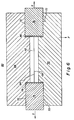
- Figure 6 shows a cross sectional view of the portions of an injection mold 60 which forms a typical cavity 62 for the manufacture of spool 30.
- Parting surface 64 of a stationary plate 66, and a parting surface 68 of moveable plate 70 abut each other, and each have machined from them a volume, representing one-half of the volume of spool 30, oriented such that the axis of the spool volume is coincident with parting surfaces 64, 68.
- Stationary plate 66 and moveable plate 70 also have machined from them semi-cylindrical volumes 72 adjacent each end of cavity 62.
- Semi-cylindrical volumes 72 receive side-draws 74,76 having respective end faces 78,80, whereby end faces 78,80 form opposite ends of cavity 62.
- injection mold 60 After injecting cavity 62 with molten plastic material, and allowing sufficient time for the plastic material to cool and solidify, injection mold 60 is opened by withdrawing moveable plate 70 and side-draws 74,76 in the direction of F in Figure 6, while simultaneously slidably moving side-draws 74,76, relative to moveable plate 70, as depicted by arrows S in Figure 6.
- the open position of injection mold 60 with molded spool 30 ready for ejection is illustrated in Figure 7.
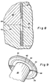
- spools produced in this manner may be generally suitable for use in the manufacture of rolled films, as noted above Applicants have determined that imperfections or blemishes in the surfaces of the flanges of such spools, particularly in outer portion 40, may impair the intimacy of contact between the edges of the outer convolutions of backing material 24 and outer portion 40 of spool 30, thereby allowing some light to reach the light sensitive web material. Such imperfections may be caused by a mismatch between the mold cavity halves wherein the surfaces of stationary plate 66, which form inwardly facing surfaces 38 of spool 30, do not precisely align with the corresponding surfaces of moveable plate 70.
- This mismatch 82 may be caused by errors in the machining of the half volumes into each plate or by the misalignment of stationary plate 66 and moveable plate 70 when mold 60 is closed.
- Figure 9 depicts a spool flange 34 with a step 84 caused by a mismatch between cavity halves.
- FIG. 10 illustrates a spool flange with flash 86 caused by the wear of these edges.
- FIGS 12-14 illustrate a spool 100 in accordance with the present invention.
- Spool 100 comprises two substantially similar and complementary spool members 112,114.
- Each spool member 112,114 includes a flange 116 having an outwardly facing surface 118 and an inwardly facing surface 120.
- Inwardly facing surface 120 of each flange includes an outer portion 122 adjacent an outer edge 124 of the flange.
- Each inwardly facing surface 120 further includes a recessed portion 126 inboard of outer portion 122.
- Recessed portion 126 is defined by a transitional area 128 and an inner area 130.
- Formed within each spool member 112,114 on outwardly facing surface 118 is a drive socket 131 generally provided for mechanical cooperation with a cooperating apparatus (not shown) to rotate spool 100.
- Each spool member 112,114 further includes a cylindrical core portion 132 adjacent flange 116. Extending from one end of cylindrical core portion, opposite the end having flange 116, is an engagement member 134 comprising an extending portion 136 and a locking portion 138. Locking portion 138 includes a chamfered end 135, a projection 137, and surfaces 139. Formed within each cylindrical core portion 132, opposite engagement member 134, is an axially arranged groove 140 having groove edges 141. An open end 142 of groove 140 is chamfered 144. Disposed within cylindrical core portion 132 along groove 140 at an end opposite open end 142, is a bore 146 configured to receive locking portion 138. Also formed within each cylindrical core portion 132 is a slot 148. A surface 150 adjacent groove 140 and slot 148 forms a mechanical stop, as will become more apparent.
- Spool 100 is assembled by inserting projection 137 of locking portion 138 into groove 140 of the other spool member, and slideably moving the spool members relative to the other in the direction shown by arrows S in Figure 13.
- Extending portions 136 flex and deflect whereby locking portion 138 slides along groove 140 of the other spool member until open end 142 of one spool member abuts stop surface 150 of the other spool member.
- a radial force illustrated in Figure 12 by the arrow R, is applied to urge shoulders 152 of locking portion 138 into engagement with edges 154 of bore 146, whereby locking portion 138 is received within bore 146.
- chamfered end 135 of locking portion 138 cooperates with chamfered end 144 of groove 140 to deflect extending portion 136 of engagement member 134. Such deflection provides for the displacement of the locking portion 138 such that locking portion surfaces 139 slide along groove edges 141 until locking portion 138 is received by bore 146.
- the distance from stop surface 150 to shoulders 152 of the locking portion may be slightly greater than the distance between open end 142 and edges 154 of bore 146. If slightly greater, locking portion 138 will freely drop into bore 146. However, with such a configuration, axial movement may occur between the two spool members, with the axial movement being substantially equal to the difference between the two distances.
- the distance from stop surface 150 to shoulders 152 of the locking portion is slightly less than the distance between open end 142 and edges 155 of bore 146. If slightly less, locking portion 138 must be forced into (i.e., snapped) bore 146 of the other spool member, thereby promoting the abutment of open end 142 of one spool member with stop surface 150 of the other spool member. Also, if slightly less, no axial movement between the spool members occurs in the assembled configuration thereby promoting a consistent spacing between the opposed surface of outer portions 122 of inwardly facing surfaces 120 of the flanges.
- a contiguous cylindrical core is formed to support the web material and the light-shielding material.
- an outer surface 154 of locking portion 138 forms a portion of this contiguous cylindrical core.
- a central slot 156 is formed by slots 148 to provide to facilitate attachment of the web material or light-shielding material onto spool 100.
- Spool 100 can be disassembled by removing the locking portions from the bore and slidably moving the spool members relative to the other in the direction opposite that shown by arrows S in Figure 13.
- Spool 100 of the present invention can be manufactured using injection molding.
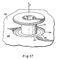
- Figures 15-17 illustrate an injection mold 160 suitable for manufacturing spool members 112,114 in accordance with the present invention.
- a parting surface 162 of a stationary plate 164 abuts a parting surface 166 of a movable plate 168.
- the abutment of slide faces 180,182 forms a portion of cavity 184 defining a portion of the spool member.
- cavity 184 defining the remaining portion of the spool member is formed within stationary plate 164 and moveable plate 168.
- a plastic material is injected into cavity 184 by means known to those skilled in the art to form a spool member 112,114 in accordance with the present invention.
- Spool 100 formed using injection mold 160 shown in Figures 15-17 will be substantially imperfection and blemish free on inwardly facing surface 120 of a flange 116.
- Such imperfections and blemishes are not present since the portion of cavity 184 which forms the inwardly facing surface of the flange (i.e., an outer forming surface 186, a transition forming surface 188, and an inner forming surface 190 of cavity 184 as shown in Figure 17) is formed in its entirety within the unitary movable plate 168.
- no injection mold parting line is formed on the inwardly facing surface.
- spool members 112,114 may provide for an imperfection and blemish free inwardly facing surface of the flange.
- spool members may be identical, those skilled in the art will recognize that spool members 112,114 need not be identical to provide such an imperfection and blemish free inwardly facing surface of the flange.
Landscapes
- Engineering & Computer Science (AREA)
- Manufacturing & Machinery (AREA)
- Mechanical Engineering (AREA)
- Microelectronics & Electronic Packaging (AREA)
- Physics & Mathematics (AREA)
- General Physics & Mathematics (AREA)
- Moulds For Moulding Plastics Or The Like (AREA)
- Injection Moulding Of Plastics Or The Like (AREA)
- Details Of Cameras Including Film Mechanisms (AREA)
- Storage Of Web-Like Or Filamentary Materials (AREA)
- Storing, Repeated Paying-Out, And Re-Storing Of Elongated Articles (AREA)
Applications Claiming Priority (2)
| Application Number | Priority Date | Filing Date | Title |
|---|---|---|---|
| US22447998A | 1998-12-31 | 1998-12-31 | |
| US224479 | 1998-12-31 |
Publications (2)
| Publication Number | Publication Date |
|---|---|
| EP1016908A2 true EP1016908A2 (de) | 2000-07-05 |
| EP1016908A3 EP1016908A3 (de) | 2001-02-07 |
Family
ID=22840884
Family Applications (1)
| Application Number | Title | Priority Date | Filing Date |
|---|---|---|---|
| EP99204439A Withdrawn EP1016908A3 (de) | 1998-12-31 | 1999-12-21 | Zweiteilige Spule mit Flanschen |
Country Status (2)
| Country | Link |
|---|---|
| EP (1) | EP1016908A3 (de) |
| JP (1) | JP2000198626A (de) |
Cited By (2)
| Publication number | Priority date | Publication date | Assignee | Title |
|---|---|---|---|---|
| EP1391782A1 (de) * | 2002-08-19 | 2004-02-25 | Konica Corporation | Lichtabschirmender Flansch |
| CN117163420A (zh) * | 2023-11-01 | 2023-12-05 | 江苏永银化纤有限公司 | 一种化纤制造用收卷打包装置 |
Families Citing this family (3)
| Publication number | Priority date | Publication date | Assignee | Title |
|---|---|---|---|---|
| JP2002274759A (ja) * | 2001-03-15 | 2002-09-25 | Furukawa Electric Co Ltd:The | テープ状体巻取ボビン |
| KR101156511B1 (ko) * | 2009-11-06 | 2012-06-18 | 비아이 이엠티 주식회사 | 테이프 권취릴 |
| DE102018132484A1 (de) * | 2018-12-17 | 2020-06-18 | Saurer Technologies GmbH & Co. KG | Spinnspulenträger für eine Zwirnmaschine |
Family Cites Families (3)
| Publication number | Priority date | Publication date | Assignee | Title |
|---|---|---|---|---|
| US3635421A (en) * | 1969-11-20 | 1972-01-18 | Western Electric Co | Spool assemblies |
| US4068808A (en) * | 1977-02-16 | 1978-01-17 | King Richard J | Two part plastic reel |
| DE69621158T2 (de) * | 1995-09-13 | 2002-09-05 | Fuji Photo Film Co. Ltd., Minamiashigara | Fotografische Filmrolle |
-
1999
- 1999-11-01 JP JP11310985A patent/JP2000198626A/ja active Pending
- 1999-12-21 EP EP99204439A patent/EP1016908A3/de not_active Withdrawn
Cited By (4)
| Publication number | Priority date | Publication date | Assignee | Title |
|---|---|---|---|---|
| EP1391782A1 (de) * | 2002-08-19 | 2004-02-25 | Konica Corporation | Lichtabschirmender Flansch |
| US6942096B2 (en) | 2002-08-19 | 2005-09-13 | Konica Corporation | Light shielding flange |
| CN117163420A (zh) * | 2023-11-01 | 2023-12-05 | 江苏永银化纤有限公司 | 一种化纤制造用收卷打包装置 |
| CN117163420B (zh) * | 2023-11-01 | 2023-12-26 | 江苏永银化纤有限公司 | 一种化纤制造用收卷打包装置 |
Also Published As
| Publication number | Publication date |
|---|---|
| JP2000198626A (ja) | 2000-07-18 |
| EP1016908A3 (de) | 2001-02-07 |
Similar Documents
| Publication | Publication Date | Title |
|---|---|---|
| US4848693A (en) | Film cassette | |
| US3934842A (en) | Minicassette for recording tape | |
| US7347397B2 (en) | Reel and recording tape cartridge | |
| US4938429A (en) | Film cassette | |
| JPS5827586B2 (ja) | ジキテ−プヨウ ノ ツミカサネカノウナ マキトリシン | |
| US5040739A (en) | Film-thrusting cassette | |
| EP1016908A2 (de) | Zweiteilige Spule mit Flanschen | |
| US4244535A (en) | Separable film spool and method of loading film cassette therewith | |
| US5364042A (en) | Spool adapter | |
| CA1312060C (en) | Light-tight cassette and method for packing rolls of light-sensitive material in a cassette | |
| US7690594B2 (en) | Recording tape cartridge | |
| US3243490A (en) | Method and apparatus for molding in one-piece a spool, winding core, or the like | |
| US5211348A (en) | Photographic film cassette | |
| US6283745B1 (en) | Injection mold for producing spool | |
| US5265821A (en) | Photographic film cassette | |
| US5251841A (en) | Photographic film cassette | |
| US5282585A (en) | Photographic film cassette | |
| US5031855A (en) | Film-thrusting cassette | |
| US6938851B2 (en) | Tape path roller guide and method for making | |
| US3768747A (en) | Cartridge takeup core and core-mounting system | |
| EP1191533A1 (de) | Magnetbandkassette, kassettenteil,giessverfahren, markierungsverfahren für gegossenes produkt sowie gegossenes produkt | |
| GB2362136A (en) | Thermal transfer tape cassette with winding cores having play such that neither the winding cores nor the tape contact the cassette housing during spooling | |
| JPH0542434Y2 (de) | ||
| US5950026A (en) | Roll stabilized, nesting vee, magnetic head assembly for magnetics-on-film | |
| US5277376A (en) | Photographic film cassette |
Legal Events
| Date | Code | Title | Description |
|---|---|---|---|
| PUAI | Public reference made under article 153(3) epc to a published international application that has entered the european phase |
Free format text: ORIGINAL CODE: 0009012 |
|
| AK | Designated contracting states |
Kind code of ref document: A2 Designated state(s): AT BE CH CY DE DK ES FI FR GB GR IE IT LI LU MC NL PT SE |
|
| AX | Request for extension of the european patent |
Free format text: AL;LT;LV;MK;RO;SI |
|
| PUAL | Search report despatched |
Free format text: ORIGINAL CODE: 0009013 |
|
| AK | Designated contracting states |
Kind code of ref document: A3 Designated state(s): AT BE CH CY DE DK ES FI FR GB GR IE IT LI LU MC NL PT SE |
|
| AX | Request for extension of the european patent |
Free format text: AL;LT;LV;MK;RO;SI |
|
| RIC1 | Information provided on ipc code assigned before grant |
Free format text: 7G 03C 3/00 A, 7B 65H 75/14 B, 7B 65H 75/26 B, 7G 11B 23/037 B, 7B 29C 45/00 B, 7G 03B 17/30 B |
|
| AKX | Designation fees paid | ||
| STAA | Information on the status of an ep patent application or granted ep patent |
Free format text: STATUS: THE APPLICATION IS DEEMED TO BE WITHDRAWN |
|
| 18D | Application deemed to be withdrawn |
Effective date: 20010808 |
|
| REG | Reference to a national code |
Ref country code: DE Ref legal event code: 8566 |